Abstract
The article addresses a pressing issue specific to linear facilities, including railways, ensuring the stability of the railway track in landslide-prone areas, reducing (eliminating) the negative impact of landslides, and assessing landslide hazards using modern mathematical tools for safe and uninterrupted train traffic.
1. Introduction
Human impact on the natural environment causes changes in it that negatively affect human society. The construction of new railways and highways in mountainous areas, the increasing number of vehicles, especially heavy ones, is the cause of the dangerous geological process. The infrastructure of water and agricultural facilities, mining enterprises, and residential complexes, which are being built and operated in mountainous areas, leads to an increase in the impact of irrational loads on individual sections of urbanized mountainous areas, as well as the formation of new landslide-prone zones.
Around us, a natural-technical system (NTS) arises, i.e., a set of forms and states of interaction between the natural environment and engineering structures at all stages of their functioning. The natural-technical system has boundaries and represents a set of engineering structures (complex of structures) with a part of the geological environment in the zone of its (their) influence [1]. The issue of defining boundaries is quite complex, but, as a rule, the lower boundary corresponds to the depth of penetration of technogenic impact into the lithosphere, the upper boundary is located in the near-surface part of the lithosphere. Thus, any natural-technical system as a holistic and ordered in time and space combination of interacting components includes products and means of labor, natural or artificially altered natural environment. For example, on a railway, the excavation is formed by a technogenic impact and essentially constitutes a part of the geological environment, or the embankment is composed of natural but technogenically disturbed soil. In general, the slopes of the excavation and embankment, the railway and highway pavement form a single complex within PTS - transport natural-technical systems (TNTS) with their inherent engineering-geological processes [2]. Such processes and phenomena arising in the geological environment under technogenic influences are generally considered natural-technogenic.
Most of the new railways being built in the world over the past half-century are being built in complex climatic and topographical conditions. The construction areas of these railways are seismically active or prone to landslides. Ensuring the stability of the railway track in landslide-prone areas, reducing (eliminating) the negative impact of landslides, and developing a methodology for assessing landslide hazard using modern mathematical apparatus are crucial for safe and uninterrupted train traffic.
The stability of slopes or excavations is one of the most common challenges in geotechnical engineering. A slope always possesses potential energy due to its own weight under gravity, and when external forces such as pore pressure, applied loads, earthquakes, wave action, etc. act upon it, these significantly affect its stability. In this context, slope failure can occur when the active forces on the slope exceed the soil's resistance force. Slope stability analysis evaluates the resistance to failure by using the ratio between the active forces and the resistance forces of the slope.
Recently, active research continues on the application of the finite element method as a method for assessing stability, for example, failure on a slope, using the strengths of finite elements, such as the ease of checking the deformed form, even under various loads and boundary conditions.
Assessment of the negative impact of landslides on the railway track in landslide-prone areas, protection from landslides, ensuring its stability; problems of the state and causes of landslides and methods of combating them, including in order to ensure the reliable operation of operating railways: G. M. Shaxunyants, G. S. Pereselenkov, V. I. Gritsik, V. K. Yepishin, E. V. Bezuglova, V. K. Yepishin, V. T. Trofimov, Dang Ngok Than and other scientists have conducted numerous scientific research works.
2. Methodology
In MIDAS GTS NX, the applicable methods for analyzing slope stability using the finite element method are the strength reduction method and the stress analysis method based on the limiting equilibrium theory.
Analysis of slope stability using the finite element method represents detailed approximate solutions that satisfy all force equilibrium conditions, compatibility conditions, determining equations, and boundary conditions of each slope point. This numerical analysis method allows for modeling of practically real failure forms, better reflection of field conditions, and detailed analysis of the minimum safety factor and slope behavior during failure. In particular, the destruction process is automatically modeled without any assumptions about the slope’s destruction plane.
The strength reduction method (a method of analyzing slope stability based on the finite element method) gradually reduces the shear strength and performs the analysis until the calculation stops converging. This point is considered the breaking point of the slope, and the maximum strength reduction coefficient at this point is considered the minimum safety factor for the slope. This method is resource-intensive because it requires several nonlinear analyses, but it can provide more accurate results in reasonable time and increase data processing speed. Furthermore, the strength reduction method allows for the verification of the deformation process from initial deformation to failure without any necessary assumptions regarding the failure plane.
2.1. Theory of strength reduction (SRM)
To model slope failure using the strength reduction method, the factor of safety is calculated at an arbitrary point where the Mohr circle touches the failure envelope, as shown in the figure below. The stress state at this point can be defined as the failure state, and when this failure point expands, a general slope collapse occurs. Finite element analysis at this limit state diverges, and the safety factor at this point is defined as the minimum factor of safety.
The strength reduction method uses the following material models: Mohr-Coulomb, Drucker-Prager, and Modified Mohr-Coulomb. Regarding the input variables used here, it is assumed that all variables have a constant value, except for cohesion, friction angle, and dilation angle, which determine shear failure. Cohesion, friction angle, and dilation angle corresponding to soil elements (plane strain, axisymmetric, solid), gradually decrease.
2.2. Arc length method (SAM) for strength reduction
The main difference between the existing strength reduction method and the method using the arc length approach lies in how the safety factor is increased or decreased, which is the standard for strength reduction. The existing method calculates the safety factor for the next step by controlling the current step's safety factor with a user-defined increment. This results in inefficient calculations for very stable models or unstable models without an engineer's judgment, as the safety factor increases uniformly. However, using the arc length method, the arc length is calculated considering the convergence rate of the previous step, thus allowing for a more appropriate safety factor increment to be obtained.
Using two methods for assessing slope stability allows for a more complete picture and variation in the application of various engineering tools to enhance slope stability. It should be noted that the total stability of the slope is calculated using the SRM method, with the automatic determination of the lowest stability coefficient in the least stable section of the entire slope. Meanwhile, the SAM method requires pre-determining the area of centers and tangents to calculate the virtual sliding surface.
3. Results and discussion
Static calculations of the stress-strain state were performed using the finite element method. The solution of the boundary value problem on the stress-strain state of the calculated region using the finite element method reduces to the numerical solution of the system of equations: , where: – stiffness matrix; – nodal displacement vector; – load vector.
The initial data for calculations were adopted in accordance with the report on engineering and geological surveys for the object: “Construction of the Tashguzar-Boysun-Kumkurgan railway line”. “Tashguzar-Akrabat” section. Landslide slope at 103 km of the “Chashmaihafizon-Akrabat” section (hereinafter referred to as the “EGS Report”). Based on the initial data, two 2D models of the "slip-base" system were constructed, based on the most characteristic engineering-geological sections presented in the EGS report (sections 1-1 and 3-3).
According to the EGS report, the following characteristics of the landslide are presented:
1. According to morphological criteria, it belongs to detrusive, consequential circus-like landslides.
2. Landslide width, length along the breaking edge (breaking crack) ~ 400 m.
3. The length of the landslide (in the direction of movement) from the breaking edge to the railway line, approximately 500 m.
4. The assumed average area of the landslide body is 400 m×500 m = 200,000 m2.
5. The expected thickness of the landslide body varies from 4.5-7.0 m in the upper part to 10.0-12.0 m in the middle and lower parts, averaging about 8.0 m, in the lower part it is likely limited by the bottom of the excavation.
6. The body of the landslide is composed of argillite clay, weathered, variegated, dark gray to yellow-brown and dark purple with orange veins, weathered, with gypsum inclusions in the form of crystals, with inclusions of shell fragments, with inclusions of sandstone crushed stone, with spots and veins of iron deposits, hard, lumpy to layered.
7. The landslide process occurs along weakened zones in clays, most likely along the overlying surfaces.
8. Absolute marks in the landslide edge region (slip head) vary from 1505 to 1522 m.
9. Absolute elevations in the lower part of the slope (the presumed foot of the landslide) vary from 1443 to 1449 m.
10. Slope steepness ~ 10-150.
11. Angle of incidence of clay rocks ~ 20-30°.
12. Clay falling azimuth - northeast 40°.
Multivariate calculations for determining the total displacement, stresses along the and axes, and stability were performed for the following calculated cases:
The calculation of landslide slope stability was performed for two engineering-geological sections in two variants (wet slope and dry slope), taking into account seismicity.
The calculations take into account the following types of loads:
– Own weight.
– Uniformly distributed load on the railway embankment ridge.
– Load from seismic impact.
Each variant is calculated in the case of seismic impact (8 points). The seismic impact was given by the seismic acceleration diagram. The maximum values in fractions of g were 0.1562 g.
The stability calculation was performed in the MIDAS GTS NX computing complex. This software is designed for analyzing geotechnical, engineering, and scientific problems.
The Mora-Culon model was used for ground setting in the Midas GTS NX PC. During the calculations in Midas GTS NX, the following methods for calculating slope stability were used:
– Reduction method (SRM): a nonlinear calculation method by reducing the strength in a finite-element model.
The method is based on solving a nonlinear finite element problem using the theory of limiting equilibrium.
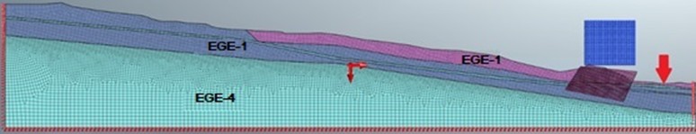
Description of the model based on section 1-1. The overall size of the soil base block is 511×93 m, with a height reduction to 34 m after the landslide mass. The developed model is approximated by flat (2D) nodal finite elements of the 2nd order. The total number of finite elements in the model is 18499, nodes – 18755 (Fig. 1).
Fig. 1Calculated model for section 1-1
The results of modeling the landslide of an inclined massif along sections 1-1 and 3-3, using the Midas GTS NX PC and using the Mohr-Coulomb model for soil determination, are shown in Figs. 2-4.
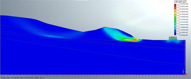
The safety factor of the dry slope of section 1-1 calculated by the SAM method is 2.3 and by the SRM method is 3.1 (Fig. 2).
Fig. 2Calculation of the stability of the dry slope of section 1-1 taking into account the railway embankment
The maximum displacements when calculating the stress-strain state (SDS) of a dry slope, taking into account seismic impact along the axis, reach approximately 46 sm at the top of the landslide site (Fig. 3). In turn, the maximum displacements along the axis reach about 37 sm at the model angle, while 90.3 % of model displacements are about 6 mm.
The safety factor of the dry slope of section 1-1, taking into account seismic impact, calculated using the SAM method, is 1.6 and the SRM method is 1.51.
It should be noted that the dry slope calculation using the SAM method was performed only for the protrusion shaft of an unstable landslide mass, while the SRM method automatically determines the most unstable sections and tensile forces in the mass using the strength reduction method.
Calculations for determining the total stress without seismic impact along the and axes, as well as stability, were performed using the SRM and SAM methods for wet slopes using the calculated model for section 1-1 (Table 1).
Table 1Slope stability coefficients for variants No. 1, No. 2, No. 3, and No. 4. Main combination of loads (excluding seismic impact)
Name of the calculated case | Main combination of loads | ||
SRM method | SAM method | ||
1. | Variant No. 1 (1-1 section, dry slope) | 2.3 | 3.1 |
2. | Variant No. 2 (section 1-1 wet slope) | 2.2 | 1.65 |
3. | Variant No. 3 (3-3 section of dry slope) | 2.8 | 2.33 |
4. | Variant No. 4 (section 3-3 wet slope) | 1.9 | 1.59 |
5. | Variant No. 1 + railway embankment (1-1 section, dry slope) | 2.28 | 3.0 |
6. | Variant No. 2 + railway embankment (section 1-1 wet slope) | 2.01 | 1.65 |
7. | Variant No. 3 + railway embankment (3-3 section of dry slope) | 2.8 | 2.33 |
8. | Variant No. 4 + railway embankment (3-3 section wet slope) | 1.9 | 1.59 |
The reserve coefficient calculated using the SAM method is 1.65 and the SRM method is 2.2.
Similar calculations for determining the total stress along the and axes, slope stability, as well as deformations in the plane stress state along the and axes were performed using the SRM and SAM methods for wet slopes using the calculated model for section 1-1 taking into account seismic impact.
Fig. 3X-axis displacement isoplates when calculating the stress-strain state (SDS) of a wet slope, taking into account seismic impact
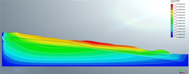
Fig. 4Displacement isotopes along the Y axis when calculating the stress-strain state (SDS) of a dry slope, taking into account seismic impact
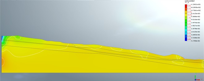
The maximum displacements of the dry slope, taking into account seismic impact, reach approximately 41 sm at the model angle, while 97.1 % of model displacements are between 0.8 and 5.3 sm, marked in blue in Fig. 4.
Analysis of the calculation results allowed us to establish that the reserve coefficient calculated using the SAM method is 1.12 and the SRM method is 1.27.
Based on the results of performing the calculated justification, the results of the stability of the slopes of the landslide massif and the stress-strain state were obtained for four variants, taking into account seismic impact and railway embankment (Table 2).
Table 2Slope stability coefficients for variants No. 1, No. 2, No. 3, and No. 4. (Special combination of loads taking into account seismic impact)
Name of the calculated case | Main combination of loads | ||
SRM method | SAM method | ||
1. | Variant No. 1 (1-1 section, dry slope) | 1.51 | 1.6 |
2. | Variant No. 2 (section 1-1 wet slope) | 1.27 | 1.12 |
3. | Variant No. 3 (3-3 section of dry slope) | 1.47 | 1.66 |
4. | Variant No. 4 (section 3-3 wet slope) | 1.21 | 1.16 |
5. | Variant No. 1 + railway embankment (1-1 section, dry slope) | 1.51 | 1.6 |
6. | Variant No. 2 + railway embankment (section 1-1 wet slope) | 1.27 | 1.11 |
7. | Variant No. 3 + railway embankment (3-3 section of dry slope) | 1.46 | 1.65 |
8. | Variant No. 4 + railway embankment (3-3 section wet slope) | 1.20 | 1.15 |
4. Conclusions
According to the data obtained, it can be concluded that there is a risk of landslides at the 103 km section of the “Chashmaihafizon-Akrabat” section. Despite the fact that the stability reserve coefficients calculated using the SRM method have sufficient indicators, the SAM method shows that the stability reserve of the wet slope under seismic impact is insufficient.
Comparison of the variants, taking into account and without taking into account the influence of the railway embankment and the corresponding load from the composition, shows that the stability reserve coefficient tends to decrease, especially in cases of seismic impact.
However, it should be noted that the assessment of landslide risk was carried out without considering the movement of mudflows along the slope, which will undoubtedly worsen the actual situation of slope stability.
References
-
V. K. Epishin, “Features of the interaction of the geological environment and engineering structures,” in Theoretical foundations of engineering geology. Social and Economic Aspects, 1985.
-
S. I. Matsiy, D. V. Leyer, and E. V. Bezuglova, “Monitoring and modeling of landslide processes using the example of the city of Sochi,” Construction and Architecture, Vol. 1, pp. 54–61, 2013.
-
“Methodological recommendations for risk assessment in the railway infrastructure of JSC RZD,” JSC RZD, Moscow, 2011.
-
S. Djabbarov, R. Mukarramov, A. Zhahongir, and G. Bimurzaev, “Evaluation of landslide risk on railway line Tashguzar-Boysun-Kumkurgan based on results of field monitoring,” in 3rd International Symposium on Civil, Environmental, and Infrastructure Engineering (ISCEIE) 2024, Vol. 3317, p. 060025, Jan. 2025, https://doi.org/10.1063/5.0267395
-
S. T. Djabbarov and R. H. Mukarramov, “Monitoring and forecasting of hazardous geological processes using a 3D scanning system,” in Asia-Pacific Conference on Applied Mathematics and Statistics, Vol. 2471, p. 030014, Jan. 2022, https://doi.org/10.1063/5.0089561
-
S. T. Djabbarov and R. H. Mukarramov, “Influence of engineering and geodynamic processes on stability of transport infrastructure,” in E3S Web of Conferences, Vol. 401, p. 01082, Jul. 2023, https://doi.org/10.1051/e3sconf/202340101082
-
S. S. Salixanov, F. Z. Zokirov, Y. T. Xakimova, and G. B. Ismailova, “The effect of increasing loads on foundations of operating bridges,” in E3S Web of Conferences, Vol. 401, p. 01080, Jul. 2023, https://doi.org/10.1051/e3sconf/202340101080
-
C. Raupov, A. Karimova, F. Zokirov, and Y. Khakimova, “Experimental and theoretical assessment of the long-term strength of lightweight concrete and its components under compression and tension, taking into account the macrostructure of the material,” in E3S Web of Conferences, Vol. 264, p. 02024, Jun. 2021, https://doi.org/10.1051/e3sconf/202126402024
-
R. A. Niyazov, “Opolzni Uzbekistana (development trends at the XXI century)”.
-
S. I. Djabbarov, “Prospects for raising passenger train speed on the reconstructed section of the railway UZBEKISTAN,” Transport Problems, Vol. 11, No. 4, pp. 103–110, 2016.
-
F. M. Miryusupov, S. B. Bozorov, and A. M. Akhunzhanov, “Report on the monitoring service for dangerous geological processes in the mountainous and foothill areas of the south-east of the Kashkadarya region,” Report of the Karshi SS for 2004-2007, 2007.
-
E. K. Utaev, K. H. Davlatov, and U. U. Batirov, “Report on monitoring hazardous geological processes in the mountainous and foothill areas of the southeastern part of the Kashkadarya region,” Karshi Monitoring Station for 2008-2011, 2011.
-
I. A. Komissarov, M. Kalinina, E. A. Egorchenkova, and N. Korotchenko, “Method of calibration of spherical reservoirs by the method of ground laser scanning,” Problems of Collection, Preparation and Transportation of Oil and Oil Products, Vol. 4, No. 102, pp. 163–170, 2015.
-
J. Krahn, Stability Modeling with SLOPE/W. An engineyering methodology. 2004.
-
T. Lambe, Soil Mechanics. New York: John Wiley and Sons, 1969.
-
T. Keyegan, B. Abbott, and D. Cruden, “Railway ground hazard risk scenario,” in Geotechnique and Natural Hazards, 2003.
-
R. Chowdhury, P. Flentje, and G. Bhattacharya, Geotechnical Slope Analysis. UK, London: CRC Press, 2009, https://doi.org/10.1201/9780203864203
-
A. Khakimov, G. Kutumova, and Z. Mirzaeva, “Current trends in the development of automation surveying support in the construction of subways,” in E3S Web of Conferences, Vol. 168, No. 153, May 2020, https://doi.org/10.1051/e3sconf/202016800010
-
C. Raupov and G. Malikov, “Creep in expanded clay concrete at different levels of stress under compression and tension,” in E3S Web of Conferences, Vol. 365, p. 02008, Jan. 2023, https://doi.org/10.1051/e3sconf/202336502008
-
C. Raupov and G. Malikov, “Comparison of microcrack formation boundaries determined by complex of physical methods with long-term strength of expanded clay concrete under different types of stress state,” in E3S Web of Conferences, Vol. 365, p. 02023, Jan. 2023, https://doi.org/10.1051/e3sconf/202336502023
-
S. T. Djabbarov, “The impact on people and facilities of air flow caused by high-speed train traffic,” Procedia Engineering, Vol. 189, pp. 554–559, Jan. 2017, https://doi.org/10.1016/j.proeng.2017.05.088
-
N. Nishonov, D. Bekmirzaev, A. Ergashov, Z. Rakhimjonov, and A. Khurramov, “Underground polymeric l-shaped pipeline vibrations under seismic effect,” in E3S Web of Conferences, Vol. 264, p. 02037, Jun. 2021, https://doi.org/10.1051/e3sconf/202126402037
About this article

The authors have not disclosed any funding.
The datasets generated during and/or analyzed during the current study are available from the corresponding author on reasonable request.
The authors declare that they have no conflict of interest.
