Abstract
This study investigates the deflection of a cantilever plate fixed at one end under the action of soil self-weight and additional surcharge loads. Based on experimental observations and theoretical calculations, an exponential expression is proposed to describe the plate’s deflection profile. Differentiation of this expression yields the corresponding stress distribution, which is compared against the conventional Coulomb-Mohr earth-pressure formulation. The results show that the exponential model provides a more accurate assessment of stresses on slopes and flexible retaining walls, highlighting its practical significance for design and evaluation. The proposed exponential approach can also serve as a foundation for dynamic and seismic extensions in future studies.
Highlights
- An exponential model is proposed to describe plate deflection under soil self-weight and surcharge loads more accurately than classical linear methods.
- Stress distribution derived from the deflection function shows a nonlinear (parabolic) profile, differing from the linear Coulomb–Mohr theory.
- Experimental results demonstrate that the exponential model closely matches measured plate deflections along the entire height.
- The proposed approach improves prediction of earth pressure for slopes and retaining walls under combined loading conditions.
- The model provides a reliable basis for future extension to dynamic and seismic soil–structure interaction analysis.
1. Introduction
In geotechnical engineering, the interaction between soil and structural elements is crucial for stability assessment. Under natural and external loads, earth pressure causes plate bending, deformation, and stresses – observable in slopes, retaining walls, foundations, and laboratory models. Measuring and analyzing these deformations ensures reliable evaluation of the soil-structure system’s stability [1].
Classical models for earth pressure – Coulomb (1776) [2] and Rankine (1857) [3] – remain fundamental but simplify the real soil-structure interaction and often fail to reflect actual stress distributions. In structural mechanics, plate bending is obtained from differential equations with boundary conditions and loads, yet this approach overlooks the nonlinear behavior of soils. Recent studies [13], [14] introduced exponential-type functions for plate deflection, achieving better accuracy in stability analysis. Therefore, analyzing plate deflection under self-weight and surcharge to derive stress distribution is a relevant and practical research focus.
2. Research objective
The main goal of this study is to analyze, both theoretically and experimentally, the deflection of a plate subjected to soil self-weight and additional surcharge loads, to determine the resulting stresses from the deflection function, and to compare them with classical soil-mechanics models. The key tasks include: calculating plate deformation using the classical plate-bending equation, deriving a new exponential analytical expression, differentiating the deflection function to obtain the stress distribution, comparing the results with traditional pressure–depth relationships.
This research aims not only to advance theoretical understanding but also to propose a more reliable practical method for evaluating stress states in soil–structure systems.
2.1. Experiments and analysis
To evaluate slope stability, laboratory model tests were carried out in a soil box with a steel plate fixed at the bottom and free at the top, simulating a retaining wall. The back of the plate was gradually filled with fine sand and crushed stone, where earth pressure was generated by the soil’s unit weight () and an additional surface surcharge (). The steel plate ( 1.25 m, 0.26 m, 5 mm, 2.1×10⁵ MPa) was instrumented with LVDT sensors (accuracy 0.01 mm). All instruments were calibrated, and measurements repeated three times for consistency.
Deflection was analyzed both experimentally and theoretically: lateral displacements were recorded by sensors, and theoretical deflection was computed by modeling the plate as a cantilever beam under triangular loading using classical structural mechanics formulas:
where, denotes the linearly varying (triangular) load acting on the cantilever due to the soil’s self-weight (kPa); is the flexural rigidity of the cantilever (kN·m2); is the cantilever height (m); and is the elevation (or depth) of the point under consideration along the cantilever (m).
When an additional surface surcharge acts on the soil, the plate deflection was evaluated assuming a trapezoidally distributed load, and computed accordingly:
where, denotes the surcharge pressure applied to the soil (kPa), and denotes the combined pressure due to the soil’s self-weight together with the surcharge (kPa).
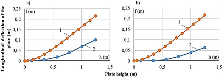
The linearly varying loads (triangular and trapezoidal) acting on the cantilever due to soil self-weight and surcharge were determined, and numerical calculations were carried out to obtain the deflection function. Fig. 1 shows the comparison between the experimental and analytical deflection curves.
From the graph, it is clear that the experimentally measured deflection of the plate is smaller than the theoretical prediction for the cantilever. Considering this, the bending differential equation along the neutral axis was formulated as follows:
Fig. 1Comparison of plate deflections: a) crushed stone; b) sand: 1 – analytical; 2 – experimental
From this, the distributed pressures are where is the lateral earth-pressure coefficient, and is the soil internal friction angle (in degrees).
Brief note on the general solution:
The integration constants in this equation are determined from the boundary conditions for a cantilever beam fixed at one end, evaluated at 0 and respectively.
; , , therefore , . We set 0. Substituting the integration constants into Eq. (2), the deflection function for a trapezoidally distributed load is obtained as follows:
Using Eq. (5), we construct the deflection function of the cantilever beam. To compare the deflection obtained from Eq. (5) with that derived from Eqs. (1) and (2), we plot both curves in Fig. 2.
Fig. 2Longitudinal deflection of the plate: a) according to differential and conventional methods; b) exponential model and experimental results. Curves: (1) – experiment, (2*) – differential, (2) – exponential, (3) – conventional theory
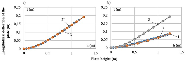
This equation represents the deflection of a cantilever beam (retaining wall) under linearly varying loads (triangular and trapezoidal). Using Eq. (5), we obtain the deflection function of the cantilever beam. As seen from the graph in Fig. 2(a) the deflection function of the cantilever sheet determined via the differential equation coincides with the theoretically obtained result. Taking this into account, we next consider the deflection equation and solution of a cantilever beam under exponentially varying loads. We take the curved distributed load in exponential form and set its area equal to that of the trapezoid:
For the boundary conditions at and : , , where and , is a variable coefficient determined from the integral equality of the triangle and trapezoid areas; taking this into account, we rewrite as follows:
From this equation, we integrate and set it equal to the area of the trapezoid:
From the integral solution Eqs. (6) we determine the unknown parameter . In this equation, H denotes the pressure value at :
We formulate the bending differential equation along the beam’s neutral axis:
We obtain the general solution:
The integration constants in this equation are determined, respectively at and from the boundary conditions for a cantilever beam fixed at one end.
; ; ; accordingly, from Eq. (3):
We take them to be equal. Substituting them into Eq. (2), we obtain the following expression for the deflection function under a trapezoidally distributed load:
Using the stated differential equation, we plot in Fig. 2(b) the deflection curve of a beam with stiffness EI under uniformly distributed loads corresponding to the trapezoidal and exponential profiles.
As seen in Fig. 2(b) the deflection function of the cantilever sheet (plate) constructed using the values obtained experimentally and from the exponential equation are very close to each other. Taking this into account, the previously formulated differential Eq. (10) for the exponential relation was used to determine the soil stress distribution along the plate height, and the results were compared with the conventional Coulomb-Mohr theory. In soil mechanics, we treat the plate as a retaining wall; in this case, the load arising from the soil’s self-weight is triangular, while an additional surcharge on a slope produces a trapezoidal load. At present, this problem is addressed by various methods. Among the conventional approaches, the linear load-distribution methods of Rankine [1] and Coulomb [2] are widely applied. Let us assume that the slope behind the retaining wall is in a state of limit equilibrium. If a uniformly distributed load is applied on the slope surface, then the principal stresses act on a horizontal plane passing through any point located behind the wall:
Let us determine the horizontal pressure exerted by the soil on the wall:
The resultant forces generate the active pressure with respect to the retaining wall:
For Eq. (3) can be written as follows:
In that case, for cohesionless soils – such as sand and crushed stone – where and the relationship between the principal stresses is written as follows:
Based on (4) and (5):
These data make it possible to derive the linear load distributions on the retaining wall produced by the soil’s self-weight and additional loads. According to the linear load-distribution theory, the pressure acting on the retaining wall decreases with height (or increases with depth):
where, is the soil unit weight (kN/m3), is the depth (or height) of the soil behind the retaining wall (m); is the lateral earth-pressure (Rankine) coefficient; and is the maximum stress, which we take as . The given stress formula applies to a linear distribution; multiplying it by the plate width b converts it into a uniformly distributed load over the plate width [1]:
In this formula, is the value of the additional (surcharge) load transmitted to the soil; if no surcharge is present, we set 0.
Using the fourth derivative of the exponential equation and the Coulomb-Mohr relations, the stress values in the soil along the plate height were determined, and based on these values the resultant action diagram (épure) on the plate was constructed. The graph of this stress action diagram is presented in Fig. 3.
Fig. 3Comparison of soil stress diagrams: 1 – Coulomb-Mohr (linear); 2 – exponential model (parabolic)
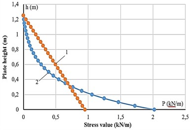
As shown in Fig. 3, the stress epure from the Coulomb-Mohr theory is linear, while that from the fourth derivative of the exponential relation is parabolic. Consequently, the bending moment from a parabolic pressure distribution may be smaller, since its resultant acts lower than /3. This confirms that the exponential model better represents real slope and retaining-wall conditions.
3. Discussion
The proposed exponential model, validated under static laboratory conditions, showed excellent agreement with experimental deflections. However, it does not yet account for dynamic soil behavior. Future work should extend the model to dynamic or seismic loading using numerical methods (e.g., PLAXIS 3D, ABAQUS, MIDAS GTS) and verify its scalability through large-scale field tests.
4. Conclusions
The conducted research shows that the deflection and stress state arising in a plate under soil self-weight and additional surcharges are described more accurately by an exponential model than by traditional theory. Comparing experimental results with theoretical calculations indicates that the stresses obtained via the exponential equation differ from the linear distribution based on the Coulomb-Mohr theory and are closer to real behavior.
These findings open the possibility of using the exponential model to assess the stability of slopes and retaining walls. The approach serves as a reliable tool for analyzing stresses and deformations in structure-soil systems, contributing to improved safety and economic efficiency in practical construction. In particular, for slope reinforcement, retaining-wall design, and foundation calculations, the exponential model may yield more accurate results than conventional methods. Overall, the exponential modeling framework provides a valuable analytical basis for future studies on soil-structure interaction and slope stability under both static and dynamic conditions.
At the same time, this study focused mainly on static conditions. Future work should examine the performance of the exponential model under seismic and dynamic loading, determine parameters for different soil types (sand, gravel, clay, and mixtures), and deepen the analysis through numerical modeling (e.g., PLAXIS, MIDAS, ABAQUS). It is also advisable to conduct large-scale field tests and investigations on full-scale structures.
References
-
A. Z. Khasanov and Z. A. Khasanov, “Stability of natural slopes and determination of the pressure of incoherent soils on fences,” Soil Mechanics and Foundation Engineering, Vol. 61, No. 1, pp. 13–19, Apr. 2024, https://doi.org/10.1007/s11204-024-09937-z
-
C. A. Coulomb, Essay on the Application of the Rules of Maxima and Minima to Certain Problems of Statics Related to Architecture. (in French), 1776.
-
Rankine and W. J. M., “On the stability of loose earth,” Philosophical Transactions of the Royal Society of London, Vol. 147, pp. 9–27, 1857, https://doi.org/10.1098/rstl.1857.0003
-
K. Terzaghi, Theoretical Soil Mechanics. New York, NY: Wiley, 2007, https://doi.org/10.1002/9780470172766
-
J. E. Bowles, “Foundation analysis and design,” in GeoShanghai International Conference 2006, May 2006, https://doi.org/10.1061/9780784408650
-
J. Knappett and R. F. Craig, Craig’s Soil Mechanics. CRC Press, 2019, https://doi.org/10.1201/9781351052740
-
S. Timoshenko and S. Woinowsky-Krieger, Theory of Plates and Shells. New York: McGraw-Hill, 1959.
-
D. Choudhury and S. Nimbalkar, “Seismic passive earth-pressure coefficients using pseudodynamic method,” Journal of Geotechnical and Geoenvironmental Engineering, Vol. 132, No. 12, pp. 1541–1548, 2006.
-
G. Chen, B. Xu, and H. Sun, “Numerical analysis of retaining wall under combined static and dynamic loading,” Computers and Geotechnics, Vol. 112, pp. 220–231, 2019.
-
X. Li and Y. Wang, “Analytical solutions for deflection of retaining walls subjected to soil pressure,” Soil Mechanics and Foundation Engineering, Vol. 57, No. 2, pp. 123–130, 2020.
-
L. Xu and Y. Zhou, “Exponential distribution models for soil pressure on retaining walls,” International Journal of Geomechanics, Vol. 23, No. 4, p. 04023045, 2023.
-
S. Bhattacharya and M. D. Bolton, “Experimental study on soil-structure interaction of retaining elements under lateral loads,” Géotechnique, Vol. 71, No. 3, pp. 210–225, 2021.
-
S. L. Kramer, Geotechnical Earthquake Engineering. London: Pearson Education, 2014.
-
O. C. Zienkiewicz, M. Pastor, and A. H. C. Chan, Computational Geomechanics with Special Reference to Earthquake Engineering. Boca Raton: CRC Press, 2020, https://doi.org/10.1201/9780429343441
-
A. Khosravi and H. Taiebat, “Advanced constitutive models for seismic slope stability assessment,” Soil Dynamics and Earthquake Engineering, Vol. 156, p. 10723, 2022, https://doi.org/10.1016/j.soildyn.2022.107230
-
J. Zhang and H. I. Ling, “Stress-strain response of granular soils under combined loading conditions,” Journal of Geotechnical and Geoenvironmental Engineering, Vol. 147, No. 7, p. 04021056, 2021.
-
A. M. Hassan and H. El Naggar, “Numerical modeling of soil-structure interaction in retaining systems,” Soil Mechanics and Foundation Engineering, Vol. 57, No. 6, pp. 421–430, 2020, https://doi.org/10.1007/s11204-020-09549-5
-
G. Wang and L. Gao, “Application of nonlinear soil models in slope stability analysis,” Engineering Geology, Vol. 288, p. 106145, 2021.
-
H. Zhou and N. Li, “Analytical method for lateral earth pressure on retaining walls considering soil arching effect,” International Journal of Geomechanics, Vol. 22, No. 10, p. 04022156, 2022.
-
S. Bhattacharya, M. D. Bolton, and S. P. G. Madabhushi, “Seismic behaviour of retaining walls: Experimental and numerical insights,” Géotechnique Letters, Vol. 10, No. 2, pp. 205–213, 2020.
-
“ISO 23469:2019 – Bases for design of structures: seismic actions for geotechnical design,” ISO, Geneva, Switzerland, 2019.
-
“KMK 2.01.03-19: Construction considering seismic actions,” (in Uzbek), Ministry of Construction of the Republic of Uzbekistan, Tashkent, Uzbekistan, 2020.
About this article

The authors have not disclosed any funding.
The authors gratefully acknowledge the support of Prof. A.Z. Khasanov for valuable guidance and discussion.
The datasets generated during and/or analyzed during the current study are available from the corresponding author on reasonable request.
The authors declare that they have no conflict of interest.
