
Abstract
Due to factors such as tooth clearance and fretting wear during the transmission process, the vibration generated by splined pairs not only negatively impacts the stability of the entire transmission system, but also affects ride comfort. To reveal the vibration and fretting wear mechanisms of splined pairs in the transmission system of new energy vehicles, firstly, a comprehensive time-varying meshing stiffness model of splined pairs considering the actual number of meshing tooth pairs is established. Combining the pure torsional dynamics model of involute splined pairs with the lumped parameter method, the vibration displacement and velocity of involute splined pairs are investigated, considering the tooth side clearance and load variations. Then, a fretting wear calculation model is constructed based on the FEM model to investigate the influence of fretting wear-induced tooth side clearance increase on the meshing stiffness of splined pairs. Finally, fretting wear is incorporated into the theoretical dynamics model to study its impact on the dynamic characteristics of splined pairs, thereby verifying the accuracy of the theoretical model and conclusions, and providing reliable theoretical support for the optimized design of involute splined pairs.
1. Introduction
As an environmentally friendly and energy-saving means of transportation, new energy vehicles have received increasing attention and promotion [1]. The spline pair is a common mechanical transmission component, consisting of a series of uniformly distributed teeth, typically used to connect shafts and transmit rotational motion and torque between them. During the operation of new energy vehicles, involute spline pairs are frequently employed under complex working conditions, particularly during acceleration, driving, and braking phases. These processes subject the internal and external splines to periodic fluctuating loads, resulting in alternating contact stresses on the tooth surfaces and minor vibrations between the teeth. Such minor vibrations and alternating stresses can easily lead to fretting wear and tooth fracture, significantly compromising the reliability and lifespan of the splines. Consequently, this affects the overall performance and safety of the entire transmission system.
In depth research on spline vibration and micro motion wear of new energy vehicle transmission systems has practical significance for improving the performance, stability, and ensuring driving safety of traditional systems. Firstly, the optimization design of the transmission system of new energy vehicles can reduce or eliminate vibration phenomena, thereby improving the quality and driving safety of new energy vehicles. Secondly, this can extend the service life of various components in the transmission system and reduce maintenance costs. In summary, in-depth research on the vibration and micro wear of splines in the transmission system of new energy vehicles has important theoretical value and engineering significance, and can contribute to the further development of the new energy vehicle industry.
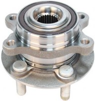
1.1. Research status on dynamic characteristics of spline
S Monti et al. evaluated the spline wear phenomenon by numerically simulating the entire crane transmission system and comparing the actual material properties with those in the literature [2]. The use of spline connections in industrial applications often results in excessive tooth side pressure, which often leads to oversized splines and, in some cases, hub connection failure. U. Burgdorf et al. introduced a new spline calculation standard to address this issue through their paper [3]. Mura et al. studied the position of the resultant force generated by contact pressure distribution in involute spline teeth under ideal and misalignment conditions using finite element method. The results indicate that the difference between the diameter of the resultant force and the diameter of the pitch circle is not very significant in the ideal and misaligned states [4]. A Khalik et al. used finite element software to study the contact and bending stress of spline shaft teeth by changing the most effective design parameters of internal and external splines (pressure angle, number of teeth, fillet radius, and normal modulus). The results show that increasing the pressure angle and fillet radius will reduce the bending stress between the inner and outer spline teeth, increase the contact stress, while increasing the normal modulus and number of teeth will reduce the contact stress and bending stress [5]. OI Smetannikov et al. provided mathematical expressions for the interaction between two elastic bodies in the solution of contact interaction problems in involute spline connections, and studied the convergence of numerical solutions [6]. Using ANSYS software, Dong [7] analyzed the force conditions of the steering torsion bar during the cold rolling forming process. Niu [8] established a spline pair model using piecewise linear function method, and based on this, developed dynamic equations considering double steel plates and friction plate flower key pairs. Huang Renzhong et al. used finite element software to reveal the temporal evolution of contact stress and relative displacement [9]. Walton [10] studied the effects of external forces and frequency on diagonal stiffness and damping coefficients, and explored the mechanism and root cause of internal friction instability in rotors caused by axial spline couplings. Choi [11] conducted experimental research on the influence of spline tolerance on the dynamic characteristics and noise of the system. Kahraman [12] constructed a segmented linear dynamic model for analyzing spline connections that are simultaneously affected by tooth flank clearance and circumferential tooth position errors. Zhang [13] established an improved dynamic model for spline couplings, which introduces static misalignment caused by installation and manufacturing errors and dynamic misalignment caused by dynamic vibration displacement between internal and external splines. By using the potential energy method to calculate the meshing stiffness, the equivalent stiffness and excitation force were determined, and their accuracy was verified using software. The results indicate that static misalignment leads to severe uneven load distribution, while dynamic misalignment has a relatively small impact and can be ignored [14].
1.2. Research status on micro motion wear of spline pair
Leen [15] used finite element method to study the effect of micro motion wear on micro motion fatigue parameters of spline couplings. Research has found that partial sliding wear caused by high frequency, rotational torque, and fluctuating torque may increase the micro fatigue parameters far from the contact edge, leading to reduced lifespan. Qureshi [16] used a dedicated test bench to test the crown tooth spline coupling of nitrogen hardened 42CrMo4 material, focusing on analyzing the micro motion wear and clearance changes under different torques and misalignment angles. Madge [17] quantitatively evaluated the effect of wear on micro motion fatigue behavior by calculating local contact pressure and wear under sliding, combined with fatigue damage parameters based on shear strain (critical plane fatigue social parameters). Cuffaro [18] investigated the micro motion wear phenomenon of the tooth surface of a spline coupling under misaligned conditions, aiming to identify its damage through surface roughness. Ki [19] used the modified Archard equation combined with experimentally obtained wear coefficient, contact pressure, and stroke to calculate the wear depth. Cur à [20] used the first Ruiz parameter as an indicator to quantify wear damage, and conducted experimental tests using a dedicated testing device to verify the theoretical prediction results based on the ISO Ruiz diagram. McColl [21] presented a novel simulation method to the public in their paper, which studied the evolution of micro motion wear and micro motion variables with wear cycles in cylindrical planar micro motion structures. This method combined the modified Archard wear equation and was applied to commercial finite element software. Jiang [22] proposed a method for predicting micro motion wear in complex couplings and validated it through a scaled down model of aviation engine type spline couplings. By a finite element dynamic model, C Zhang [23] conducted on the issue of incorrect installation affecting safe operation in the spline connection-flexible coupling-rotor system in aviation and marine industries. By using the potential energy method, Zhang [24] calculated the meshing stiffness, the equivalent stiffness and excitation force. Considering the double steel plates and friction plate spline pairs, to investigate the vibration characteristics of wet clutches and the dynamic load characteristics of spline pairs. By using a piecewise linear function method, Niu [25] established a spline pair model and formulated a dynamic equation that takes into account the double steel plate and friction plate spline pair.
Through the above research literature, it can be found that the dynamic performance and micro motion wear of spline pairs have received extensive research attention from scholars at home and abroad. Although scholars have conducted relevant research on the micro motion wear and dynamic model establishment of spline pairs, there is still insufficient research on the vibration and micro motion wear of splines in the transmission system of new energy vehicles. This article takes the involute spline pair of the transmission system of new energy vehicles as the research object, and deeply analyzes the micro vibration and micro wear phenomena of the transmission system through the comprehensive application of theoretical modeling and numerical calculation methods. Firstly, the centralized parameter method is used to establish the dynamic model and nonlinear differential equation system of the involute spline pair in a new energy vehicle transmission system. By combining Maple software with numerical analysis, the micro vibration and micro wear phenomena of the transmission system are analyzed, revealing the influence of micro wear of the involute spline pair on micro vibration. A simulation model is established using Adams simulation software to verify the results of numerical analysis.
2. Dynamic model of spline meshing pair considering actual number of meshing teeth
In order to more accurately describe the dynamic characteristics of the involute spline pair during the transmission process, the segmented method was used to conduct in-depth analysis and calculation of the single tooth meshing stiffness of the involute spline pair. In depth analysis of the influence of tooth flank clearance on the meshing performance of involute spline pairs, and the concept of actual meshing tooth pairs is introduced. By combining this concept with single tooth meshing stiffness, the comprehensive time-varying meshing stiffness of involute spline pairs was further analyzed, and the inherent mechanism and variation law of time-varying were revealed. The aim is to lay a solid theoretical foundation for the subsequent solution of dynamic equation systems and in-depth exploration of the motion characteristics of new energy vehicle transmission systems.
2.1. Calculation of single tooth mesh stiffness of involute spline pair
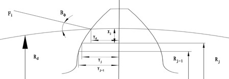
Consider each involute spline pair’s spline teeth as a composite structure composed of equally thick segments, some model simplifications and assumptions are made, as shown in Fig. 2.
In Fig. 2, is the contact angle; is any load acting on the position of the dividing circle on the tooth profile; is the half tooth width at the position of the dividing circle, measured in millimeters; is the distance from the position of the dividing circle to the upper surface of each tooth segment, measured in millimeters; is the half tooth width of the th segment, measured in millimeters; is the radius size corresponding to the half tooth width of the th segment, measured in millimeters. Divide the spline teeth into multiple small segments for consideration, and the bending deformation of each segment on a single tooth is:
where, is the section moment of inertia of the -th tooth segment, with units in mm4; is the elastic modulus considering the Poisson effect; is the elastic modulus of the spline tooth material, with units in GPa; is the bending deformation at any point g within the -th segment, with units in mm. is the height difference between the -th tooth segment and the -th tooth segment, i.e., the difference between and , with units in mm.The total bending deformation and the single tooth bending flexibility are as below:
The shear deformation of each segment on a single tooth can be obtained from the card theorem as follows:
where is the shear modulus of the -th tooth material of the spline, measured in MPa; is the average surface area of the upper and lower surfaces of the -th tooth, measured in mm2; is the shear deformation at any point g within the th segment, measured in millimeters. The single tooth shear compliance is:
The flexibility of a pair of involute spline teeth is:
The single tooth meshing stiffness :
The half tooth width of the outer and inner splines in section is:
where, is the modulus of the involute spline pair; and are the pressure angles of the outer and inner spline teeth in the th segment, while and are the radius sizes corresponding to the half tooth width of the outer and inner spline teeth in the th segment. The average surface area of the upper and lower surfaces of the -th spline tooth and the sectional moment of inertia of the -th gear segment are as below:
where is the contact length of the spline teeth, measured in millimeters; and are the half tooth widths of the upper and lower surfaces of the -th spline tooth, measured in millimeters. The key pair material studied in this work is 65 Mn, with a shear modulus of 78.5 GPa; Elastic modulus 210 GPa; Poisson’s ratio 0.269. The parameters and results are shown in Table 1 and Table 2.
Number of teeth | Pressure angle | Contact length | Tooth thickness at the top | Pitch diameter | Module | Tooth height |
|---|---|---|---|---|---|---|
36 | 45° | 37.5 mm | 0.65 mm | 36 mm | 1 | 1.8 mm |
Name | Value (m/N) | Name | Value (m/N) |
|---|---|---|---|
Single tooth bending flexibility of external spline | 3.357940×10⁻⁸ | Single tooth shear flexibility of external spline | 4.468781×10⁻⁸ |
Single tooth bending flexibility of internal spline | 2.975050×10⁻⁸ | Single tooth shear flexibility of internal spline | 4.283638×10⁻⁸ |
Single tooth flexibility | 1.508541×10⁻⁷ | Single tooth mesh stiffness | 0.6629×10⁷(N/m) |
2.2. Calculation of mesh stiffness of spline pairs with tooth flank clearance
In practical applications of key pairs, a certain gap is often reserved on the tooth side of the spline pair to provide space for storing lubricating oil, reduce tooth side friction, and avoid tooth surface wear caused by lubricant film rupture. The clearance between involute spline pairs can be divided into radial clearance and circumferential clearance. This article only considers circumferential clearance. Assuming that the clearances on both sides of each tooth of the spline pair are and respectively, without considering the problem of misalignment of the spline shaft, then:
According to the national standard GB/T 3478.1-2008, if the tooth groove width on the internal spline indexing circle is and the tooth thickness on the external spline indexing circle is , then:
When the tooth flank clearance is zero, there are:
In practical engineering, when the tolerance level is 5 and the tooth flank clearance is considered, according to the national standard GB/T 3478.1-2008:
where is the maximum actual tooth slot width of the internal spline, in millimeters; is the maximum actual tooth thickness of the external spline, in millimeters; is the minimum actual tooth slot width of the internal spline, in millimeters; is the minimum actual tooth thickness of the external spline, in millimeters; is the upper deviation of the effective tooth thickness of the external spline, 0; is the total tolerance. Where:
where, is the machining tolerance, μm; is the comprehensive tolerance, μm; is the cumulative tolerance of tooth pitch, μm; is the tooth profile error, μm; is the tooth profile tolerance, μm; is the tolerance factor; is the modulus, mm; is the contact length, mm; is the diameter of the dividing circle, mm. The width of the internal spline groove and the thickness of the external spline teeth both follow a normal distribution [26], and:
where varies with changes in accuracy requirements. The groove width of the internal spline and the tooth thickness on the indexing circle of the external spline approximately follow:
Therefore, and satisfies the following normal distribution:
Randomly select a set of values (1, 2, 3,..., ) that follow a standard normal distribution, then:
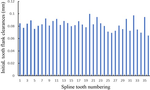
By using the above formula, the initial tooth flank clearance size and distribution of the involute spline pair can be calculated as shown in Fig. 3. Specify 84.7897 μm in the diagram as the tooth flank clearance of the first pair of involute spline teeth, and then number the remaining tooth flank clearances in order. In Fig. 3, it can be seen that the largest backlash among the 36 teeth is the backlash of the 20th pair of teeth, with a size of 99.8530 μm; The smallest tooth flank clearance is the tooth flank clearance of the 36th pair of teeth, with a size of 64.8581μm.
2.3. The comprehensive meshing stiffness considering actual meshing tooth pairs
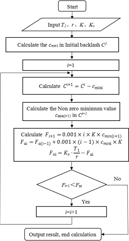
In practical applications of spline pairs, torque is mainly borne by a small portion of spline teeth. This incomplete meshing phenomenon has an undeniable impact on the comprehensive meshing stiffness of involute spline pairs. Therefore, it is particularly important to conduct in-depth research and analysis on the number of meshing teeth of involute spline pairs under actual working conditions. The calculation process for the actual number of meshing teeth of the involute spline pair studied in this chapter is shown in Fig. 4. The total force on the involute spline pair is:
where, is the dynamic load coefficient; is the system input torque; is the radius of the spline indexing circle; The initial clearance is . First, rotate the spline to make contact between the inner and outer splines, eliminating the minimum tooth side clearance in the initial clearance , and obtaining the second set of clearances :
Then, in , find the non-zero minimum tooth flank clearance, , which is the second smallest tooth flank clearance in the initial clearance . The force required to eliminate tooth flank clearance is:
Before eliminating the tooth side clearance , the force required to eliminate its tooth side clearance has already been allocated to the involute spline pair, so the unallocated load is:
If , then can be eliminated. Next, calculate the third set of gaps after eliminating the minimum gap and the second smallest gap :
The force required to eliminate the third small tooth flank clearance is:
The force that has been allocated before eliminating the gap is:
Continuously iterating, when , 2... , the -th group of gaps after eliminating the minimum gap , the second smallest gap ... . When , the actual number of meshing teeth of the involute spline pair under the input torque of the transmission system can be obtained:
In the above equation, is the average actual number of meshing teeth, ; is the amplitude fluctuation coefficient of the external excitation torque; is the angular velocity of the system. Due to the fluctuation of the torque transmitted by the system, the actual number of meshing teeth has time-varying characteristics, is the comprehensive meshing stiffness of the involute spline pair.
2.4. Dynamic models
Due to the clearance increased by tooth contact wear, the meshing vibration in the torsional direction is increased. Therefore, this work only considers vibration in the torsional direction. Under the premise of considering damping in the system, this work uses Lagrange equation to construct the dynamic differential equation system of the system shown in Fig. 5:
Name | Symbol | unit |
|---|---|---|
moment of inertia | , 1, 2, 3, 4 | kg·mm2 |
Rotation angle | rad | |
The pitch radius of the external and internal splines | , | mm |
Torsional damping of the shaft | , | N·mm·s/rad |
Mesh damping of external and internal splines | N·s/mm | |
Torsional stiffness of the shaft | , | N·mm/rad |
Comprehensive time-varying mesh stiffness | N/mm | |
Input torque, load torque | , | N·mm |
Mean excitation torque outside the system | N·mm | |
The fluctuation coefficient of external excitation torque amplitude in the system | none | |
Angular velocity of the system | rad/s | |
Corresponding clearance between spline teeth | , | mm |
The average number of actual meshing spline teeth | none | |
Minimum clearance between spline teeth | mm |
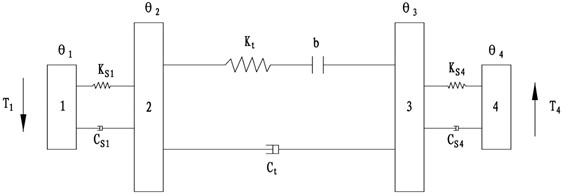
The in Eq. (48) is the segmented linear displacement function of the spline spacing. Its expression is:
2.5. The influence of backlash on the periodic motion characteristics of spline pairs
In the service process of involute spline pairs in new energy vehicle transmission systems, the key parameter of tooth flank clearance has a significant impact on the motion characteristics of the transmission system. Set the input torque , set the meshing damping ratio of the involute spline pair in the new energy vehicle transmission system to 0.03, the torsional damping ratio to 0.01, and the fluctuation coefficient to 0.1 [26]. According to the commonly used experimental conditions of the company, as shown in Fig. 3.1, the average excitation torque outside the system is set to 2000 N·m, and the angular velocity is 3. Using Maple software, the bifurcation diagram of the relative displacement of the involute spline pair with respect to the multiple of the initial tooth flank clearance in the interval [1.0, 1.17] is calculated and shown in Fig. 6.
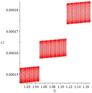
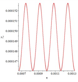
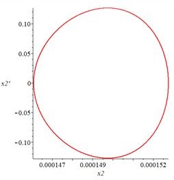
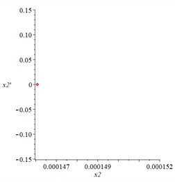
Through in-depth exploration and analysis of the bifurcation diagram, it can be found that as the backlash between the teeth increases, the relative displacement of the involute spline pair shows an overall increasing trend. This trend is directly related to the increase in vibration displacement of involute spline pairs, indicating that the stability of the transmission system is gradually decreasing. Within a specific interval, namely between intervals [1.048, 1.052] and intervals [1.11, 1.2], there is a node where the relative displacement of the involute spline pair increases significantly. When the initial tooth flank clearance multiple is equal to 1, the system response of the transmission system is shown in Fig. 7.
a) Time history diagram
b) Phase trajectory diagram
c) Poincaré section diagram
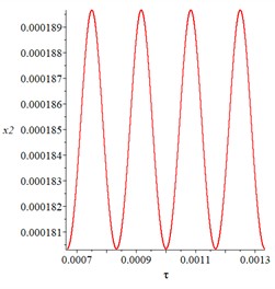
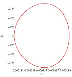
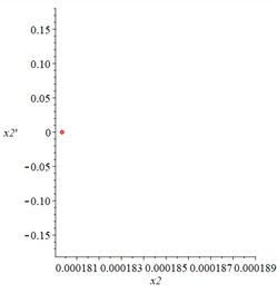
When the value of multiplier is 1.5, compared to when the value of multiplier is 1, the relative displacement of the involute spline pair increases by nearly 40 μm, and the fluctuation value also increases by 3μm (i.e. the vibration displacement increases by 3 μm). In addition, the maximum relative displacement velocity of the involute spline pair increases from 0.125 m/s to 0.18m/s, and the fluctuation value also increases from the original 0.25 m/s to 0.36 m/s.
By comparing Fig. 7 and Fig. 8, it can be seen that as the backlash of the involute spline pair increases, the vibration displacement and vibration velocity of the transmission system will also increase accordingly. Therefore, it can be concluded that an increase in tooth flank clearance will exacerbate the vibration and wear of the transmission system, reduce the stability of the transmission system, and thus affect the quality and driving safety of new energy vehicles.
a) Time history diagram
b) Phase trajectory diagram
c) Poincaré section diagram
3. Prediction of micro motion wear of spline Pair based on finite element method
3.1. The influence of micro motion wear on tooth flank clearance and meshing stiffness
Based on the macroscopic Archard equation, Al-Samarai [27]have derived the corresponding microscopic Archard calculation model:
where, is the wear depth (mm), is the relative slip displacement (mm), is the normal load (MPa), and is load step count. , , are the adhesive wear coefficient, abrasive wear coefficient, and oxidative wear coefficient respectively. Due to limited experimental conditions, the values of , , and in this section are based on the experimental data obtained by Xue [28]. Xue [28] revealed through experiments the time proportions of the main wear types during a fretting cycle of the spline pair: oxidative wear accounts for approximately 30 % of the time, abrasive wear for about 50 %, and adhesive wear for around 20 %. Therefore, the calculation formula for the total wear depth of a single tooth of the spline is:
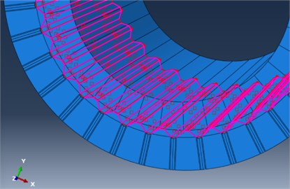
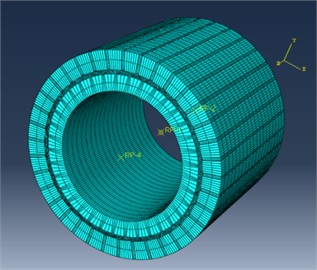
Firstly, use SolidWorks software for 3D modeling and assembly, and save it in format. Open it in ABAQUS software and define the material’s elastic modulus as 210 GPa, Poisson’s ratio as 0.269, and density as 7810 kg/m3. Define the contact in the Interaction module of ABAQUS. When defining contact, all possible contact surfaces of the involute spline pair are defined as a contact pair, as shown in Fig. 9. In the Mesh module, mesh division is performed. To reduce time costs and make reasonable use of global and local seeding, small meshes are set in contact areas that require precise calculations, and large meshes are set in non-contact areas. In the end, the number of grids for external splines was 22572, and the number of grids for internal splines was 38304. Compared to other types of grids, hexahedral grids have significant advantages in accuracy, and the mesh division is shown in Fig. 10.
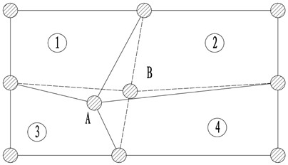
In order to ensure that the node position does not undergo malignant deformation in the wear simulation of involute spline pairs and obtain high-precision simulation results, this chapter uses the ALE adaptive mesh algorithm that comes with ABAQUS software. This algorithm is used to reset the worn surface nodes to ensure mesh quality. The schematic diagram of node reset is shown in Fig. 11. Four units are arranged around node A. By accurately adjusting the position of node A to point B, the grid quality optimization after node coordinate update is achieved.
Next, the Fortran programming language is used to calculate and determine the contact stress, sliding displacement, and micro motion wear of each node along the spline axis after resetting. This process is iterative, adjusting the position of the previous cycle node based on the amount of micro motion wear in the previous cycle. After resetting the node, analyze again and recalculate the contact stress and sliding displacement. This process will be repeated continuously until after times of spline tooth shaping, the micro motion wear amount on each node of the spline is obtained:
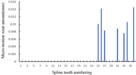
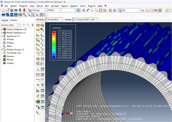
where, is the number of wear cycles, and through ABAQUS finite element simulation, the estimated value of micro motion wear can be obtained when is equal to 0.5×10⁶, as shown in Fig. 12. Fig. 13 shows the simulated stress cloud map.
Input the worn involute spline teeth clearance into the Eq. (38-46), and recalculate the actual number of meshing teeth of the involute spline. The actual number of meshing teeth has increased from 7 pairs to 9 pairs, and the average meshing stiffness has also increased from 4.64×10⁷ N/m to 5.97×10⁷ N/m.
3.2. The influence of micro motion wear on the dynamic characteristics of splines
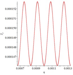
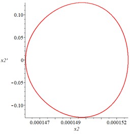
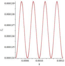
The average excitation torque outside the system is set to 2000 N·m, and the angular velocity ω is set to 3. The time history and phase trajectory diagrams of involute spline pairs that have not undergone micro motion wear, have undergone short-term micro motion wear (with a wear cycle of 0.5×10⁶), and have undergone long-term micro motion wear (with a wear cycle of 5×10⁶) are obtained by solving, as follows.
a) Time history diagram
b) Phase trajectory diagram
a) Time history diagram
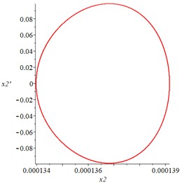
b) Phase trajectory diagram
In the Fig. 16, is the dimensionless time; The relative displacement of the involute spline pair, measured in meters; is the relative displacement velocity of the involute spline pair, measured in meters per second. By comparing Fig. 14 and Fig. 15, it can be seen that due to various factors such as manufacturing process, machining accuracy, and assembly process, the tooth side clearance between the involute spline pairs that have not undergone micro motion wear leads to incomplete meshing of the spline teeth. The actual number of meshing teeth of the spline pair is relatively small, resulting in a lower comprehensive meshing stiffness of the involute spline pair. Therefore, its vibration displacement and vibration velocity are higher than those of the involute spline pair that has undergone short-term micro motion wear.
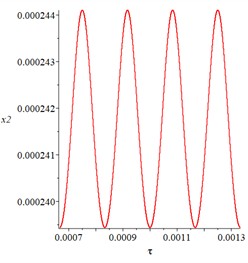
a) Time history diagram
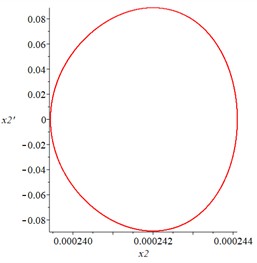
b) Phase trajectory diagram
By comparing Fig. 14 and Fig. 15, it can be seen that after a long period of micro motion wear, the backlash between the teeth of the involute spline pair expands significantly, which leads to an increase in the vibration displacement of the involute spline pair after a long period of micro motion wear. It is worth noting that there is not much change in the vibration speed. This is because after a short period of micro motion wear, the backlash between the teeth of the spline pair tends to be the same, the actual number of meshing teeth of the spline pair increases, and its comprehensive meshing stiffness reaches a high value.
4. Conclusions
This work aims to explore in depth the nonlinear dynamic behavior of involute spline pairs considering micro motion wear. Through the comprehensive application of theoretical analysis and numerical calculation methods, the time history curve graph, phase trajectory graph, and Poincaré section graph are comprehensively used to reveal the dynamic characteristics of spline meshing pairs under complex working conditions, and a series of important conclusions are drawn:
1) As the backlash between the involute spline pairs gradually increases, the relative displacement of the involute spline pairs shows an overall upward trend. This upward trend is directly related to the increase in vibration displacement and vibration velocity of the involute spline pair, and the increase in backlash between the involute spline pair teeth will lead to a decrease in the stability of the transmission system.
2) The effect of backlash on the relative displacement of involute spline pairs is not entirely linear. When the backlash of involute spline pairs increases to a certain node, the relative displacement of involute spline pairs will increase significantly, and the stability of the transmission system will also decrease significantly.
3) In the initial stage of micro motion wear of involute spline pairs, micro motion wear will eliminate the inconsistency of the tooth side clearance of the spline pair, thereby increasing the actual number of meshing teeth of the involute spline pair and increasing the comprehensive meshing stiffness of the involute spline pair.
4) In the initial stage of micro motion wear of involute spline pairs, micro motion wear will reduce the vibration displacement and velocity of involute spline pairs, making the transmission system more stable.
5) After a long period of micro motion wear, the backlash and vibration displacement of the involute spline pair increase. However, due to the increase in the actual number of meshing teeth, it has a large comprehensive meshing stiffness, and its vibration velocity will still be at a relatively low value.
The current study is limited to a suitable robot platform, and does not include physical experiments due to the lack of a high-precision testbed at this stage. To address this limitation, we have established a concrete plan for experimental validation in our ongoing work:
Setup: We will use Splined Micro-Motion Wear Test Machine, which is currently being plan configuration. Conditions: Experiments will cover 0-100 N load, 20-80 °C, with at least 100 repeated trials per condition. Metrics: We will measure [rapid condition 300-1500 r/min. Torque accuracy ±1 %. Timeline: the experiments are expected to be completed within 3 months after this paper’s publication, with results to be reported in a follow-up publication. We believe this planned validation will directly address the reviewer’s concern and further strengthen the evidence for our approach.
References
-
S. Wang, L. Kuai, and L. J. Zhao, “The impact of incentive policies on the promotion and application of new energy vehicles in China,” Technical Economy Ji, Vol. 43, No. 4, pp. 64–74, 2024.
-
S. Monti and M. Guagliano, “Failure analysis of an involute spline coupling of an overhead bridge crane,” Engineering Failure Analysis, Vol. 104, pp. 321–330, Jun. 2019, https://doi.org/10.1016/j.engfailanal.2019.06.010
-
U. Burgtorf, P. Dietz, and M. Garzke, “Calculation of involute splines under elastic material behaviour,” in International Design Conference, 1998.
-
F. Curà and A. Mura, “Analysis of a load application point in spline coupling teeth,” Journal of Zhejiang University SCIENCE A, Vol. 15, No. 4, pp. 302–308, Apr. 2014, https://doi.org/10.1631/jzus.a1300323
-
M. H. F. A. Z. Amjed and A. Khalik, “Experimental and numerical stress analysis of involute splined shaft,” Journal of Engineering, Vol. 18, No. 4, 2012.
-
O. I. Smetannikov and L. R. Shaiakhmetova, “Numerical solution problem of the contact interaction in the involute splined connection,” Applied Mathematics and Control Sciences, No. 1, pp. 55–63, 2014.
-
X. Dong, H. Wang, and X. Zhang, “Analysis of the cold rolling forming process of torsion bar spline based on finite element method,” (in Chinese), Modern Manufacturing Technology and Equipment, Vol. 60, No. 9, pp. 111–113, 2024.
-
Y. Niu, H. Bao, W. Huang, W. Tan, and R. Zhu, “Dynamics modeling and simulation analysis of wet clutch considering spline pair,” Industrial Lubrication and Tribology, Vol. 75, No. 8, pp. 866–874, Oct. 2023, https://doi.org/10.1108/ilt-03-2023-0078
-
R. Huang and T. Zhang, “Dynamic analysis of transmission wear in spline transmission system,” in 21st Annu. Conf. Beijing Mechanics Society and 22nd Annu. Conf, pp. 247–248, 2015.
-
J. F. J. Walton, C.-P. R. Ku, and J. W. Lund, “An experimental investigation of the dynamic characteristics of an axial spline coupling in high-speed rotating machinery,” in 14th Biennial Conference on Mechanical Vibration and Noise: Vibration of Rotating Systems, Vol. 6395, pp. 265–270, 1993, https://doi.org/10.1115/detc1993-0201
-
C. Choi, H. Ahn, Y.-J. Park, S.-C. Kim, and J. Yu, “Dynamic behavior of an agricultural power take-off driveline for rattle noise reduction: Part 1. Effect of spline tolerance on the power take-off rattle noise,” Journal of Terramechanics, Vol. 98, pp. 7–14, Jul. 2021, https://doi.org/10.1016/j.jterra.2021.06.005
-
A. Kahraman, “A spline joint formulation for drive train torsional dynamic models,” Journal of Sound and Vibration, Vol. 241, No. 2, pp. 328–336, Sep. 2002, https://doi.org/10.1006/jsvi.2000.3246
-
C. Zhang, P. Cao, R. Zhu, W. Chen, and D. Wang, “Dynamic modeling and analysis of the spline joint-flexible coupling-rotor system with misalignment,” Journal of Sound and Vibration, Vol. 554, p. 117696, Mar. 2023, https://doi.org/10.1016/j.jsv.2023.117696
-
C. Zhang, R. Zhu, W. Chen, D. Wang, X. Yin, and D. Song, “An improved dynamic model of the spline coupling with misalignment and its load distribution analysis,” International Journal of Mechanics and Materials in Design, Vol. 20, No. 2, pp. 393–408, Sep. 2023, https://doi.org/10.1007/s10999-023-09681-6
-
J. Ding, S. B. Leen, E. J. Williams, and P. H. Shipway, “Finite element simulation of fretting wear-fatigue interaction in spline couplings,” Tribology – Materials, Surfaces and Interfaces, Vol. 2, No. 1, pp. 10–24, 2013, https://doi.org/10.1179/175158308x320791
-
W. Qureshi, F. Cura, and A. Mura, “Experimental characterization of roughness parameters for fretting wear in spline couplings,” Meccanica, Vol. 52, No. 8, pp. 1975–1984, Oct. 2016, https://doi.org/10.1007/s11012-016-0535-7
-
J. Ding, J. Madge, S. B. Leen, and E. J. Williams, “Towards the modelling of fretting wear and fatigue interaction in spline couplings,” Applied Mechanics and Materials, Vol. 5-6, pp. 165–172, Oct. 2006, https://doi.org/10.4028/www.scientific.net/amm.5-6.165
-
V. Cuffaro, F. Curà, and A. Mura, “Surface characterization of spline coupling teeth subjected to fretting wear,” Procedia Engineering, Vol. 74, pp. 135–142, Jun. 2014, https://doi.org/10.1016/j.proeng.2014.06.237
-
E.-J. Kim, S.-D. Lee, and Y.-J. Cho, “A Study on Estimating of Fretting Wear of a Spline Coupling,” (in Korean), Tribology and Lubricants, Vol. 25, No. 4, pp. 256–260, 2009, https://doi.org/10.9725/kstle.2009.25.4.256
-
F. Curà and A. Mura, “Evaluation of the fretting wear damage on crowned splined couplings,” Procedia Structural Integrity, Vol. 5, pp. 1393–1400, Sep. 2017, https://doi.org/10.1016/j.prostr.2017.07.203
-
I. R. Mccoll, J. Ding, and S. B. Leen, “Finite element simulation and experimental validation of fretting wear,” Wear, Vol. 256, No. 11-12, pp. 1114–1127, Nov. 2003, https://doi.org/10.1016/j.wear.2003.07.001
-
Y. Jiang et al., “A modified dynamic model of rotor systems with spline coupling considering misalignment,” Engineering Failure Analysis, Vol. 170, p. 109251, Dec. 2024, https://doi.org/10.1016/j.engfailanal.2024.109251
-
H. Zhu, W. Chen, R. Zhu, J. Gao, and M. Liao, “Modelling and dynamic analysis of spline-connected multi-span rotor system,” Meccanica, Vol. 55, No. 6, pp. 1413–1433, Apr. 2020, https://doi.org/10.1007/s11012-020-01163-9
-
H. Zhang, H. Shang, and C. Yang, “Influence of floating support on the dynamic characteristics of compound planetary gear set,” Journal of Vibroengineering, Vol. 24, No. 2, pp. 272–289, Mar. 2022, https://doi.org/10.21595/jve.2021.22206
-
C. H. H. Ratsimba, I. R. McColl, E. J. Williams, S. B. Leen, and H. P. Soh, “Measurement, analysis and prediction of fretting wear damage in a representative aeroengine spline coupling,” Wear, Vol. 257, No. 11, pp. 1193–1206, Oct. 2004, https://doi.org/10.1016/j.wear.2004.08.003
-
G. Zhang et al., “Important contributions of metal interfaces on their tribological performances: from influencing factors to wear mechanisms,” Composite Structures, Vol. 337, p. 118027, Mar. 2024, https://doi.org/10.1016/j.compstruct.2024.118027
-
R. A. Al-Samarai and Y. Al-Douri, Materials Horizons: from Nature to Nanomaterials. Singapore: Springer Nature Singapore, 2024, https://doi.org/10.1007/978-981-97-1168-0
-
X. Xue, Y. Li, K. Lin, L. Sui, Y. Jiang, and N. Zhang, “A study on the influence of nonlinear vibration on fretting damage of involute spline pairs in aero-engines,” Lubricants, Vol. 11, No. 12, p. 515, Dec. 2023, https://doi.org/10.3390/lubricants11120515
About this article

The author would like to express gratitude to the 2026 Hubei Provincial Science and Technology Plan Project: the 2026 Science and Technology Talent Service Enterprise Project, “Research and Development of Key Technologies for Micro Ball Screw in Humanoid Robot Dextrous Hands” (Project No. 2026DJB024)
The authors would like to thank Hubei Provincial Natural Science Foundation Project of China for the financial and technological support given to this study through the project “Micro motion wear mechanism and fatigue prediction of electric vehicle drive connections under complex operating conditions” (Grant numbers 2024AFD031).
This work was supported by Project of the Ministry of Industry and Information Technology of China (Grant numbers 2024ZY02003) and Key Project of Scientific Research Plan of Hubei Provincial Department of Education in 2023 (Grant numbers D20232603)
The authors would like to thank the Key Project of Scientific Research Plan of Hubei Provincial Department of Education of China (Grant numbers D20232603).
The authors would like to thank the Project of Hubei Provincial Department of Education (Q20242607).
The datasets generated during and/or analyzed during the current study are available from the corresponding author on reasonable request.
Xiao-Fang Shen: formulation of the kinematic equations in harmonic form, frequency-domain response analysis, and analysis of the Poincaré interface and phase trajectories. Wei Xiong: establishment of the geometric relationships between tooth profile parameters and the meshing conditions. Jian-Wei Lin: calculation of the actual number of meshing teeth in the spline. Hai-Bo Zhang: design of the involute spline tooth profile.
The authors declare that they have no conflict of interest.
