Abstract
This study presents a numerical investigation of the aerodynamic behavior of the three-element high-lift airfoil 30P30N under low-speed flow conditions relevant to takeoff and landing operations. The analysis is performed using the Reynolds-averaged Navier-Stokes (RANS) equations coupled with the Shear Stress Transport (SST) turbulence model, implemented within a finite-element framework. The primary objective of the work is to assess the capability and limitations of a two-dimensional steady RANS-SST approach for modeling complex multi-element airfoil flows. Numerical simulations are conducted for several discrete angles of attack, and the resulting flow fields and pressure coefficient distributions on all airfoil elements are analyzed in detail. The numerical model used was validated by comparing the obtained results with experimental data obtained in a wind tunnel for the 30P30N configuration. A comparative analysis revealed satisfactory agreement between the calculated and experimental pressure coefficient distributions, particularly at low and moderate angles of attack. This demonstrates the ability of the SST model to accurately describe key aerodynamic processes, including boundary layer formation and development, the influence of adverse pressure gradients, and the interaction of flows between airfoil elements. As the angle of attack increases, localized discrepancies are revealed in zones with pronounced pressure gradients and the potential onset of flow separation. Such deviations are likely due to limitations of the stationary two-dimensional formulation of the problem, which does not take into account spatial and unsteady flow characteristics, the role of which increases as more intense aerodynamic regimes are approached. Despite these limitations, the study provides a systematic evaluation of the finite-element RANS–SST methodology for high-lift airfoil analysis and offers insights into its applicability as a computationally efficient tool for preliminary aerodynamic assessment and validation of multi-element wing configurations.
Highlights
- A numerical study of a 30P30N three-element airfoil is performed using the RANS–SST turbulence model in COMSOL Multiphysics.
- The SST model accurately predicts pressure coefficient distributions and aerodynamic behavior at low and moderate angles of attack.
- Flow interaction between slat, main element, and flap enhances lift by delaying flow separation through slot jet acceleration.
- The lift coefficient increases consistently with angle of attack, showing good agreement with experimental data.
- Limitations are observed at higher angles due to the steady 2D RANS formulation and neglected 3D flow effects.
1. Introduction
Aerodynamic design remains one of the most complex and multiparameter problems in fluid mechanics, as the aerodynamic characteristics of aircraft are determined by the complex interaction of viscous, inertial, and turbulent flow effects. Since its inception, computational fluid dynamics (CFD) has significantly influenced the development of aerodynamic analysis methods, providing researchers and engineers with effective tools for the detailed study of flow structures, pressure distribution, and aerodynamic loads.
In the early stages of CFD’s development, its application was primarily limited to the analysis of existing aerodynamic configurations and was considered a complement to experimental research. However, in recent decades, thanks to the rapid development of high-performance computing systems, as well as the refinement of numerical methods for discretization and solving fluid equations, there has been a steady shift toward the active use of CFD in aerodynamic design and geometry optimization. Currently, numerical methods are increasingly used not only as a verification tool but also as an independent stage in the development and formulation of an aerodynamic concept. In particular, the integration of CFD models with variational and gradient optimization methods has significantly improved the efficiency of design solutions and expanded the capabilities for targeted shaping of aerodynamic characteristics [1-5].
Problems related to the analysis of high-lift and multi-element wings occupy a special place in modern aerodynamics, as these configurations determine the lift, drag, and performance characteristics of aircraft during takeoff and landing. The use of slats and flaps results in the formation of a complex flow structure characterized by intense jet interaction in the gaps between the elements, boundary layer development, and the emergence of localized separation zones. The three-element 30P30N airfoil, comprising a slat, main element, and flap, is a benchmark high-lift configuration and is widely used in both experimental and numerical studies. Experimental studies have shown that the flow around this configuration is characterized by pronounced spatial non-uniformity and a complex vortex structure. The interaction of flows between airfoil elements, particularly in the gap channels and in areas of potential separation, has a significant impact on pressure distribution and aerodynamic coefficients [1, 6, 7].
Along with experimental studies, the literature contains a significant body of work devoted to the numerical analysis of multi-element and slotted wing airfoils. These studies have demonstrated that steady-state RANS approaches, with the correct selection of a turbulence model, can provide satisfactory accuracy in predicting the distributions of the pressure coefficient, lift, and drag for high-lift configurations [5, 8-10]. It is emphasized that adequate reproduction of the boundary layer, as well as a correct description of the flow separation and reattachment zones, are critical factors for obtaining reliable aerodynamic characteristics.
The choice of turbulence model is one of the determining factors in the numerical simulation of complex aerodynamic flows. Among two-parameter models, the shear stress transport (SST) model has become particularly popular, combining the advantages of the - and - models. Using the - formulation in the near-wall region ensures accurate reproduction of the boundary layer structure without the use of wall functions, while switching to the - formulation in the outer flow region reduces the sensitivity of the solution to conditions at the inlet boundary. Thanks to this combined approach, the SST model demonstrates increased stability and satisfactory accuracy when calculating flows with unfavorable pressure gradients, as well as in the presence of separation zones. These properties make it particularly useful for analyzing high-lift devices and multi-element airfoils, which are characterized by complex interelement interactions and developed turbulent structures [11-15].
Despite the existence of a significant number of publications devoted to the CFD analysis of multi-element airfoils, an analysis of the current literature reveals that the vast majority of such studies are based on finite-volume implementations of RANS approaches and specialized aerodynamic CFD codes. At the same time, the application of finite-element implementations of RANS-SST models for the numerical analysis of complex multi-element aerodynamic configurations has been covered in the literature to a significantly lesser extent. In recent years, several studies have been published aimed at validating turbulent models and CFD approaches in the COMSOL Multiphysics software environment for airfoil flow problems [16-18]. However, their application to high-lift multi-element configurations, such as the 30P30N airfoil, requires further systematic analysis and comparison with experimental data. This paper presents a numerical study of the flow past a three-element 30P30N airfoil using the Reynolds-averaged Navier-Stokes equations in conjunction with the SST turbulence model implemented in the COMSOL Multiphysics software environment based on the finite element method. Although the RANS approach and the - SST model are well-studied and widely used in aerodynamic research, the scientific novelty of this work lies not in the development of a new turbulence model, but in its systematic application, verification, and critical analysis to a complex multi-element aerodynamic configuration. The numerical results obtained are consistently compared with available experimental data, allowing for an objective assessment of the accuracy and applicability of the chosen numerical modeling strategy. Special attention is paid to the analysis of interelement flow interactions between the slat, main element, and flap, the structure of the velocity field, the distribution of turbulent stresses, and their influence on lift and drag generation. The paper examines the distribution of the airfoil pressure coefficient, integrated aerodynamic characteristics, including lift and drag coefficients, and key flow features such as separation zones and recirculation regions. Based on the analysis, both the capabilities and limitations of steady-state two-dimensional RANS-SST modeling for multi-element high-lift airfoils are identified, allowing for the formulation of practical recommendations and the identification of areas for further development of the methodology, including the transition to three-dimensional and non-stationary calculations.
2. Physical and mathematical formulation of the problem
This section describes the physical and mathematical formulation of the problem of flow around a three-element 30P30N airfoil, and also analyzes the statistics of velocity and surface pressure and compares them with experimental data [6]. The wing profile geometry shown in Fig. 1.
Fig. 130P30N airfoil geometry
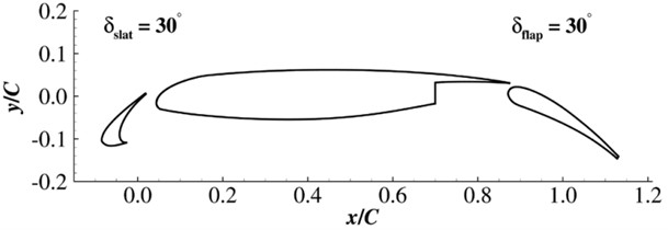
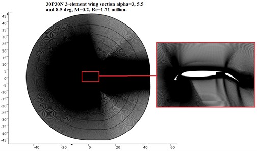
The geometric model of the wing airfoil under study is based on a three-element high-lift 30P30N configuration, including a slat, main element, and flap. The airfoil chord length is assumed to be 18 inches. The slat and flap occupy 0.15C and 0.3C of the chord length, respectively, and are deflected at an angle of 30°, which corresponds to the classic 30P30N configuration widely used in experimental studies (Fig. 1). Numerical calculations are performed within a two-dimensional aerodynamic formulation, implemented by extruding the computational domain in a third direction (along the wing span) by a unit thickness. The third dimension is introduced solely for the purpose of correct numerical implementation of the computational domain and does not assume the modeling of three-dimensional flow effects. Periodic boundary conditions are used to eliminate the influence of edge effects and simulate an infinite wing span along this direction. The use of periodic boundary conditions in the spanwise direction allows us to reproduce a quasi-two-dimensional flow and ensure homogeneity of the aerodynamic characteristics along the entire airfoil length, which is standard practice in numerical modeling of wing airfoils within the two-dimensional RANS approach. The free-stream conditions correspond to the parameters given in [6] and are characterized by a Mach number 0.2 and a Reynolds number calculated along the chord length, 1.7×10⁶. The calculations are performed for angles of attack of 3°, 5.5° and 8.5°. Non-reflecting boundary conditions are specified at the boundaries of the far-field region of the computational domain in accordance with the recommendations of [1], which minimizes the influence of the outer boundaries on the flow formation near the wing airfoil. It should be noted that a full-scale three-dimensional numerical analysis would allow for a more detailed consideration of spatial flow characteristics, including the formation of tip vortices and possible uneven distribution of flow parameters along the wing span. However, these effects are beyond the scope of this study, as the work focuses on analyzing the aerodynamic characteristics of the airfoil within a steady-state two-dimensional problem formulation. The study of three-dimensional and unsteady effects is considered a promising direction for future research aimed at in-depth understanding of the spatial structure of the flow and refining the integral aerodynamic characteristics of a multi-element configuration. The computational mesh corresponding to the airfoil geometry shown in Fig. 2 consists of 260,909 nodes, which provides sufficient spatial resolution to accurately reproduce the flow structure, boundary layer, and flow separation zones.
Fig. 2Non-structural computational mesh
To further validate the numerical strategy used, the quality of the wall mesh, and the applicability of the SST turbulence model, a classical benchmark problem of flow past a flat plate with zero pressure gradient (2D Zero Pressure Gradient Flat Plate) was considered. This problem is widely used to validate RANS models and assess the influence of the parameter on the reproduction of turbulent boundary layer structure (Fig. 3).
Fig. 3The influence of the parameter y+ on the profile of the dimensionless velocity U+ in the near-wall region
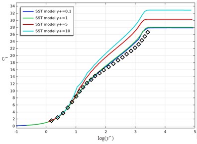
Calculations were performed using the SST model for various values of the parameter at the first wall node ( 0.1, 1, 5, and 10). Fig. 3 compares the dimensionless velocity profiles u⁺ as a function of with the reference logarithmic wall law.
As can be seen from the results, for 1, the numerical solution demonstrates good agreement with the theoretical logarithmic velocity profile, correctly reproducing both the viscous sublayer and the logarithmic boundary layer region. As increases to 5 and 10, a noticeable deviation of the numerical profiles from the reference law is observed, indicating a decrease in the accuracy of the description of the near-wall region and confirming the need to use a fine wall grid for the correct operation of the SST model. The obtained results confirm that the numerical implementation of the SST model and the chosen strategy for generating a wall grid with 1 ensure the correct reproduction of the turbulent boundary layer structure. This serves as further justification for the validity of the applied grid resolution and numerical approach used in the flow calculations around the multi-element airfoil. In the flow calculations around the three-element 30P30N airfoil in this study, the value of the y⁺ parameter for the first node near the wall was taken to be y⁺ ≈ 1, which meets the requirements of the SST turbulence model and ensures the correct reproduction of the near-wall flow region.
2.1. Mathematical model
Turbulent flow around a three-element 30P30N airfoil is described using the Reynolds-averaged Navier-Stokes (RANS) equations. This approach provides a time-averaged representation of incompressible fluid motion, enabling efficient numerical modeling of velocity and pressure fields under developed turbulence [16-18]. The use of the Reynolds-averaging procedure results in the introduction of additional terms in the equations of motion – the Reynolds stress tensor, which reflects the influence of turbulent fluctuations on momentum transfer. The introduction of closure relations for these stresses allows for the main effects of turbulence to be taken into account within a simplified computational model, while maintaining acceptable computational efficiency and stability.
The resulting mathematical model consists of a coupled set of partial differential equations, including the continuity equation, which enforces mass conservation Eq. (1) throughout the computational domain:
The momentum conservation equation Eq. (2), which describes the change in fluid velocity under the influence of external and internal forces:
where – components of the mean velocity field, – average pressure, – kinematic viscosity, – stress tensor components, – density.
Before closing the Reynolds-averaged Navier-Stokes (RANS) equations, it is necessary to model additional unknown terms associated with turbulent velocity fluctuations. As a result of averaging, a Reynolds stress tensor appears in the equations of motion, reflecting the influence of turbulent eddies on momentum transfer in the flow. This tensor contains correlations of velocity fluctuations and cannot be determined directly from the governing equations, leading to the so-called turbulence closure problem.
To overcome this difficulty, the Boussinesq hypothesis Eq. (3), based on the analogy between molecular and turbulent viscosity, is widely used:
Substituting the expression for Reynolds stresses derived from the Boussinesq hypothesis into the equations of motion allows one to take into account the effect of turbulence on momentum transfer in the averaged flow. As a result of this transformation, the Navier-Stokes equations take on a closed form Eq. (4), taking into account the effective (molecular and turbulent) viscosity, making it possible to solve them numerically using standard computational fluid dynamics methods:
To describe the influence of turbulence on the flow field around the 30P30N airfoil, a Reynolds-averaged Navier-Stokes equation model is used. The equations are discretized using the finite element method and solved in COMSOL Multiphysics. This numerical strategy allows for a detailed evaluation of the flow structure and aerodynamic characteristics associated with the airfoil’s multi-element configuration.
3. Turbulence models.
To close the RANS equations, the two-parameter Shear Stress Transport (SST) turbulence model is used Eq. (5). This model combines the advantages of two widely used turbulent models – - and - – and is based on the use of special mixing functions that provide a smooth transition between the respective formulations depending on the distance to the wall. In the near-wall region, the - model is used, allowing for the accurate reproduction of the boundary layer structure without the use of wall functions. In the outer part of the flow, a transition to the - formulation is made, which is less sensitive to the boundary conditions at the entrance to the computational domain. A key feature of the SST model is the introduction of a shear stress limiter, which prevents overestimation of turbulent viscosity in zones with an unfavorable pressure gradient and possible flow separation. This provides a more realistic description of flows with pronounced separation effects. These properties make the SST model particularly effective in analyzing high-lift wing profiles and multi-element configurations, which are characterized by intense inter-element interaction of jets, complex development of the boundary layer and local separation zones, which have a significant impact on the formation of aerodynamic characteristics [19-21]:
where is the specific turbulent kinetic energy (m2 s−2), is the specific rate of turbulent dissipation (s−1):
And the turbulent eddy viscosity is calculated using the following formula:
Each of the constants is a combination of internal (1) and external (2) constants mixed by:
where denotes constant 1, denotes constant 2. Additional functions are defined as follows:
and is the density, is the turbulent kinematic viscosity, is the molecular dynamic viscosity, is the distance from the field point to the nearest wall, and is the magnitude of the vortex motion, while:
The constants are:
Other values are presented in [19, 20].
The SST turbulence model effectively accounts for the effect of turbulent stress on airflow around a wing and provides accurate predictions of airfoil aerodynamic characteristics. This model is particularly important for analyzing multi-component wings, where the flow pattern is complex due to the interaction of multiple wing elements [21].
COMSOL Multiphysics software was used for the numerical simulations. This software platform provides powerful tools for solving CFD problems and allows for flexible configuration of model parameters. COMSOL Multiphysics supports the solution of RANS equations and the application of the SST model, delivering highly accurate results for analyzing the aerodynamic characteristics of the 30P30N airfoil.
4. Solution method
To simulate turbulent flows using the SST turbulence model, the commercial CFD software COMSOL Multiphysics was employed. The numerical formulation implemented in COMSOL Multiphysics is based on the finite element method (FEM), which is used consistently for the spatial discretization of the Reynolds-averaged Navier-Stokes equations as well as for the turbulence transport equations. No alternative numerical discretization methods were applied in the present study. The governing equations were solved in a steady-state (stationary) formulation using a segregated solution strategy. In this approach, the velocity and pressure fields were solved in a coupled segregated step, followed by a separate solution step for the turbulence variables, namely the turbulent kinetic energy k and the specific dissipation rate ω. Such a segregated strategy improves numerical stability and computational efficiency for steady RANS simulations. For the nonlinear problem, a Newton-based method with constant damping was employed. Additional numerical stabilization was achieved using pseudo-time stepping with a PID controller, which allows gradual convergence toward the steady-state solution. The initial Courant-Friedrichs-Lewy (CFL) number was set to 2 and adaptively increased up to a target value of 104, ensuring robust convergence for the considered flow conditions. The linear systems arising from the finite element discretization were solved using the direct sparse solver PARDISO, applied separately to the fluid flow variables and the turbulence variables. Automatic matrix reordering, row equilibration, and adaptive scaling of the linear equations were enabled to enhance numerical robustness. Parallel direct sparse solver options were activated to efficiently handle the large number of degrees of freedom. Convergence of the numerical solution was controlled using a relative tolerance of 10⁻3 for the stationary solver. The convergence criterion was based on the reduction of either the solution increment or the residual norm. Iterations were continued until the specified tolerance was satisfied for all solved variables, ensuring that a steady and converged solution was obtained. The described numerical setup and convergence strategy were verified through additional validation tests and provided stable and reproducible solutions for all simulated cases [22-26].
5. Results and discussion
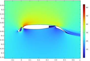
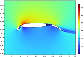
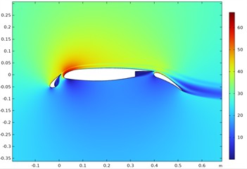
Fig. 4 shows speed contours.
A boundary layer forms near the surface of all elements, the thickness of which increases toward the trailing edge. In the gap between the slat and the main element, flow acceleration is observed, accompanied by an increase in the kinetic energy of the jet, which contributes to a delay in separation on the upper surface of the main element. As the angle of attack increases, increased velocity gradients and localized areas of flow deceleration are clearly visible in the aft section of the flap, indicating an approach to regimes with intense separation flow development. These features directly influence pressure redistribution and lift generation in a multi-element airfoil.
Fig. 4Flow velocity contours around the 30P30N airfoil
a)30°
b)5.50°
c)8.50°
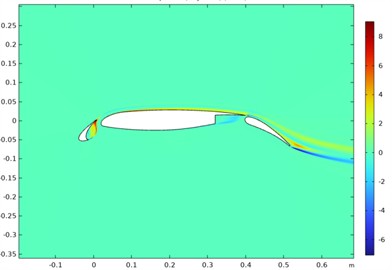
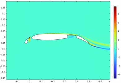
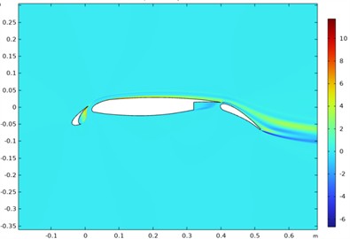
In Fig. 5 shows isolines of the Reynolds stress field around the 30P30N airfoil.
Reynolds stress distributions allow us to estimate the intensity of turbulent fluctuations and zones of increased turbulent momentum transfer. Maximum values are observed in areas with strong velocity gradients, particularly near gaps between wing elements and in jet interaction zones. Increasing the angle of attack leads to increased turbulent stress in the flap aft section, due to a thicker boundary layer and enhanced separation processes. These zones of increased turbulence have a significant impact on viscous drag and the overall aerodynamic efficiency of the airfoil.
Fig. 5Isolines of the Reynolds stress field around the 30P30N airfoil
a)30°
b)5.50°
c)8.50°
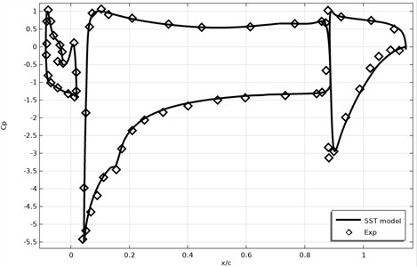
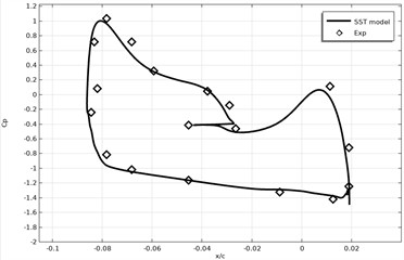
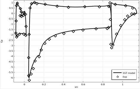
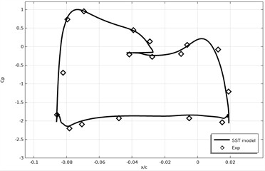
Figs 6-8 shows a comparison of the surface pressure coefficient of the 30P30N profile. The pressure coefficient is a value characterizing the pressure distribution along the surface of the wing. Visualizing this value allows you to evaluate the aerodynamic characteristics of the airfoil, such as lift, drag and stability.
As can be seen from Fig. 6 of the presented results, the numerical predictions obtained using the SST turbulence model demonstrate very good agreement with the experimental data on both the upper and lower surfaces of all airfoil elements. In particular, the rarefaction peaks in the slat and main element leading edge areas, as well as the characteristic pressure redistribution in the interaction zone between the wing elements, are correctly reproduced. Minor discrepancies between the numerical and experimental values are observed in localized areas with sharp pressure gradients, in particular near the gaps between the elements and in the aft part of the flap. These differences may be due to simplifications in the steady-state two-dimensional RANS formulation, as well as the failure to take into account three-dimensional effects and experimental pressure measurement errors. It should be noted that experimental data for the 30P30N airfoil are a widely used benchmark for validating numerical models; however, published measurements are limited in the number of available angles of attack and are not always accompanied by error information. Nevertheless, the achieved agreement in the shape of the distributions and in the level of extreme values indicates a high reliability of the numerical results.
With an increase in the angle of attack compared to the 3° regime, a general increase in the vacuum on the upper surfaces of all airfoil elements is observed, which is correctly reproduced by the SST numerical model. In particular, the peak values of in the leading region of the slat and main element, as well as the pressure redistribution in the interaction zone between the main element and the flap, are well predicted. The numerical results demonstrate good agreement with the experimental data both in the shape of the distributions and in the level of extreme values.
Fig. 6Surface pressure coefficient of coal attack profiles α= 3°
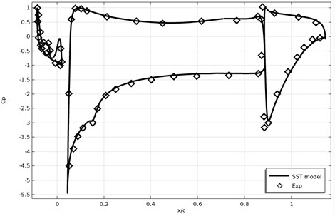
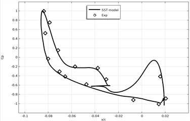
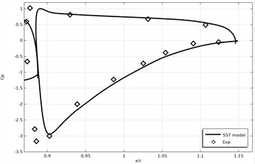
Fig. 7Surface pressure coefficient of coal attack profiles α= 5.50°
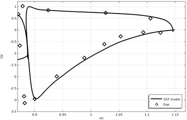
This demonstrates the ability of the stationary two-dimensional RANS-SST model to adequately describe the increase in aerodynamic effects with a moderate increase in the angle of attack. At the same time, in certain local areas, primarily near the gaps between the elements and in the rear part of the flap, small discrepancies between the calculated and experimental values are observed. These differences become more noticeable with an increase in the angle of attack and are likely associated with the increasing influence of three-dimensional effects, as well as with the limitations of the stationary two-dimensional formulation, which does not take into account the unsteady and spatial features of the flow. It should be noted that experimental data for an angle of attack of 5.5° remain a reliable benchmark for validating numerical models; however, the available information is limited to pressure coefficient distributions (Fig. 7). The lack of additional experimental data, such as detailed velocity fields or flow unsteadiness characteristics, limits the possibilities for a more in-depth quantitative analysis. Nevertheless, the achieved agreement between the numerical and experimental results confirms the validity of the chosen numerical approach and the applicability of the SST model to the flow regimes under consideration.
Fig. 8Surface pressure coefficient of coal attack profiles α= 8.5°
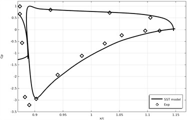
Compared to the 3° and 5.5° modes, at 8.5°, a further increase in the vacuum on the upper surfaces of the slat and main element is observed, as well as more pronounced pressure gradients in the gap zone and in the flap trailing edge. The SST numerical model generally correctly reproduces the main features of the distribution, including the position and level of the vacuum peaks, as well as the general pressure redistribution along the airfoil chord. At the same time, as the angle of attack increases, local discrepancies between the numerical and experimental data become more noticeable, primarily in areas with strong pressure gradients and the possible development of separated flows, in particular near the flap trailing edge. These discrepancies are likely due to the limitations of the stationary two-dimensional RANS-SST formulation, which does not take into account the unsteady effects and three-dimensional flow structure, which intensify at high angles of attack. It should be noted that experimental data for an angle of attack of 8.5° remain a reliable source for validation; however, under these conditions, pressure measurement errors and the influence of three-dimensional effects increase (Fig. 8). The lack of additional experimental data, such as temporal flow characteristics or spatial velocity distributions, in open sources limits the possibilities for a more detailed quantitative analysis. Overall, the achieved agreement between the numerical and experimental pressure coefficient distributions at 8.5° indicates that the numerical approach and the SST turbulence model used provide a satisfactory description of the aerodynamic characteristics of the multi-element airfoil over a wide range of angles of attack. However, the identified discrepancies indicate the need to consider three-dimensional and unsteady effects in further model development.
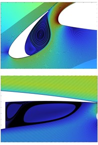
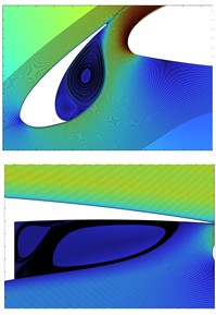
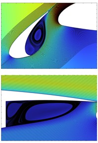
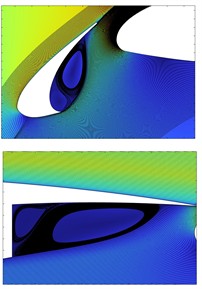
The Fig. 9 illustrates the detailed flow structure in the slat-main element gap (upper row) and in the main element-flap region (lower row) for four angles of attack: 0°, 3°, 5.5°, and 8.5°. The contour plots combined with streamline patterns allow for a qualitative assessment of boundary-layer behavior, separation zones, and recirculation development as the angle of attack increases.
Fig. 9Flow structure evolution in the slat and flap regions at different angles of attack
a)0°
b)3°
c)5.5°
d)8.5°
At 0°, the flow remains largely attached over all elements. In the slat cove region, a compact recirculation zone is observed, which is typical for multi-element high-lift configurations. This localized vortex is relatively small and stable, indicating limited separation effects. In the flap region, the flow is smoothly guided through the slot, and only a weak separation bubble is visible near the trailing edge. When the angle of attack increases to 3°, the suction on the upper surfaces intensifies, leading to stronger acceleration through the slat gap. The recirculation region within the slat cove becomes more pronounced and slightly elongated. In the flap region, the velocity gradients increase, and the separation bubble along the flap surface grows moderately in size. However, the flow remains predominantly attached, and no large-scale stall features are observed. At 5.5°, further strengthening of adverse pressure gradients can be identified. The slat cove vortex expands and shifts slightly downstream, reflecting intensified shear-layer interaction between the accelerated jet and the recirculating flow. In the flap region, the separation zone becomes more elongated, and the shear layer above the recirculation bubble becomes sharper, indicating increased turbulent mixing and momentum exchange. Despite these changes, the slot flow continues to re-energize the boundary layer over the main element and flap. For 8.5°, the flow structure exhibits clear signs of approaching more critical aerodynamic conditions. The recirculation region in the slat cove becomes larger and more vertically stretched, while the shear layer thickens. In the flap region, the separation bubble significantly enlarges and extends further downstream. The stronger adverse pressure gradient and intensified turbulence lead to more complex vortex structures, suggesting that three-dimensional and unsteady effects may become increasingly important at this angle of attack.
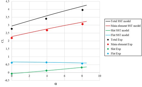
In Fig. 10 presents the variation of the lift coefficient (CL) with respect to the angle of attack () for the 30P30N three-element high-lift airfoil configuration. The results include both the total lift coefficient and the individual contributions of the main element, slat, and flap. Numerical predictions obtained using the steady two-dimensional RANS-SST turbulence model are compared with available experimental measurements [27].
A clear monotonic increase in the total lift coefficient is observed as the angle of attack increases within the considered range. This behavior is consistent with the expected aerodynamic response of a multi-element high-lift configuration operating at low and moderate angles of attack, where stall effects have not yet developed. The SST-based numerical results reproduce the overall linear trend of CL growth with increasing , demonstrating that the applied modeling approach captures the primary lift-generation mechanisms of the configuration. Quantitatively, small discrepancies between numerical and experimental values can be observed, particularly at higher angles of attack. Nevertheless, the deviation remains moderate, and the model correctly predicts the slope of the lift curve. This indicates that the SST turbulence model, combined with the finite element discretization, provides a sufficiently accurate description of the pressure redistribution and boundary-layer behavior responsible for lift production. An analysis of the individual element contributions reveals that the main element generates the dominant portion of the total lift across all examined angles of attack. Its lift contribution increases steadily with , reflecting intensified suction on the upper surface and enhanced pressure difference between the suction and pressure sides. The slat contribution, although smaller in magnitude, shows a noticeable increase with increasing angle of attack. This behavior confirms its aerodynamic role in energizing the boundary layer and delaying flow separation on the main element. The flap contribution remains relatively stable within the investigated range, providing an additional lift increment that enhances the overall aerodynamic efficiency of the configuration. The comparison between numerical and experimental data suggests that the steady two-dimensional RANS-SST approach adequately represents the aerodynamic interaction between the three elements, including jet effects in the slot regions and pressure coupling between surfaces. However, the slight increase in discrepancy at higher angles of attack may be attributed to the inherent limitations of the modeling strategy. Specifically, the present formulation does not account for three-dimensional flow structures, spanwise non-uniformities, or unsteady separation phenomena, which tend to become more pronounced as increases. Overall, the results presented in Fig. 10 confirm that the applied SST-based numerical framework provides a reliable prediction of lift characteristics for the 30P30N multi-element airfoil within the low-to-moderate angle-of-attack regime. The agreement with experimental data supports the suitability of this approach for preliminary aerodynamic analysis and performance assessment of high-lift wing configurations.
Fig. 10Wing lift coefficient
6. Conclusions
This paper presents a numerical study of the flow past a three-element high-lift 30P30N airfoil using the Reynolds-averaged Navier-Stokes equations in conjunction with the Shear Stress Transport (SST) turbulence model implemented in the COMSOL Multiphysics software environment based on the finite element method. The main scientific contribution of the study is a systematic assessment of the applicability of the finite element implementation of the steady-state two-dimensional RANS–SST model for describing the complex aerodynamics of a multi-element airfoil. Validation using experimental data demonstrated that the chosen numerical approach is capable of satisfactorily reproducing the pressure coefficient distributions on all airfoil elements and correctly reflecting the nature of lift coefficient changes in the range of low and moderate angles of attack. Analysis of the velocity fields, turbulent stress distributions, and flow interactions between the slat, main element, and flap allowed us to identify the key mechanisms shaping the aerodynamic characteristics of a multi-element configuration. The obtained results confirm that the SST model accurately reproduces the boundary layer structure and zones with elevated pressure gradients, which play a decisive role in shaping the aerodynamic characteristics of high-lift airfoils. However, the study has several limitations. The calculations were conducted within a stationary two-dimensional problem formulation, which does not allow for consideration of spatial and transient flow features, the influence of which increases with increasing angle of attack, as well as in areas of intense interelement interaction. Furthermore, quantitative verification of the model was limited by available experimental data on the pressure coefficient distribution. Information on total aerodynamic drag and the lift-to-drag ratio is insufficiently presented in open sources, limiting the possibilities for a more detailed comparison of the integrated characteristics. Given these limitations, further research should be focused on three-dimensional and transient calculations, expanding the range of angles of attack studied, and conducting a more in-depth analysis of the aerodynamic efficiency of multi-element airfoils using additional experimental data. At the same time, the results of this work show that the finite element implementation of the RANS-SST model is an effective and computationally feasible tool for preliminary analysis and verification of the aerodynamic characteristics of high-lift wings.
References
-
M. Murayama et al., “Experimental study of slat noise from 30P30N three-element high-lift airfoil in JAXA kevlar-wall low-speed wind tunnel,” in 2018 AIAA/CEAS Aeroacoustics Conference, p. 30, Jun. 2018, https://doi.org/10.2514/6.2018-3460
-
Y. Zhang, H. Chen, K. Wang, and M. Wang, “Aeroacoustic prediction of a multi-element airfoil using wall-modeled large-eddy simulation,” AIAA Journal, Vol. 55, No. 12, pp. 4219–4233, Dec. 2017, https://doi.org/10.2514/1.j055853
-
M. Sereez and U. Zaffar, “Dynamic stall on high-lift airfoil 30P30N in ground proximity,” Open Journal of Fluid Dynamics, Vol. 11, No. 3, pp. 135–152, Jan. 2021, https://doi.org/10.4236/ojfd.2021.113008
-
S. Kim, J. Alonso, and A. Jameson, “Design optimization of high-lift configurations using a viscous continuous adjoint method,” in 40th AIAA Aerospace Sciences Meeting and Exhibit, p. 844, 2002, https://doi.org/10.2514/6.2002-844
-
R. Montalà, O. Lehmkuhl, and I. Rodriguez, “On the dynamics of the turbulent flow past a three-element wing,” Physics of Fluids, Vol. 36, No. 2, Feb. 2024, https://doi.org/10.1063/5.0182215
-
K. A. Pascioni and L. N. Cattafesta, “Aeroacoustic measurements of leading-edge slat noise,” in 22nd AIAA/CEAS Aeroacoustics Conference, p. 2960, May 2016, https://doi.org/10.2514/6.2016-2960
-
K. Pascioni, L. N. Cattafesta, and M. M. Choudhari, “An experimental investigation of the 30P30N multi-element high-lift airfoil,” in 20th AIAA/CEAS Aeroacoustics Conference, p. 30, Jun. 2014, https://doi.org/10.2514/6.2014-3062
-
B. G. Arlinger and T. Larsson, “NLR 7301 two element airfoil at high lift,” Notes on Numerical Fluid Mechanics, Vol. 58, pp. 375–396, 1997.
-
E. Omer, A. Alkharboushi, and Z. Ahmed, “Numerical study of turbulent flow aerodynamics around a multi-element airfoil,” University of Zawia Journal of Engineering Sciences and Technology, Vol. 3, No. 1, pp. 26–42, Jun. 2025, https://doi.org/10.26629/uzjest.2025.03
-
Y. Zhao, H. Zhan, and B. Mi, “Full-phase leading-edge slotted-slat design and optimization for the 30p30n airfoil in takeoff, landing, and cruise conditions,” Journal of Aerospace Engineering, Vol. 39, No. 1, p. 30, Jan. 2026, https://doi.org/10.1061/jaeeez.aseng-6530
-
L. Xu, S. Wu, and Y. Chai, “Aerodynamic response of micro rotary wings in wind perturbation,” Journal of Vibroengineering, Vol. 20, No. 5, pp. 2175–2187, Aug. 2018, https://doi.org/10.21595/jve.2018.18911
-
X. Castro and Z. A. Rana, “Aerodynamic and structural design of a 2022 formula one front wing assembly,” Fluids, Vol. 5, No. 4, p. 237, Dec. 2020, https://doi.org/10.3390/fluids5040237
-
R. El Maani, S. Elouardi, B. Radi, and A. El Hami, “Study of the turbulence models over an aircraft wing,” Incertitudes et Fiabilité des Systèmes Multiphysiques, Vol. 2, No. 2, pp. 1–11, 2018, https://doi.org/10.21494/iste.op.2018.0306
-
R. Mane, K. Bhatia, S. Sharma, and R. K. Prasad, “A CFD analysis of the geometrical optimization of slotted airfoils by using the RANS k-ω SST turbulence model,” Journal of Aerospace Engineering, Vol. 38, No. 2, p. 04024118, 2025, https://doi.org/10.1061/jaeeez.aseng-5906
-
H. Zhao, Y. Yang, Y. Zhang, and W. Li, “Simulation research on the effect of Reynolds number on the Aerodynamic Characteristics of High Lift Device,” Journal of Physics: Conference Series, Vol. 2280, No. 1, p. 012010, Jun. 2022, https://doi.org/10.1088/1742-6596/2280/1/012010
-
M. Madaliev et al., “Numerical study of flow after NASA 4412 aerodynamic profile based on the SST turbulence model,” E3S Web of Conferences, Vol. 508, p. 06006, Apr. 2024, https://doi.org/10.1051/e3sconf/202450806006
-
Z. M. Malikov, M. E. Madaliev, S. L. Chernyshev, and A. A. Ionov, “Validation of a two-fluid turbulence model in Comsol multiphysics for the problem of flow around aerodynamic profiles,” Scientific Reports, Vol. 14, No. 1, p. 2306, Jan. 2024, https://doi.org/10.1038/s41598-024-52673-5
-
M. Madaliev, Z. Abdulkhaev, K. Kurpayanidi, A. Abdullayev, and A. Ilyosov, “Study of the SST turbulence model for the 2D NASA wall-mounted hump separated FLOW problem with plenum case,” E3S Web of Conferences, Vol. 508, p. 06007, Apr. 2024, https://doi.org/10.1051/e3sconf/202450806007
-
F. R. Menter, “Zonal two equation k-w turbulence models for aerodynamic flows,” in 23rd Fluid Dynamics, Plasmadynamics, and Lasers Conference, 1993, https://doi.org/10.2514/6.1993-2906
-
F. R. Menter, Turbulence, Heat and Mass Transfer 4. 2003.
-
A. Pasha, “Study of parameters affecting separation bubble size in high speed flows using k-ω turbulence model,” Journal of Applied and Computational Mechanics, Vol. 4, pp. 95–104, 2017, https://doi.org/10.22055/jacm.2017.22761.1140
-
P. K. Galenko, H. Gomez, N. V. Kropotin, and K. R. Elder, “Unconditionally stable method and numerical solution of the hyperbolic phase-field crystal equation,” Physical Review E, Vol. 88, No. 1, p. 013310, 2013, https://doi.org/10.1103/physreve.88.013310
-
M. Alnæs et al., “The FEniCS project version 1.5,” Archive of Numerical Software, Vol. 3, No. 100, 2015.
-
S. Balay, W. D. Gropp, L. C. Mcinnes, and B. F. Smith, “Efficient management of parallelism in object-oriented numerical software libraries,” in Modern Software Tools for Scientific Computing, Boston, MA: Birkhäuser Boston, 1997, pp. 163–202, https://doi.org/10.1007/978-1-4612-1986-6_8
-
S. K. Mkhonta, K. R. Elder, and Z.-F. Huang, “Exploring the complex world of two-dimensional ordering with three modes,” Physical Review Letters, Vol. 111, No. 3, p. 035501, Jul. 2013, https://doi.org/10.1103/physrevlett.111.035501
-
P. K. Galenko and K. R. Elder, “Marginal stability analysis of the phase field crystal model in one spatial dimension,” Physical Review B, Vol. 83, No. 6, p. 064113, 2011, https://doi.org/10.1103/physrevb.83.064113
-
L. Zhang et al., “Stall characteristics and circulation control of internally blown flap,” Acta Aerodynamica Sinica, Vol. 39, No. 5, pp. 53–62, 2021.
About this article

The authors have not disclosed any funding.
The authors would like to express their sincere appreciation to Professor Zafar Mamatkulovich Malikov of the Fluid Mechanics Laboratory for his valuable guidance, encouragement, and continuous support. His enthusiasm for turbulence research and insightful discussions significantly contributed to the motivation and direction of this study.
The datasets generated during and/or analyzed during the current study are available from the corresponding author on reasonable request.
Murodil Madaliev: conceptualization, methodology development, numerical simulations using COMSOL Multiphysics, and writing of the original draft. Jamolddin Akhmedov: theoretical analysis and interpretation of the results. Akhror Akramov and Islomjon Tohirov: validation of the results through comparison with experimental data and data curation. Odiljon Odilov: provision of resources, including literature review and technical data. Ulugbek Abdurakhmonov: review and editing of the manuscript, as well as formulation of final conclusions.
The authors declare that they have no conflict of interest.

