Abstract
Existing motorcycle aerodynamic studies focus primarily on determining the aerodynamic drag coefficient or conducting experimental wind tunnel studies. Detailed analysis of the flow structure, turbulent kinetic energy distribution, and flow characteristics in various cross-sections of the computational domain using open CFD platforms is underrepresented. Furthermore, the literature provides a limited number of studies comprehensively analyzing the evolution of vortex structures behind a motorcycle using the SST turbulence model in the OpenFOAM environment. This paper presents a numerical study of the aerodynamic characteristics of a motorcycle using the OpenFOAM software package based on the RANS system of equations in conjunction with the SST turbulence model. To solve the discretized equations, the SIMPLE algorithm was used in conjunction with the GAMG multigrid solver, ensuring stability and accelerated convergence of the computational process. The distributions of the velocity, pressure, and turbulent kinetic energy fields in the longitudinal and transverse cross-sections of the computational domain were obtained. The analysis revealed flow stagnation zones, low-pressure areas, and the formation of recirculation structures behind the motorcycle, which significantly influence aerodynamic drag. The scientific novelty of this study lies in a comprehensive, layer-by-layer analysis of the turbulent flow structure around the motorcycle's full geometry, with a detailed study of the distribution of turbulent kinetic energy in various cross-sections using the open-source OpenFOAM software. The results obtained can be used in further aerodynamic optimization of the motorcycle design to reduce drag and improve stability.
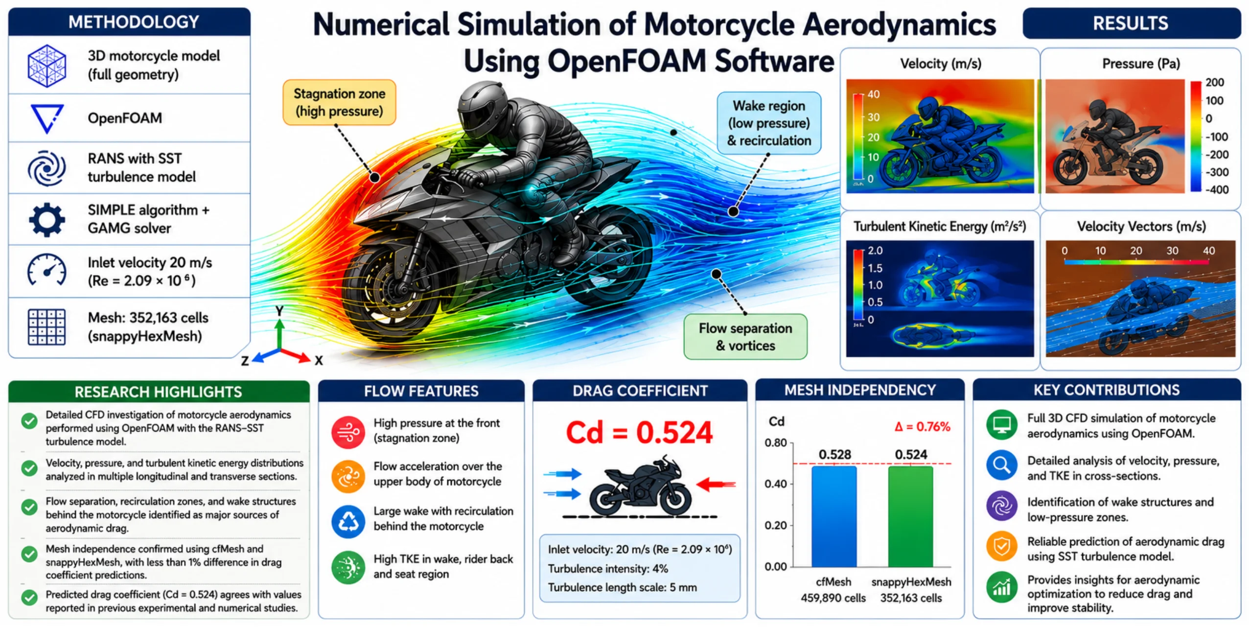
Highlights
- A detailed CFD investigation of motorcycle aerodynamics was performed using OpenFOAM and the RANS-SST turbulence model.
- Velocity, pressure, and turbulent kinetic energy distributions were analyzed in multiple longitudinal and transverse sections.
- Flow separation, recirculation zones, and wake structures behind the motorcycle were identified as major sources of aerodynamic drag.
- Mesh independence was verified using cfMesh and snappyHexMesh, with less than 1% deviation in drag coefficient predictions.
- The computed drag coefficient (Cd = 0.524) agrees well with values reported in previous experimental and numerical studies.
1. Introduction
Aerodynamics plays a crucial role in modern vehicle engineering, directly affecting energy efficiency, stability, controllability, and overall dynamic performance. Reference [1] provides a comprehensive review of active aerodynamic systems for road vehicles [1], where the importance of drag reduction and stability enhancement is emphasized. The feasibility of fan-driven devices generating additional downforce is investigated in [2], demonstrating the role of aerodynamic load control in vehicle performance. Balanced aerodynamic axle loading through innovative aerodynamic components is analyzed in [3], highlighting the influence of geometry on aerodynamic forces.
Motorcycle aerodynamics presents additional complexity due to its open structure and strong rider-vehicle interaction. A comprehensive CFD simulation of a sport motorcycle is reported in [4], where detailed flow visualization was used to identify separation zones and wake structures.
Advanced CFD methods are widely used to investigate complex aerodynamic phenomena. Fluid-structure interaction effects in competitive vehicles are analyzed in [5], revealing the coupling between aerodynamic forces and vehicle dynamics. Unsteady aerodynamic effects during braking maneuvers are studied in [6], demonstrating the importance of transient flow modeling. The influence of different plate arrangements on car body aerodynamics is examined in [7], confirming that geometric modifications significantly alter flow structures.
Specific investigations of motorcycle aerodynamics are presented in [8], where aerodynamic kits for racing motorcycles were analyzed. Earlier experimental and CFD-based studies reported in [9] and [10] demonstrated the effectiveness of numerical simulations in predicting aerodynamic characteristics of two-wheeled vehicles.
Recent developments in turbulence modeling have further improved CFD accuracy. A two-fluid turbulence model for mixing layer simulations is proposed in [11]. Axisymmetric jet simulations using advanced turbulence modeling are presented in [12]. Higher-order accuracy schemes for flow over flat plates are investigated in [13]. Turbulent mixing using the SST model is analyzed in [14], confirming its robustness in complex flow conditions. Methods for improving numerical solution accuracy are discussed in [15]. A comparison of linear and nonlinear RANS turbulence models is presented in [16], demonstrating differences in predictive performance. Turbulent flow modeling in a centrifugal separator is investigated in [17], validating RANS-based approaches for complex flow systems.
In addition, numerical investigations of fluid-structure interaction and vibration behavior of curved panels and shells have been reported in [18] and [19], where finite element methods were applied to study coupled fluid and structural responses. These works highlight the importance of considering interaction effects between aerodynamic loads and structural behavior in advanced engineering systems. Although the present study focuses on steady external aerodynamics without structural deformation modeling, the mentioned investigations provide a broader methodological background for coupled aerodynamic-structural analyses.
Despite these contributions, the existing literature reveals a limitation: most motorcycle-related studies primarily focus on drag coefficient estimation or global aerodynamic performance indicators, while detailed sectional analysis of velocity, pressure, and turbulent kinetic energy distributions using open-source CFD platforms remains insufficiently explored. In particular, comprehensive investigation of wake evolution and turbulence structure behind a full motorcycle geometry using the SST model within OpenFOAM has not been systematically addressed.
Therefore, the present study aims to perform a detailed numerical investigation of airflow around a motorcycle using the Reynolds-Averaged Navier-Stokes (RANS) equations coupled with the SST turbulence model implemented in OpenFOAM. The SIMPLE algorithm and GAMG solver are employed to ensure numerical stability and convergence. Special attention is devoted to sectional analysis of velocity, pressure, and turbulent kinetic energy fields to identify key flow structures influencing aerodynamic resistance. This work contributes to the advancement of numerical modeling approaches for motorcycle aerodynamics and provides a structured flow analysis framework suitable for further aerodynamic optimization.
2. Physical and mathematical formulation of the problem
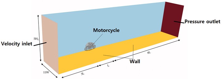
The dimensions of the fluid domain were defined according to the numerical modeling guidelines to ensure a complete representation of the flow structures formed behind the moving motorcyclist. This approach avoids the influence of boundary conditions on the airflow behavior. For all considered cases, the computational domain dimensions were height (5 H1), width (11 W) and length (12 L), as illustrated in Fig. 1.
Fig. 1Dimensions of the computational domain
In the present study, the tire-ground interaction was modeled using a simplified steady-state approach. The ground surface was treated as a stationary no-slip wall, and the motorcycle wheels were modeled as rigid bodies without rotational motion. This assumption corresponds to a simplified aerodynamic configuration commonly adopted in steady external flow simulations. Although the rotating wheel and moving ground effects may influence near-wall flow structures and local shear stresses, their impact on the global aerodynamic drag coefficient is generally limited for steady-state RANS simulations. The adopted approach allows isolation of the primary aerodynamic features related to body geometry and wake formation. Future work may include rotating wheel modeling and moving ground boundary conditions to capture more detailed near-ground flow behavior. At the domain inlet, the following parameters were defined: velocity magnitude of 20 m/s, turbulence intensity of 4 % and turbulence length scale of 5 mm. The corresponding Reynolds number based on the height of the studied geometry (H1) and the inlet velocity is 2.09×10⁶. The computational grid is shown in Fig. 2. The inlet velocity of 20 m/s was selected to represent a typical operating speed of a motorcycle under standard driving conditions (approximately 72 km/h), ensuring realistic aerodynamic loading. The Reynolds number corresponding to this velocity ( 2.09×10⁶) confirms that the flow regime is fully turbulent. The turbulence intensity at the inlet was set to 4 %, which corresponds to moderate external atmospheric turbulence levels commonly used in external aerodynamic simulations. The turbulence length scale was defined based on characteristic geometric dimensions of the motorcycle to ensure consistent turbulence modeling at the inlet boundary. The SST turbulence model was selected due to its proven capability to accurately predict adverse pressure gradients and flow separation, which are dominant features in motorcycle aerodynamics. Compared to the standard - model, SST provides improved near-wall resolution and more reliable wake prediction. The SIMPLE algorithm was employed for pressure-velocity coupling because of its robustness in steady-state incompressible simulations. Under-relaxation factors and solver tolerances were chosen to ensure stable convergence while maintaining computational efficiency. Thus, all model parameters were selected based on physical reasoning, flow regime characteristics, and established CFD best practices for external aerodynamic simulations.
Fig. 2Non-structural computational grid
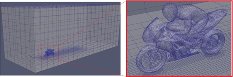
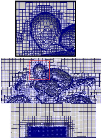
Fig. 3 presents a comparison between two different computational grids generated for the motorcycle aerodynamic simulations: cfMesh and snappyHexMesh. The cfMesh configuration consists of approximately 459,890 cells, while the snappyHexMesh grid contains approximately 352,163 cells. Both meshes are based on predominantly hexahedral elements with local refinement applied in regions of high geometric complexity and expected flow gradients.
Fig. 3Comparison of computational meshes generated using cfMesh and snappyHexMesh
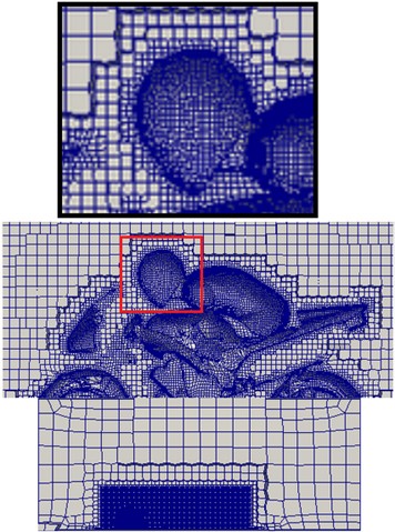
a) CF Mesh
b) Snappy Mesh
The cfMesh grid demonstrates a more uniformly distributed refinement throughout the computational domain, whereas the snappyHexMesh grid exhibits stronger local refinement around the motorcycle body, wheels, and wake region. In both cases, near-wall refinement is introduced to improve resolution of boundary layer effects and accurately capture flow separation and recirculation zones. To assess the sensitivity of the results to the mesh discretization type, a comparative analysis of the aerodynamic drag coefficient () was performed. For the cfMesh mesh, = 0.528 was obtained, while for snappyHexMesh, = 0.524. The relative discrepancy between the results is less than 1 % (≈ 0.76 %), indicating the mesh independence of the obtained results and confirming the numerical stability of the model. Given comparable accuracy and a more rational distribution of computational resources, the mesh generated by the snappyHexMesh method was used for the final calculations. The obtained drag coefficient falls within the range reported in previous experimental and numerical investigations of sport motorcycles ( ≈ 0.50-0.60), confirming the physical consistency of the numerical model.
Unlike many previous studies that primarily focused on global aerodynamic coefficients, the present work provides a detailed sectional analysis of velocity, pressure, and turbulent kinetic energy distributions in multiple vertical and horizontal planes. The comparative evaluation of two independent mesh generation approaches (cfMesh and snappyHexMesh) further strengthens the numerical reliability of the results and represents an additional contribution of this study. However, several limitations should be acknowledged. The simulations were performed under steady-state conditions using the RANS–SST turbulence model, which may not fully capture unsteady vortex shedding and transient wake dynamics. Structural deformation and fluid–structure interaction effects were not considered. Furthermore, crosswind effects and rotating wheel modeling were simplified, which may influence detailed flow behavior. Future work will address these aspects to improve predictive capability.
3. Mathematical model
To investigate the aerodynamic characteristics of the motorcycle, the incompressible Reynolds-averaged Navier–Stokes (RANS) equations were employed. These equations describe the conservation of mass and momentum for turbulent flows by decomposing instantaneous flow variables into mean and fluctuating components according to Reynolds decomposition. This averaging procedure introduces additional terms representing Reynolds stresses, which account for turbulence effects [14-17].
For incompressible flow, the continuity equation is written as:
which ensures mass conservation within the computational domain. The momentum conservation equation in RANS form is expressed as:
where – components of the mean velocity field, – average pressure, – kinematic viscosity, – stress tensor components, – density.
To close the system of equations, the Boussinesq hypothesis is adopted, which relates the Reynolds stresses to the mean strain rate through an eddy viscosity concept:
where 𝜈𝑡 is the turbulent (eddy) viscosity, 𝑘 is the turbulent kinetic energy, and 𝛿𝑖𝑗 is the Kronecker delta.
In the present study, the Shear Stress Transport (SST) turbulence model was used to determine the turbulent viscosity.
4. Turbulence models
The Reynolds-averaged Navier-Stokes (RANS) equations are used to numerically simulate complex turbulent flows that occur when flowing around objects. These equations contain additional terms that describe turbulent stresses caused by velocity fluctuations. A turbulence model is used to close them. In this study, the Shear Stress Transport (SST) model [18-20] was chosen, which combines the advantages of the k-ω and k-ε models. This combination allows achieving high accuracy in modeling flows in both boundary layer regions and flow separation zones, which makes it an optimal choice for studying the aerodynamics of complex geometric shapes:
where is the specific turbulent kinetic energy (m2 s−2), is the specific rate of turbulent dissipation (s−1). represents the production of turbulent kinetic energy, and is a blending function that ensures smooth transition between - and - formulations. Other values are presented in [18-19].
The turbulent viscosity is computed as:
where is the strain rate magnitude and is the second blending function of the SST model. The combined RANS-SST formulation enables accurate prediction of adverse pressure gradients, separation zones, and wake structures, which are critical for analyzing motorcycle aerodynamics. This mathematical framework provides a reliable basis for resolving complex turbulent flow behavior around bluff bodies with strong recirculation regions.
5. Method of solution
For numerical modeling of motorcycle aerodynamics in the OpenFOAM environment, the finite volume method was applied to discretize the Reynolds-averaged Navier-Stokes (RANS) equations together with the SST turbulence transport equations, transforming the governing differential equations into a system of algebraic equations solved iteratively under steady-state conditions. Spatial discretization was performed using second-order accurate schemes, including bounded Gauss linearUpwind for the momentum convection term, bounded upwind schemes for turbulence variables, and Gauss linear corrected schemes for diffusive terms to account for mesh non-orthogonality, ensuring a balance between numerical stability and accuracy. Pressure-velocity coupling was achieved using the consistent SIMPLE algorithm, while the pressure equation was solved using the GAMG multi-grid solver with Gauss-Seidel smoothing to accelerate convergence, and the velocity and turbulence equations were solved using a smoothSolver with appropriate tolerances (10⁻7-10⁻8). Under-relaxation factors were applied (0.9 for velocity and 0.5 for turbulence variables) to maintain stable iterative behavior. Convergence was monitored through residual reduction of pressure, velocity, turbulent kinetic energy (), and specific dissipation rate (), and the solution was considered converged when residuals reached the prescribed tolerances and stabilized, ensuring numerical reliability and stable resolution of the turbulent flow structures around the motorcycle geometry.
6. Results and discussion
Fig. 4 presents the structured workflow of the numerical investigation of motorcycle aerodynamics performed in this study. The research process begins with problem definition and formulation of the aerodynamic objectives. Subsequently, a three-dimensional CAD model of the motorcycle is prepared, followed by the generation of the computational domain designed to minimize boundary influence on the flow field. An unstructured computational mesh is then generated, and grid quality together with grid independence verification is performed to ensure numerical reliability. After defining appropriate boundary conditions, the physical model is selected, namely the Reynolds-Averaged Navier–Stokes (RANS) equations coupled with the Shear Stress Transport (SST) turbulence model. The numerical solution is implemented using the SIMPLE pressure-velocity coupling algorithm and the GAMG solver to ensure stable and efficient convergence. Residual monitoring and convergence assessment are carried out to confirm solution accuracy. The final stages include post-processing of velocity, pressure, and turbulent kinetic energy (TKE) fields, detailed flow structure analysis, and aerodynamic interpretation of the obtained results. The presented workflow ensures methodological consistency, numerical stability, and systematic evaluation of aerodynamic characteristics.
Fig. 4Structured diagram of the numerical study of motorcycle aerodynamics
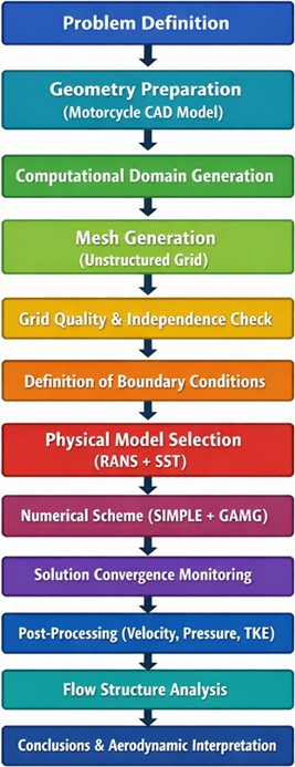
Fig. 5 shows the velocity isolines and streamlines in the central plane of the geometry. These graphical data allow visualization of the flow velocity distribution and its characteristic behavior in the flow region, including zones with changes in velocity and streamline direction.
Fig. 5Velocity isolines [m/s] and streamlines in the central plane of geometry
![Velocity isolines [m/s] and streamlines in the central plane of geometry](https://static-01.extrica.com/articles/25930/25930-img6.jpg)
![Velocity isolines [m/s] and streamlines in the central plane of geometry](https://static-01.extrica.com/articles/25930/25930-img7.jpg)
Fig. 6Velocity isolines [m/s] and streamlines in two (z= 0.5, 1 m) horizontal planes located above ground level
![Velocity isolines [m/s] and streamlines in two (z= 0.5, 1 m) horizontal planes located above ground level](https://static-01.extrica.com/articles/25930/25930-img8.jpg)
![Velocity isolines [m/s] and streamlines in two (z= 0.5, 1 m) horizontal planes located above ground level](https://static-01.extrica.com/articles/25930/25930-img9.jpg)
a)0.5 m
![Velocity isolines [m/s] and streamlines in two (z= 0.5, 1 m) horizontal planes located above ground level](https://static-01.extrica.com/articles/25930/25930-img10.jpg)
![Velocity isolines [m/s] and streamlines in two (z= 0.5, 1 m) horizontal planes located above ground level](https://static-01.extrica.com/articles/25930/25930-img11.jpg)
b)1 m
At the front of the motorcycle, a stagnation region is observed, characterized by a decrease in velocity and an increase in static pressure. As the flow passes over the upper and side surfaces, it accelerates, forming regions of increased velocity due to pressure redistribution along the flowed surface. Behind the motorcycle, a flow separation zone and the formation of a wake region are clearly visible, characterized by reduced velocity and the presence of vortex structures. Streamlines demonstrate the development of recirculation zones in the rear of the structure, indicating a significant contribution of pressure to the formation of aerodynamic drag. Maximum velocity gradients are observed near the streamlined edges and in the flow-rider interaction zone, highlighting the influence of geometry on the flow structure. The obtained results correspond to the typical pattern of turbulent flow around complex-shaped bodies at a Reynolds number of approximately 106 and confirm the correctness of the chosen numerical model.
Fig. 6 shows the velocity isolines and streamlines in two (0.5, 1 m) horizontal planes located above ground level. These data allow us to analyze the velocity distribution and the nature of the flow near the surface, as well as to evaluate the influence of geometry on the aerodynamic properties in different layers of the flow.
At 0.5 m, a pronounced zone of decelerated flow is observed immediately behind the rear of the motorcycle, accompanied by the formation of an extended wake region. This region exhibits reduced velocity values and intense vortex formation, indicating the presence of flow separation and recirculation structures. The wake width at this height is quite large, indicating a significant contribution of pressure to the overall aerodynamic drag. At 1 m, the zone of reduced velocity becomes narrower and elongated in the direction of the flow. The intensity of the vortex structures decreases, indicating a gradual recovery of the flow and a reduction in turbulent effects away from the road surface. This confirms the three-dimensional nature of the flow and the spatial redistribution of turbulent energy. A comparison of the two sections shows that the greatest influence of the motorcycle's geometry on the flow structure occurs near the mid-height of the body, while the flow recovers more quickly in the upper layers. The obtained results correspond to the characteristic features of turbulent flow around complex-shaped bodies at high Reynolds numbers and confirm the correctness of the numerical model.
Fig. 7 shows the pressure isolines in the central plane passing through the axis of symmetry of the geometry.
Fig. 7Pressure contours [Pa] in the central plane
![Pressure contours [Pa] in the central plane](https://static-01.extrica.com/articles/25930/25930-img12.jpg)
These data demonstrate the pressure distribution over the surface of the object and in the flow area. The results indicate that high-pressure zones caused by the oncoming flow are formed in the front part of the motorcycle, while low-pressure zones characteristic of flow separation zones are observed behind the motorcycle. Such an analysis allows us to identify areas that significantly affect aerodynamic drag and serves as a basis for further optimization of the design shape [12, 21, 22].
Fig. 8 shows the isolines of the kinetic energy of turbulence in the central plane and at a height of 1 meter above the ground.
These graphs illustrate the distribution of turbulent kinetic energy in different parts of the flow, including areas of intense turbulence. In the central plane, areas with increased kinetic energy of turbulence can be observed, indicating the presence of strong turbulent phenomena, especially in the flow separation areas behind the motorcycle. At a height of 1 meter above the ground, in turn, the distribution of kinetic energy shows changes in the intensity of turbulent vortices and their influence on the behavior of the flow in the upper layers. These data are important for analyzing the stability of the flow and optimizing the aerodynamic characteristics of the object. Fig. 9 shows a 3D flow line illustrating the trajectories of air particles around the object.
Fig. 8Isolines of kinetic energy of turbulence in the central plane and at a height of 1 meter above the ground
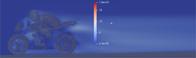
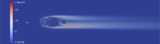
Fig. 9A 3D flow line illustrating the trajectories of air particles around an object
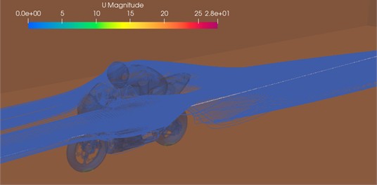
A stagnation zone forms at the front of the motorcycle, where the flow velocity decreases due to the impact of the oncoming flow with the surface of the structure. As the flow passes over the upper body and the rider, it accelerates due to pressure redistribution and the formation of longitudinal velocity gradients. At the rear of the structure, the development of an extended wake region is clearly visible, characterized by reduced velocity and the presence of vortex structures. Streamlines demonstrate the formation of stable recirculation zones behind the motorcycle's tail, indicating a significant contribution of pressure to the overall aerodynamic drag. The spatial nature of the vortex structures confirms the three-dimensional nature of the flow and the complexity of the flow’s interaction with the geometry of the object. The obtained results correspond to the typical pattern of turbulent flow around complex-shaped bodies at high Reynolds numbers and confirm the adequacy of the chosen numerical model for analyzing the motorcycle’s aerodynamic characteristics.
Fig. 10 shows changes in velocity and turbulent kinetic energy at distances of 2, 3, 4, 5 meters in the central area.
These results allow analysis of the flow behavior and turbulent effects at different distances from the object. The changes in velocity demonstrate how the flow speeds up or slows down depending on the distance from the object, and also reveal areas of high and low velocity, including areas of turbulent separation. Analysis of the kinetic energy of turbulence at the same distances allows us to estimate the intensity of turbulent vortices and their influence on the flow structure in different sections, which is important for assessing aerodynamic drag and other flow characteristics.
Fig. 10Changes in velocity and turbulent kinetic energy at distances x= 2, 3, 4, 5 meters in the central region
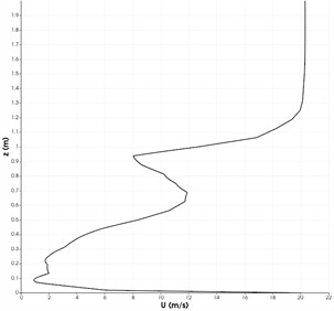
a) Velocity changes: 2 m
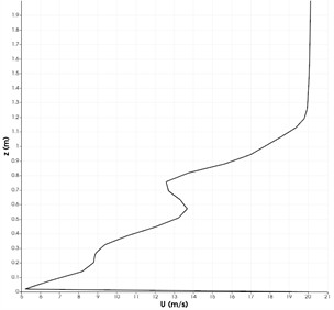
b) Velocity changes: m
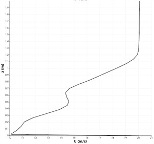
c) Velocity changes: m
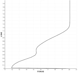
d) Velocity changes: 5 m
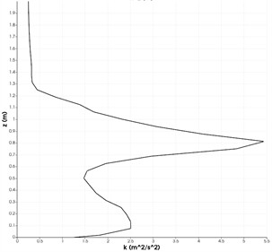
e) Changes in turbulent kinetic energy: 2 m
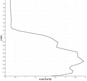
f) Changes in turbulent kinetic energy: 3 m
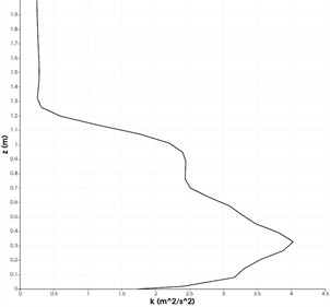
g) Changes in turbulent kinetic energy: 4 m
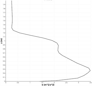
h) Changes in turbulent kinetic energy: 5 m
7. Conclusions
In this study, a detailed numerical investigation of motorcycle aerodynamics was performed using the Reynolds-averaged Navier-Stokes (RANS) equations coupled with the Shear Stress Transport (SST) turbulence model implemented in the OpenFOAM environment. The adopted numerical framework enabled comprehensive analysis of velocity, pressure, and turbulent kinetic energy distributions in both vertical and horizontal sections of the computational domain. The simulations revealed the formation of a stagnation region at the frontal area of the motorcycle, accelerated flow along the upper surfaces, and a pronounced wake region characterized by flow separation and recirculation behind the vehicle. The wake structure was identified as the dominant contributor to aerodynamic drag due to significant pressure deficit in the rear region. The computed drag coefficient ( = 0.524) falls within the range reported in previous experimental and numerical studies of sport motorcycles, confirming the physical consistency of the model. A mesh sensitivity analysis conducted using two independent grid generation approaches (cfMesh and snappyHexMesh) demonstrated a deviation of less than 1 % in Cd values, confirming the grid independence and numerical robustness of the solution. The SST turbulence model proved effective in resolving boundary layer behavior and separation zones, which are critical for accurate prediction of aerodynamic forces at Reynolds numbers on the order of 106. The numerical methodology provides a stable and reliable framework for analyzing complex turbulent flows around bluff bodies. From an engineering and industrial perspective, the results offer practical guidance for aerodynamic optimization of motorcycle geometry, particularly in reducing wake size and pressure drag. The presented open-source CFD approach provides a cost-effective alternative to wind tunnel testing and can be applied during early design stages to improve fuel efficiency, high-speed stability, and overall aerodynamic performance. Overall, this study contributes to the advancement of numerical modeling techniques in vehicle aerodynamics and establishes a validated computational framework suitable for further optimization studies and industrial applications.
References
-
J. Piechna, “A review of active aerodynamic systems for road vehicles,” Energies, Vol. 14, No. 23, p. 7887, Nov. 2021, https://doi.org/10.3390/en14237887
-
M. Szudarek, A. Piechna, and J. Piechna, “Feasibility study of a fan-driven device generating downforce for road cars,” Energies, Vol. 15, No. 15, p. 5549, Jul. 2022, https://doi.org/10.3390/en15155549
-
M. Szudarek, K. Kamieniecki, S. Tudruj, and J. Piechna, “Towards balanced aerodynamic axle loading of a car with covered wheels-inflatable splitter,” Energies, Vol. 15, No. 15, p. 5543, 2022, https://doi.org/10.3390/en15155543
-
K. Wiński and A. Piechna, “Comprehensive CFD aerodynamic simulation of a sport motorcycle,” Energies, Vol. 15, No. 16, p. 5920, Aug. 2022, https://doi.org/10.3390/en15165920
-
J. Broniszewski and J. R. Piechna, “Fluid-structure interaction analysis of a competitive car during brake-in-turn manoeuvre,” Energies, Vol. 15, No. 8, p. 2917, Apr. 2022, https://doi.org/10.3390/en15082917
-
J. Broniszewski and J. Piechna, “A fully coupled analysis of unsteady aerodynamics impact on vehicle dynamics during braking,” Engineering Applications of Computational Fluid Mechanics, Vol. 13, No. 1, pp. 623–641, 2019, https://doi.org/10.1080/19942060.2019.1616326
-
K. Kurec, K. Kamieniecki, and J. Piechna, “Influence of different plates arrangements on the car body,” Energies, Vol. 15, No. 2, p. 619, Jan. 2022, https://doi.org/10.3390/en15020619
-
M. Palanivendhan, D. Nagpal, D. Ayush Rao, J. Philip, and M. Srinivas Ganapathi, “Design and analysis of an aerodynamic kit for a two wheeled race motorcycle,” Materials Today: Proceedings, Vol. 45, pp. 7239–7246, 2021, https://doi.org/10.1016/j.matpr.2021.02.635
-
M. Angeletti, L. Sclafani, G. Bella, and S. Ubertini, “The role of CFD on the aerodynamic investigation of motorcycles,” in SAE Technical Paper Series, Vol. 1, 2003, https://doi.org/10.4271/2003-01-0997
-
G. Bella, S. Ubertini, and U. Desideri, “Experimental and computational analysis of the aerodynamic performances of a maxi-scooter,” in SAE Technical Paper Series, Vol. 1, 2003, https://doi.org/10.4271/2003-01-0998
-
Z. M. Malikov, A. A. Mirzoev, M. E. Madaliev, N. J. Khujatov, and E. S. Buriev, “Numerical simulation of the layer mixing problem based on a new two-fluid turbulence model,” in Mechanical Science and Technology Update, Vol. 53, No. 2, pp. 192–202, 2022, https://doi.org/10.25206/978-5-8149-3453-6-2022-192-202
-
Z. M. Malikov, M. E. Madaliev, D. P. Navruzov, and K. Adilov, “Numerical study of an axisymmetric jet based on a new two-fluid turbulence model,” in AIP Conference Proceedings, Vol. 2637, No. 1, p. 040023, Jan. 2022, https://doi.org/10.1063/5.0118473
-
M. Madaliev, E. Yunusaliev, A. Usmanov, N. Usmonova, and K. Muxammadyoqubov, “Numerical study of flow around flat plate using higher-order accuracy scheme,” E3S Web of Conferences, Vol. 365, p. 01011, Jan. 2023, https://doi.org/10.1051/e3sconf/202336501011
-
E. Madaliev, M. Madaliev, S. Raxmankulov, and S. Raxmonkulova, “Turbulent mixing of two plane flows based on the SST turbulence model,” E3S Web of Conferences, Vol. 452, p. 02012, Nov. 2023, https://doi.org/10.1051/e3sconf/202345202012
-
Z. M. Malikov, M. E. Madaliev, S. L. Chernyshev, and A. A. Ionov, “Validation of a two-fluid turbulence model in comsol multiphysics for the problem of flow around aerodynamic profiles,” Scientific Reports, Vol. 14, No. 1, p. 2306, Jan. 2024, https://doi.org/10.1038/s41598-024-52673-5
-
M. Madaliev et al., “Comparison of numerical results of linear and nonlinear turbulence models based on the rans approach,” E3S Web of Conferences, Vol. 587, p. 01003, Nov. 2024, https://doi.org/10.1051/e3sconf/202458701003
-
Z. M. Malikov and M. E. Madaliev, “Mathematical modeling of a turbulent flow in a centrifugal separator,” Vestnik Tomskogo Gosudarstvennogo Universiteta. Matematika-Mekhanika, No. 71, pp. 121–138, Jan. 2021, https://doi.org/10.17223/19988621/71/10
-
F. Menter, “Zonal two equation k-w turbulence models for aerodynamic flows,” in 23rd Fluid Dynamics, Plasmadynamics, and Lasers Conference, p. 1993-2906, 1993, https://doi.org/10.2514/6.1993-2906
-
F. R. Menter, M. Kuntz, and R. Langtry, “Ten years of industrial experience with the SST turbulence model,” in Turbulence, heat and mass transfer 4, Vol. 4, Begell House, Inc., 2003, pp. 625–632.
-
A. A. Pasha, “Study of parameters affecting separation bubble size in high speed flows using k-ω turbulence model,” Journal of Applied and Computational Mechanics, Vol. 4, No. 2, pp. 95–104, 2018.
-
D. M. Mukhammadiev, K. A. Akhmedov, I. O. Ergashev, L. Y. Zhamolova, and T. D. Mukhammadiev, “Study of rib bending at installation of insertion into rib,” Proceedings of Higher Education Institutions. Textile Industry Technology, Vol. 1, No. 1, pp. 277–281, 2022, https://doi.org/10.47367/0021-3497_2022_1_277
-
K. Nilufar, “Numerical simulation of aerodynamic flow around a building using OpenFOAM software,” Journal of Construction and Engineering Technology, Vol. 3, No. 2, pp. 8–14, 2025, https://doi.org/10.24412/2181-4473-2025.3.202
About this article

The authors have not disclosed any funding.
The authors would like to express their sincere gratitude to Professor Zafar Malikov for his guidance and support, as well as for inspiring their interest in turbulence research.
The datasets generated during and/or analyzed during the current study are available from the corresponding author on reasonable request.
Murodil Madaliev: conceptualization of the research problem, development of the numerical and methodological framework, supervision of the OpenFOAM-based computational study, and critical review and final approval of the manuscript. Bobur Bakhtiyorov: systematic review and synthesis of the scientific literature on motorcycle aerodynamics, preparation of the theoretical background, participation in data organization, and validation of the numerical findings. Jamshid Obidov: development of the computational domain, generation and refinement of high-quality meshes, implementation of numerical solvers, execution of CFD simulations using OpenFOAM, and contribution to the formal analysis of the results. Qakhramon Masodiqov: specification of boundary and initial conditions, selection and calibration of turbulence models, methodological support for numerical stability and convergence, and participation in result validation. Jamshid Akramov: post-processing and visualization of aerodynamic fields, detailed analysis of pressure, velocity, and wake structures, interpretation of flow characteristics, and contribution to the critical revision of the manuscript. Zokhidjon Abdulkhaev: preparation of the original manuscript draft, organization and structuring of the scientific content, coordination of revisions among co-authors, and technical editing of the final version.
The authors declare that they have no conflict of interest.

