Abstract
Efficient water management is a key requirement for the sustainability of modern agroecological systems, particularly in drip irrigation networks where emitter clogging caused by suspended solids remains a critical problem. Centrifugal hydrocyclones represent an energy-efficient and low-maintenance pre-filtration technology that separates solid particles from irrigation water without using filter media. However, the optimization of hydrocyclone design for small-scale irrigation applications requires a comprehensive understanding of internal hydrodynamics and particle behavior. In this study, a novel high-efficiency centrifugal hydrocyclone was developed and compared with a conventional design using three-dimensional CFD simulations in COMSOL Multiphysics 6.1. The turbulence model was employed to accurately resolve near-wall effects and capture the vortex-core dynamics, while the motion of suspended particles was simulated using a Lagrangian particle-tracking approach. The numerical results reveal that the proposed design improves the separation efficiency by up to 71 % compared to the classical configuration, with only a marginal increase (≈ 3 %) in pressure drop. The enhanced flow symmetry and stabilized vortex structure in the new hydrocyclone contribute to more uniform velocity and pressure distributions. These findings demonstrate the effectiveness of the proposed model in improving water quality and operational reliability of drip irrigation systems, offering practical implications for sustainable water management in agroecological applications.
Highlights
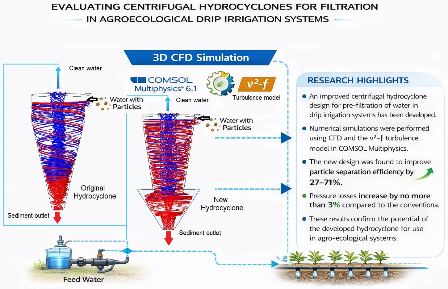
- An improved centrifugal hydrocyclone design for pre-filtration of water in drip irrigation systems has been developed.
- Numerical simulations were performed using CFD and the v²–f turbulence model in COMSOL Multiphysics.
- The new design was found to improve particle separation efficiency by 27–71%.
- Pressure losses increase by no more than 3% compared to the conventional model.
- These results confirm the potential of the developed hydrocyclone for use in agro-ecological systems.
1. Introduction
Water scarcity and the need for efficient resource use have led to the widespread adoption of drip irrigation systems, particularly in arid and semi-arid agro-ecological zones. Drip irrigation delivers water directly to the root zone of plants with minimal evaporation and runoff losses, making it one of the most efficient irrigation methods available. However, drip irrigation efficiency is highly dependent on the quality of the supplied water, as even low concentrations of suspended solids can lead to clogging of drippers, reducing system efficiency and increasing maintenance costs. To address these issues, pre-filtration of irrigation water has become a critical component of system design. Among various filtration technologies, centrifugal hydrocyclones have attracted attention due to their mechanical simplicity, low operating costs, and ability to remove particles without the use of filter media. These devices use centrifugal force to separate solids from the water flow, thereby protecting the sensitive components of drip irrigation systems [1]. Since the mid-20th century, hydrocyclones have been widely used in various industries, including chemical processing, mining, coal preparation, and powder handling. This surge in popularity can be attributed to their simple design, ease of operation, excellent performance, minimal maintenance requirements, and compact size [2].
A typical hydrocyclone has a cylindrical section connected to a central pipe leading to a conical section with an outlet pipe. Liquid enters the hydrocyclone tangentially through an inlet pipe at the top of the cylinder [3]. This tangential flow creates a vortex, generating centrifugal forces within the device. These centrifugal forces effectively separate solid particles from the surrounding liquid [4].
The flow dynamics within a hydrocyclone are complex, so engineers often rely on empirical equations to predict device performance. These empirical equations are developed based on the analysis of large amounts of experimental data and incorporate the effects of hydrocyclone geometric parameters and operating conditions. Variations in experimental data can lead to different equations for the same key parameters [5-8]. Empirical models typically relate a classification parameter, such as particle size, to device dimensions and the properties of multiphase mixtures [9], [10]. However, like all empirical models, they are limited by the experimental data used to derive their parameters. This limitation underscores the appeal of mathematical models based on fluid mechanics. Such models are highly desirable because they offer a broader scope of application, extending beyond the specific limitations of experimental datasets [11-13].
Computational fluid dynamics (CFD) is a versatile tool capable of predicting velocity profiles in a variety of design and operational scenarios. At its core, CFD relies on the numerical solution of the Navier-Stokes equations, which form the foundation of any computational method in fluid dynamics. This approach began to penetrate into hydrocyclone analysis in the early 1980s, facilitated by significant advances in computer technology and a deeper understanding of turbulent flow modeling [14], [15]. These developments allowed for more accurate simulations of fluid behavior inside hydrocyclones, facilitating better performance and efficiency predictions.
In recent years, considerable attention has been paid to the numerical modeling of flows in centrifugal and hydrocyclone devices using modern turbulence models and multiphase approaches. Thus, in works [16-18], two-phase and turbulent flows in centrifugal separators were modeled based on the Navier-Stokes equations, which made it possible to clarify the structure of vortex zones and pressure distribution. In the article [19], the SARC turbulence model was used to describe air centrifugal flows, demonstrating high accuracy in comparison with traditional - models. In later studies, Madaliev et al. [20], [21] considered the problems of numerical analysis of the efficiency of high-performance and three-phase hydrocyclones, which expands the understanding of the processes of separation of solid particles in complex multiphase media. This paper logically continues these studies, focusing on a comparative analysis of a classic and new hydrocyclone design using the turbulence model, adapted for irrigation in agro-ecological systems.
Under practical agro-ecological conditions, the proposed hydrocyclone design demonstrates high adaptability to a variety of drip irrigation system parameters [22-26]. The modular geometry of the device allows for scaling depending on the water flow rate and suspended particle concentration characteristic of various water sources and field conditions. The absence of filter materials reduces the need for maintenance, which is especially important for agricultural regions with limited operational resources. The numerical modeling results presented in this paper provide the basis for subsequent optimization of the hydrocyclone design for specific applications, including varying flow rates and particle distributions. Thus, the new design has the potential for direct application in real-world drip irrigation systems, ensuring improved water quality and the sustainability of the irrigation network. Most previous studies of hydrocyclone performance have focused on industrial scales and are based on empirical relationships. However, the results of such studies have limited applicability to agro-ecological irrigation systems due to differences in hydrodynamic regimes, particle distribution, and operating conditions. Furthermore, the influence of inlet geometry on separation efficiency using modern turbulence models remains insufficiently understood. This study aims to address these limitations through a numerical analysis of a new hydrocyclone design [27-30].
This study proposes a new centrifugal hydrocyclone design tailored to the specific needs of agro-ecological drip irrigation systems. The novelty of this approach lies in the optimization of the housing geometry and flow configuration using numerical simulation (CFD) and the turbulence model, which enabled the first comprehensive analysis of velocity, pressure, and particle trajectory distributions under two-phase flow conditions typical of irrigation systems. This approach provides a more accurate description of solid-liquid separation processes, which has previously been considered only to a limited extent in similar studies.
The primary research method is a comparative analysis of the efficiency of a conventional and modernized hydrocyclone. Using numerical simulations in COMSOL Multiphysics 6.1, quantitative relationships between flow velocity, pressure loss, and particle collection efficiency were obtained. The results showed that the new design provides a 27-71 % increase in separation efficiency, depending on the inlet flow velocity, with a slight (≈ 3 %) increase in hydraulic resistance. This confirms that optimizing the hydrocyclone's internal shape and adjusting its geometric proportions can significantly improve performance without increasing energy costs.
Thus, the scientific novelty of this study lies in the development and numerical verification of an improved centrifugal hydrocyclone design specifically designed for pre-filtration of water in drip irrigation systems. It has been shown for the first time that the use of the turbulent model in combination with Lagrangian particle tracking provides increased accuracy in predicting separation efficiency and allows the substantiation of optimal design parameters of the device for real conditions of agro-ecological systems.
2. Physical and mathematical formulation of the problem
Fig. 1 shows schematic images of a classic centrifugal hydrocyclone and the new hydrocyclone proposed in this work, which allow us to directly assess the design differences and the impact of these differences on the separation efficiency. In Fig. 1(a): 450 mm, 2180 mm, 210 mm, 80 mm, 850 mm, 325 mm, 180 mm and Fig. 1(b): 210 mm, 1600 mm, 1000 mm, 210, 80 mm, 810 mm, 325 mm, 180 mm, 490 mm, 810 mm.
Fig. 1Centrifugal hydrocyclones: a) original hydrocyclone, b) new centrifugal hydrocyclone
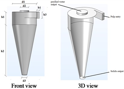
a)
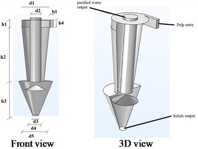
b)
2.1. Boundary conditions
For the numerical simulation, an axisymmetric 3D hydrocyclone model was used, constructed in COMSOL Multiphysics 6.1 using the turbulent model. The following boundary conditions were adopted.
Inlet:
where 𝑉 is the average velocity of the incoming liquid flow, varied parametrically to analyze the effect of the flow regime on separation efficiency. Inlet turbulence was described by the turbulence intensity and turbulence length scale, determined by the empirical relationships , 0.07.
Outlet cross-section:
This condition ensures free flow of liquid at atmospheric pressure.
Walls: For liquids, the no-slip condition applies, and for the model, the following applies:
where 𝑘 is the turbulent kinetic energy. is the condition of absence of normal flux of turbulent kinetic energy through the wall (impermeable smooth wall). is the unit vector normal to the wall. is the rate of dissipation of turbulent kinetic energy. is a model constant of the model, determining the relationship between turbulent viscosity and turbulence parameters. is a damping function taking into account the influence of the wall on the turbulence structure. is a logarithmic limit function providing consistency with the logarithmic velocity law far from the wall. is the distance from the point under consideration to the nearest wall. is the characteristic turbulent length scale (the integral scale of turbulence). is the characteristic length for dissipation, used to determine near the wall. is the transition function, providing a smooth transition from the laminar sublayer to fully developed turbulence. , are empirical constants of the model.
For solid particles, the elastic reflection condition (Bounce condition):
where 𝑛 is the normal to the wall.
Particle motion. Particle trajectories are described by the Lagrangian equation of motion:
here: is the particle mass, is the gravitational acceleration, – resistance force, 𝐶𝐷 – drag coefficient calculated using empirical dependence:
where Properties of particles: 1560 kg/m3, 10-80 μm, which corresponds to the range of mineral silt and sand inclusions typical for irrigation waters.
The selected velocity range (1-8 m/s) encompasses the laminar-turbulent transition modes typical of small- and medium-capacity hydrocyclones used in irrigation water filtration. These velocities ensure stable formation of a vortex flow structure and minimize the risk of wall erosion. The particle size range (10-80 µm) reflects the actual characteristics of mechanical impurities (silt, sand, clay) found in natural waters and agricultural wastewater.
To determine the spatial distribution of velocity, pressure, and turbulence characteristics of the fluid flow in the hydrocyclone, the RANS (Reynolds-Averaged Navier-Stokes) equation system is solved. This equation describes the motion of a viscous incompressible fluid, taking into account the time-averaging of turbulent fluctuations. This system is a modified form of the classical Navier-Stokes equations, in which instantaneous values of velocity and pressure are replaced by their average values, and the influence of velocity fluctuations is taken into account using additional terms – the so-called Reynolds stresses.
Higher-order forces, such as turbulent migration (TDF) and the Magnus effect, were not considered due to their extremely small influence in the range of parameters studied. Indeed, the turbulent migration force is proportional to the gradient of turbulent kinetic energy and becomes significant for large-scale eddies and particles larger than 200 μm [31]. In the present study, the particle diameter is 10-80 μm, and the particle Reynolds number is 10, which corresponds to a laminar or transient regime of relative motion. Under these conditions, the diffusion component has no significant effect on the particle trajectory.
The Magnus effect, which occurs due to the rotation of particles, is described by the force:
where is the Magnus coefficient, is the angular velocity of the particle. For small spherical particles in water flows, the torque induced by the velocity shear quickly decays due to the viscosity of the fluid, and the force turns out to be an order of magnitude smaller than . The calculation showed that for 50 µm and 5 m/s, the ratio < 0.02. Thus, within the considered range of parameters, these effects do not have a significant impact on the particle hydrodynamics and can be reasonably excluded from the model without loss of accuracy. This approach is widely used in similar studies on the numerical modeling of hydrocyclones [25], [32], [33].
In vector form, the RANS equations are written as follows:
where: – vector of time-averaged flow velocity m/s, – average pressure Pa, – liquid density kg/m3, – dynamic viscosity Pa s, is the Reynolds stress tensor arising due to turbulent velocity fluctuations, is the acceleration due to gravity, is the vector of external mass forces (e.g., centrifugal forces).
The Reynolds stress tensor is modeled using the turbulent model, which provides increased accuracy in the presence of near-wall vortex structures characteristic of internal flows in hydrocyclones. According to the Boussinesq hypothesis, this tensor is expressed in terms of turbulent viscosity :
where is the turbulent kinetic energy, and is the unit tensor. Solving this system of equations allows us to determine three-dimensional velocity and pressure fields, identify recirculation zones and intense vortex formations, and quantitatively evaluate the efficiency of solid particle separation under the action of centrifugal and gravitational forces. Thus, using the RANS equations in conjunction with the turbulence model ensures physically correct and numerically stable modeling of complex vortex flows in hydrocyclone devices.
2.2. turbulence model
Near solid walls, turbulent velocity fluctuations are not isotropic: fluctuations along the wall (tangential) have a much higher amplitude than those normal to the wall (perpendicular). This is due to the “no-slip condition” acting on the wall surface, which strongly damps the fluctuations in the normal direction, while allowing the tangential components to develop relatively freely. As one moves away from the wall, the effect of viscosity decreases and the turbulent fluctuations become equal in all directions, gradually approaching an isotropic state. The turbulence model was developed to account for this anisotropic turbulent behavior observed in boundary layers. The model includes a transport equation for the square of the component of the turbulent velocity normal to the wall () and an additional equation () representing the turbulent energy redistribution function. These equations are calculated together with the standard transport equations that solve for the turbulence kinetic energy () and its dissipation ().
In this way, the model allows for a more accurate representation of the spatially varying properties of turbulence in different regions of the flow field, especially near the wall, and more fully describes the real physical mechanisms of the degree of anisotropy.
Turbulent eddy viscosity is calculated using: . The remaining coefficients and functions were presented in article [34]. In modeling the kinematics of particle motion within turbulent two-phase flows, no single representation can fully capture all aspects accurately [35].
3. Calculation grids
To assess the impact of computational grid density on the stability and reliability of numerical results, a grid independence study was conducted. Calculations were performed for five grid levels – from very coarse to fine – with the number of elements varying as follows (Table 1).
Table 1Number of elements across five grid levels
Grid type | Number of elements (Original hydrocyclone) | Number of elements (New hydrocyclone) |
Extra coarse | 32 105 | 55 238 |
Corser | 80 581 | 143 738 |
Corse | 172 922 | 288 663 |
Normal | 448 651 | 708 759 |
Fine | 1 072 457 | 2 308 785 |
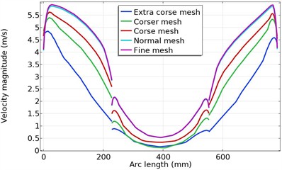
Fig. 2 shows the change in flow velocity modulus along the arc length in a cross-section located 400 mm below the hydrocyclone’s top cover for different mesh types. The graphs show that when switching from a normal mesh to a finer mesh, the velocity modulus values change by no more than 2-3 %, indicating mesh convergence. Thus, further increasing mesh density has virtually no effect on the obtained hydrodynamic characteristics, but significantly increases computational costs.
The convergence criterion for the numerical solution was the relative change in the integral parameters (average pressure and outlet velocity), which did not exceed 1×10⁻3 between successive iterations. The simulation time at the Fine Mesh stage ensured a stable solution without oscillations in the velocity and pressure fields. The analysis revealed that the Normal Mesh provides the optimal balance between computational accuracy and cost, and this mesh was used for subsequent flow parameter calculations and hydrocyclone performance evaluations.
Fig. 2Change in the flow velocity module along the arc length in a section located 400 mm below the top cover of the hydrocyclone
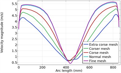
a) Original hydrocyclone
b) New hydrocyclone
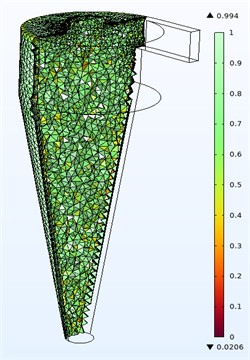
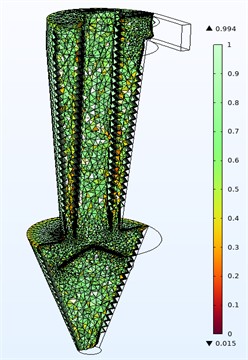
Fig. 3 shows the computational meshes (Normal mesh) for modeling the flow in hydrocyclones.
Fig. 3Computational meshes (Normal mesh) for modeling flows in hydrocyclones
a) Original design
b) New hydrocyclone design
A normal mesh was used for the numerical simulation, providing an optimal balance between accuracy and computational effort. The computational domains were discretized using tetrahedral elements with localized densification near the walls, inlet nozzle, and outlet openings, where maximum velocity and pressure gradients are observed. The average mesh quality was 0.78, ensuring stable convergence of the solution. The total number of elements was 448,651 for the original hydrocyclone and 708,759 for the new design.
4. Solution method
The finite element method (FEM) implemented in COMSOL Multiphysics 6.1 was used to numerically simulate the flow and particle motion in a hydrocyclone. The Navier-Stokes equations were Reynolds-averaged (RANS) using the turbulent model, which provides a highly accurate description of vortex and wall flows. The steady-state form of the RANS equations was solved in the calculations to determine the velocity and pressure distributions of the liquid phase. A standard stationary solver with a second-order implicit scheme was used for the numerical solution. A residual factor of 1×10⁻3 served as the convergence criterion. The calculations were performed until a stable flow field was achieved, at which the change in the integral parameters (velocity and pressure) between iterations did not exceed 0.1 %. The number of iterations required for convergence depended on the mesh type and averaged between 50 and 300 iterations. For each hydrocyclone geometry, five mesh types were considered (from extra coarse to fine mesh), which allowed us to evaluate the effect of discretization on the accuracy of the results and select the optimal Normal mesh. After obtaining a steady-state velocity field for the liquid phase, unsteady-state particle motion simulation was performed using the Particle Tracing for Fluid Flow module. Particles were introduced into the inlet section with initial velocities equal to the velocity of the first (liquid) phase. The particles were subjected to gravity and drag forces, which were described by the -equation of motion. The Bounce condition (elastic reflection without adhesion) was applied to the hydrocyclone walls, and the Freeze condition (fixation of particles upon exiting the calculation domain) was applied to the outlet boundaries. Particle trajectories were calculated over time, and separation efficiency was determined based on an analysis of their exit through the lower and upper nozzles. Thus, the combined use of a steady-state solution for the liquid phase and a non-stationary analysis of particle trajectories made it possible to reliably estimate the velocity distributions, pressures, and separation efficiency in various hydrocyclone designs.
5. Calculation results and their discussion
To assess the reliability and adequacy of the numerical model, the calculation results were compared with experimental data published in [26], which investigated the velocity fields in a 75 mm hydrocyclone. Numerical calculations were performed for similar conditions using two turbulence models: RNG - and . Fig. 4 shows a comparison of the radial distributions of the tangential velocity with the experiment at a height of 60 mm from the top cover of the hydrocyclone.
Fig. 4Comparison of radial distributions of tangential velocity with the experiment at a height of 60 mm from the top cover of the hydrocyclone
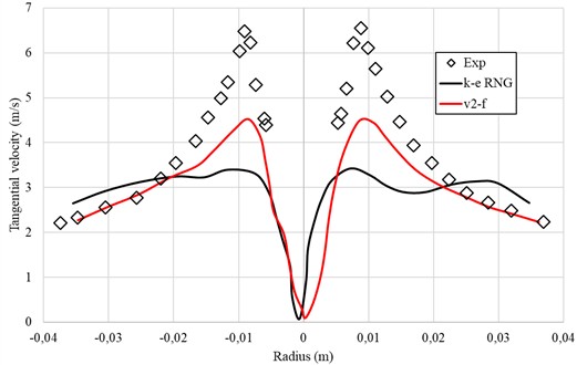
As can be seen from the graph, the model provides the best fit to the experiment in the region of intense vortex flow (0.01-0.02 m), correctly describing the distribution shape and maximum tangential velocity. The RNG - model shows somewhat smoothed values, consistent with its known tendency to underestimate turbulent energy under strong rotational motion. Thus, the validation confirms that the applied numerical approach is capable of reliably reproducing the flow structure inside a hydrocyclone. This allows the model to be used for comparative analysis of different designs without conducting additional physical experiments.
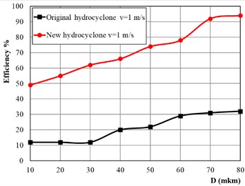
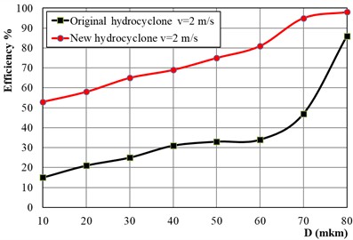
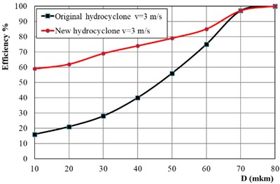
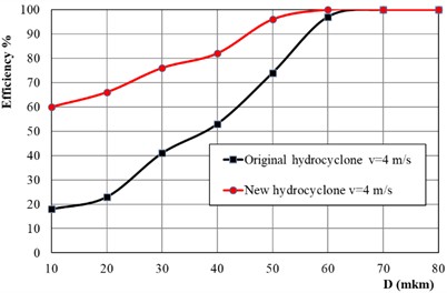
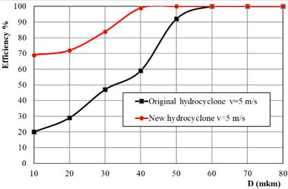
To determine the efficiency of dust collectors in Fig. 5 shows the percentage values of outgoing dust particles of a certain fraction at different inlet speeds.
Fig. 5Efficiency of hydrocyclones in particle capture
a)
b)
c)
d)
e)
Fig. 5 shows the dependence of particle separation efficiency on their diameter at various inlet flow rates for the conventional and proposed hydrocyclones. Analysis of the graphs shows that the new design provides significantly higher particle collection efficiency across the entire velocity range. At a velocity of 1 m/s, the efficiency of the new model is higher by approximately 71 %, at 2 m/s by 53 %, at 3 m/s by 35 %, at 4 m/s by 30 %, and at 5 m/s by 27 % compared to the original design. The increase in efficiency with increasing velocity is explained by increased centrifugal forces, which promote more intensive separation of particles from the liquid. At the same time, the new housing geometry creates a more stable vortex flow field and reduces the likelihood of back-carrying of small particles, which is especially noticeable at low speeds. Consequently, the proposed hydrocyclone demonstrates advantages not only in overall efficiency but also in process energy stability, enabling high-quality filtration at relatively low flow rates. This makes the design particularly promising for use in irrigation water filtration systems and other industrial processes involving finely dispersed impurities.
In Fig. 6 shows the aerodynamic resistance of hydrocyclones.
Fig. 6Resistance of hydrocyclones
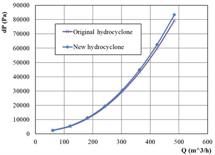
Fig. 6 shows the change in pressure drop () as a function of fluid flow rate (𝑄) for the original and new hydrocyclones. The relationship is quadratic, consistent with the typical behavior of centrifugal devices, where pressure losses increase proportionally to the square of the flow velocity. At all flow rates, the new hydrocyclone exhibits slightly higher hydraulic resistance – on average, 3 % higher than the baseline design. This is explained by the change in the inlet geometry and the shape of the conical section, which create a more intense rotational motion of the fluid. However, a small increase in pressure drop does not significantly affect the overall efficiency of the device, since the increase in centrifugal force compensates for the additional energy losses. The results demonstrate that the modified design provides an optimal balance between separation efficiency and energy costs. Thus, it can be concluded that, in practical application, the new hydrocyclone design does not require a significant increase in pumping equipment capacity and can be implemented in existing irrigation and filtration systems without changing the hydraulic operating mode.
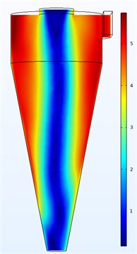
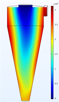
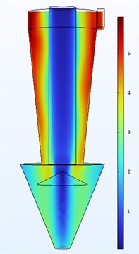
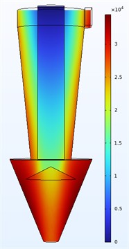
In Fig. 7 shows contour graphs of the average axial velocity and pressure of hydrocyclones in the middle plane.
Fig. 7Isolines of the velocity and pressure fields in hydrocyclones: a), b) original hydrocyclone, c), d) recommended hydrocyclone
a)
b)
c)
d)
Fig. 7 shows the velocity and pressure field distributions for the classic and new hydrocyclones under identical boundary conditions. The velocity isolines demonstrate a typical rotational flow structure, including a central zone of a downward and upward vortex. The original design (a) is characterized by an uneven velocity distribution: high velocity is observed along the housing wall and decreases sharply in the axial zone. This indicates a partial loss of kinetic energy and instability of the internal vortex, which can reduce the efficiency of separating small particles. In the new design (b), the velocity field is characterized by a more uniform distribution. The maximum velocity values are concentrated closer to the periphery, which creates stable circulation and increases the centrifugal forces acting on the particles. This flow structure promotes more efficient movement of solids toward the walls and their subsequent removal through the lower outlet. The pressure distribution shows a typical gradient: from a high value near the wall to a minimum at the center of the vortex. The new design has a slightly higher pressure range – up to 3.4×10⁴ Pa – due to more intense flow rotation. The pressure gradient is smoother, indicating stabilization of the internal vortex and reduced hydrodynamic losses.
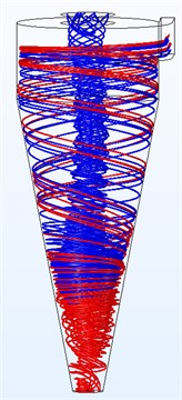
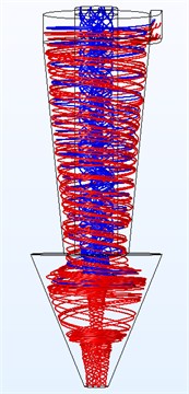
In Fig. 8 shows the current line.
Fig. 8Flow line a) original hydrocyclone, b) recommended hydrocyclone
а)
b)
The original hydrocyclone (a) exhibits pronounced vortex flow asymmetry: the streamlines in the central region have an unstable spiral structure with frequent intersections. This indicates the presence of zones of reverse flow and turbulent dispersion, which can lead to particle re-entrainment and reduced separation efficiency. In the new hydrocyclone design (b), the streamlines are more orderly and uniformly distributed along the device axis. An internal upward flow forms closer to the center, without noticeable recirculation zones, indicating stabilization of the secondary vortex. Furthermore, the inclination angle of the downward spirals indicates increased centrifugal acceleration, which facilitates faster movement of solid particles toward the wall and their removal through the lower outlet. Thus, analysis of the streamline structure shows that the proposed design generates a more stable and symmetrical rotational flow, ensuring effective phase separation while maintaining a stable hydrodynamic regime within the housing.
Table 2 shows the updated data obtained from CFD modeling.
As Table 2 shows, the efficiency of the new design ranges from 71 to 98 %, while for a classic hydrocyclone it ranges from 42 to 77 %. Thus, the difference in efficiency reaches 71 % at low flow rates (1 m/s), when the influence of geometry is most pronounced.
Table 2Updated data obtained from CFD modeling
Flow velocity (m/s) | Efficiency of a classic hydrocyclone (%) | Efficiency of the new hydrocyclone (%) | Efficiency gain (%) |
1 | 41.5 | 71.0 | +71 % |
2 | 57.6 | 88.4 | +53 % |
3 | 68.2 | 92.1 | +35 % |
4 | 73.0 | 95.0 | +30 % |
5 | 76.9 | 97.8 | +27 % |
6. Conclusions
This paper presents a numerical study of the hydrodynamic characteristics of a new type of hydrocyclone designed for use in drip irrigation systems. A comparative analysis revealed that the proposed design provides higher suspended particle separation efficiency with a slight increase in hydraulic resistance compared to the traditional model. Using the turbulence model allowed for a highly accurate description of the internal vortex flow structure and validation of the numerical simulation results. Further developments in this study include experimental verification of the numerical model to quantitatively compare simulation results with laboratory measurements, as well as an analysis of the influence of various parameters (particle diameter, density, and body shape) on separation efficiency. Furthermore, the proposed results can be adapted for the design of filtration devices in related fields, such as water treatment, food processing, and chemical processing, where compact and energy-efficient methods for separating suspended solids are required. Thus, the developed model serves as a reliable tool for optimizing hydrocyclone design and can be used as a basis for further experimental and applied research.
References
-
A. C. Hoffmann, M. de Groot, W. Peng, H. W. A. Dries, and J. Kater, “Advantages and risks in increasing cyclone separator length,” AIChE Journal, Vol. 47, No. 11, pp. 2452–2460, Apr. 2004, https://doi.org/10.1002/aic.690471109
-
R. B. Xiang and K. W. Lee, “Numerical study of flow field in cyclones of different height,” Chemical Engineering and Processing: Process Intensification, Vol. 44, No. 8, pp. 877–883, Aug. 2005, https://doi.org/10.1016/j.cep.2004.09.006
-
Y. Zhu and K. W. Lee, “Experimental study on small cyclones operating at high flowrates,” Journal of Aerosol Science, Vol. 30, No. 10, pp. 1303–1315, Dec. 1999, https://doi.org/10.1016/s0021-8502(99)00024-5
-
A. Avci and I. Karagoz, “Effects of flow and geometrical parameters on the collection efficiency in cyclone separators,” Journal of Aerosol Science, Vol. 34, No. 7, pp. 937–955, Jul. 2003, https://doi.org/10.1016/s0021-8502(03)00054-5
-
T. G. Chuah, J. Gimbun, and T. S. Y. Choong, “A CFD study of the effect of cone dimensions on sampling aerocyclones performance and hydrodynamics,” Powder Technology, Vol. 162, No. 2, pp. 126–132, Mar. 2006, https://doi.org/10.1016/j.powtec.2005.12.010
-
C.-W. Hsu, S.-H. Huang, C.-W. Lin, T.-C. Hsiao, W.-Y. Lin, and C.-C. Chen, “An experimental study on performance improvement of the stairmand cyclone design,” Aerosol and Air Quality Research, Vol. 14, No. 3, pp. 1003–1016, Jan. 2014, https://doi.org/10.4209/aaqr.2013.04.0129
-
J. W. Lee, H. J. Yang, and D. Y. Lee, “Effect of the cylinder shape of a long-coned cyclone on the stable flow-field establishment,” Powder Technology, Vol. 165, No. 1, pp. 30–38, Jun. 2006, https://doi.org/10.1016/j.powtec.2006.03.011
-
A. Surmen, A. Avci, and M. I. Karamangil, “Prediction of the maximum-efficiency cyclone length for a cyclone with a tangential entry,” Powder Technology, Vol. 207, No. 1-3, pp. 1–8, Feb. 2011, https://doi.org/10.1016/j.powtec.2010.10.002
-
V. S. Kuznetsov and V. V. Yarots, “Calculation of parameters for liquid expiration through cylindrical throttle channels in the mode of" blockage effect" existence,” Mashinostroenie i Inzhenernoe Obrazovanie, No. 4, pp. 8–14, 2016.
-
L. A. Tarasova, “Improving the technological efficiency of vortex-type devices in gas cleaning systems,” Moscow State University of Environmental Engineering, 2010.
-
P. E. Smirnov, “Testing of the v^2 – f model of turbulence in calculating the flow and heat transfer in an abruptly expanding duct,” Journal of Engineering Physics and Thermophysics, Vol. 79, No. 4, pp. 666–672, Jul. 2006, https://doi.org/10.1007/s10891-006-0151-9
-
A. S. Timonin, Engineering and Environmental Reference Book T. 1. (in Russian), Kaluga: Publishing House N. Bochkareva, 2003.
-
G. G. Chuyanov, Dewatering and Dust Collection. Yekaterinburg: UGGGA, 2003.
-
V. S. Shvydkiy and M. G. Ladygichev, Gas Purification. Moscow: Teploenergetik, 2002.
-
E. A. Shtokman, Air Purification. Moscow: Association of Construction Universities (ACU), 2007.
-
Z. M. Malikov and M. E. Madaliev, “Numerical simulation of two-phase flow in a centrifugal separator,” Fluid Dynamics, Vol. 55, No. 8, pp. 1012–1028, Jan. 2021, https://doi.org/10.1134/s0015462820080066
-
Z. M. Malikov and M. E. Madaliev, “Mathematical modeling of a turbulent flow in a centrifugal separator,” Vestnik Tomskogo Gosudarstvennogo Universiteta. Matematika I Mekhanika, No. 71, pp. 121–138, Jan. 2021, https://doi.org/10.17223/19988621/71/10
-
M. Madaliev, “Modeling of turbulent two-phase flow based on a two-fluid approach,” Journal of Applied and Computational Mechanics, Vol. 11, pp. 204–222, Jul. 2024, https://doi.org/10.22055/jacm.2024.46940.4632
-
Erkinjon Son and Madaliev Murodil, “Numerical calculation of an air centrifugal separator based on the SARC turbulence model,” Journal of Applied and Computational Mechanics, Vol. 6, pp. 1133–1140, Dec. 2020, https://doi.org/10.22055/jacm.2020.31423.1871
-
M. Madaliev, Z. Abdulkhaev, Y. Khusanov, S. Mirzababayeva, and Z. Abobakirova, “Numerical study of highly efficient centrifugal cyclones,” Acta hydrotechnica, Vol. 37, No. 67, pp. 137–151, Dec. 2024, https://doi.org/10.15292/acta.hydro.2024.08
-
M. Murodil, A. Zokhidjon, A. Aybek, M. Khamidulla, and G. Mushtariybonu, “Numerical study of three-phase liquid-gas-solid flow in single and group hydrocyclones,” Journal of Mechanical Engineering, Vol. 75, No. 1, pp. 103–110, Apr. 2025, https://doi.org/10.2478/scjme-2025-0011
-
T. R. Vakamalla and N. Mangadoddy, “Numerical simulation of industrial hydrocyclones performance: Role of turbulence modelling,” Separation and Purification Technology, Vol. 176, pp. 23–39, Apr. 2017, https://doi.org/10.1016/j.seppur.2016.11.049
-
M. Azimian and H.-J. Bart, “Numerical analysis of hydroabrasion in a hydrocyclone,” Petroleum Science, Vol. 13, No. 2, pp. 304–319, Apr. 2016, https://doi.org/10.1007/s12182-016-0084-7
-
M. Karimi, G. Akdogan, S. M. Bradshaw, and A. Mainza, “Numerical modelling of air core in hydrocyclones,” in 9th International Conference on CFD in the Minerals and Process Industries, pp. 1–6, 2012.
-
K. T. Hsieh and K. Rajamani, “Phenomenological model of the hydrocyclone: Model development and verification for single-phase flow,” International Journal of Mineral Processing, Vol. 22, No. 1-4, pp. 223–237, Apr. 1988, https://doi.org/10.1016/0301-7516(88)90065-8
-
J. A. Delgadillo and R. K. Rajamani, “A comparative study of three turbulence-closure models for the hydrocyclone problem,” International Journal of Mineral Processing, Vol. 77, No. 4, pp. 217–230, Dec. 2005, https://doi.org/10.1016/j.minpro.2005.06.007
-
M. S. Brennan, M. Narasimha, and P. N. Holtham, “Multiphase modelling of hydrocyclones – prediction of cut-size,” Minerals Engineering, Vol. 20, No. 4, pp. 395–406, Apr. 2007, https://doi.org/10.1016/j.mineng.2006.10.010
-
P. Rudolf, “Simulation of multiphase flow in hydrocyclone,” in EPJ Web of Conferences, Vol. 45, p. 01101, Apr. 2013, https://doi.org/10.1051/epjconf/20134501101
-
Y. Zhang, P. Cai, F. Jiang, K. Dong, Y. Jiang, and B. Wang, “Understanding the separation of particles in a hydrocyclone by force analysis,” Powder Technology, Vol. 322, pp. 471–489, Dec. 2017, https://doi.org/10.1016/j.powtec.2017.09.031
-
M. Durango-Cogollo, J. Garcia-Bravo, B. Newell, and A. Gonzalez-Mancera, “CFD Modeling of hydrocyclones-a study of efficiency of hydrodynamic reservoirs,” Fluids, Vol. 5, No. 3, p. 118, Jul. 2020, https://doi.org/10.3390/fluids5030118
-
C. T. Crowe, T. R. Troutt, and J. N. Chung, “Numerical models for two-phase turbulent flows,” Annual Review of Fluid Mechanics, Vol. 28, No. 1, pp. 11–43, Jan. 1996, https://doi.org/10.1146/annurev.fluid.28.1.11
-
H. Zhou, Z. Hu, Q. Zhang, Q. Wang, and X. Lv, “Numerical study on gas-solid flow characteristics of ultra-light particles in a cyclone separator,” Powder Technology, Vol. 344, pp. 784–796, Feb. 2019, https://doi.org/10.1016/j.powtec.2018.12.054
-
M. D. Slack, R. O. Prasad, A. Bakker, and F. Boysan, “Advances in cyclone modelling using unstructured grids,” Chemical Engineering Research and Design, Vol. 78, No. 8, pp. 1098–1104, Nov. 2000, https://doi.org/10.1205/026387600528373
-
K. Hanjalić, M. Popovac, and M. Hadžiabdić, “A robust near-wall elliptic-relaxation eddy-viscosity turbulence model for CFD,” International Journal of Heat and Fluid Flow, Vol. 25, No. 6, pp. 1047–1051, Dec. 2004, https://doi.org/10.1016/j.ijheatfluidflow.2004.07.005
-
M. Popovac and K. Hanjalic, “Compound wall treatment for RANS computation of complex turbulent flows and heat transfer,” Flow, Turbulence and Combustion, Vol. 78, No. 2, pp. 177–202, Jan. 2007, https://doi.org/10.1007/s10494-006-9067-x
About this article

The authors have not disclosed any funding.
The datasets generated during and/or analyzed during the current study are available from the corresponding author on reasonable request.
Zokhidjon Abdulkhaev: developed the research concept, formulated the methodological framework, supervised the experimental and analytical stages of the study, and conducted the final review and approval of the manuscript. Yunusali Khusanov: performed an extensive literature review on centrifugal hydrocyclone technologies, prepared agroecological filtration references, and contributed to data curation and validation of the obtained results. Islomjon Tohirov: designed and calibrated the hydrocyclone model, carried out the experimental investigations, measured operational parameters, and analyzed the efficiency of the filtration process in drip irrigation systems. Madaliyev Erkin: conducted numerical modeling, optimized the flow conditions inside the hydrocyclone, processed simulation outputs, and contributed to the interpretation of hydrodynamic behavior. Rustam Medatov: prepared the original manuscript draft, organized the structure of the paper, ensured the consistency of scientific explanations, and assisted in technical editing and project coordination.
The authors declare that they have no conflict of interest.

