Abstract
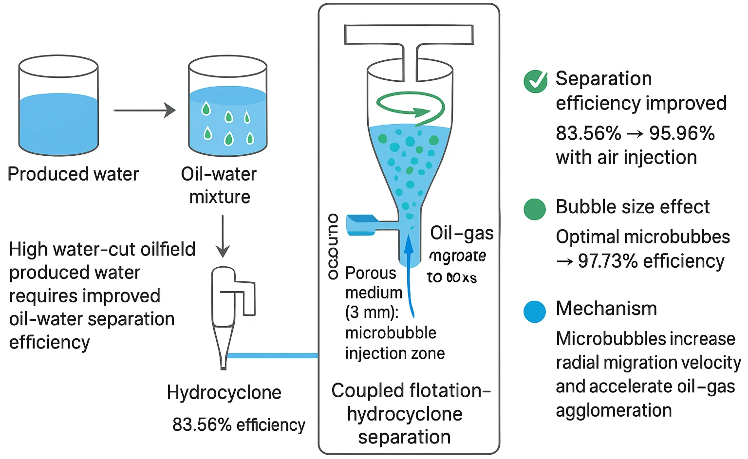
Efficient oil–water separation of produced fluids from high water-cut oilfields requires significant improvement in hydrocyclone separation performance. In this work, computational fluid dynamics simulations were applied to analyze the influence of integrating gas flotation with hydrocyclone separation. To describe the internal flow behavior and the distribution of oil droplets in gas-assisted operation, the Mixture multiphase model together with the Realizable - turbulence model was utilized. Based on a conventional liquid-liquid hydrocyclone, a porous medium region was incorporated into the large cone section to represent microporous walls for microbubble injection, thereby achieving the coupling of flotation and hydrocyclone separation. The results show that gas injection enhanced the separation efficiency from 83.56 % to 95.96 %. Moreover, microbubble size exhibited a pronounced influence on separation performance: smaller bubbles facilitated better oil-water separation. The optimal performance was obtained with an air bubble diameter of 5 μm, where the separation efficiency reached 97.73 %.
Highlights
- A porous-medium microbubble injection zone was integrated into the large cone section of a liquid–liquid hydrocyclone, enabling a coupled gas-flotation and hydrocyclone separation mechanism.
- Air injection significantly enhanced oil–water separation, increasing efficiency from 83.56% to 95.96% by promoting oil–gas agglomeration and accelerating upward migration.
- Microbubble size had a strong impact on performance; smaller bubbles exhibited stronger oil-carrying capacity and promoted faster radial migration of oil droplets.
- The optimal bubble diameter was 5 μm, achieving the highest separation efficiency of 97.73%, demonstrating the importance of precise bubble size control.
- CFD simulations using the Mixture model and Realizable k–ε turbulence closure effectively captured the flow structure and revealed the enhancement mechanism of microbubble-assisted separation.
1. Introduction
With oilfield production moving into a mature stage characterized by high water cut, the water fraction in produced fluids keeps rising, which in turn negatively impacts the operational efficiency and economic performance of oilfield development. Therefore, research on oil-water separation has become particularly important. Hydrocyclone separation technology, a method based on centrifugal forces, was first proposed in 1910 [1]. The development of liquid-liquid hydrocyclone (LLHC) technology was subsequently carried out at Doupont University Laboratory [2], and its fundamental principle is the separation of phases according to density differences.
Young et al. [3] conducted experimental studies on the effects of structural parameters and identified the optimal hydrocyclone design. Bai et al. [4] experimentally optimized operating parameters such as oil droplet distribution and fluid velocity. Al-Kayiem et al. [5] performed numerical simulations on oil–water mixture flow visualization, focusing on the effects of inlet velocity in single- and double-inlet hydrocyclones. Their results indicated that a double-inlet LLHC achieved a separation efficiency of 93.6 % at 1.0 m3/h, which was superior to the 88.5 % efficiency of a single-inlet LLHC. Yang et al. [6] conducted numerical simulations on the separation behavior of oil-water mixtures, emphasizing how droplet size, inlet flow rate, operating pressure, and oil content affect the performance of hydrocyclones. They reported that, under constant oil concentration, separation efficiency was positively correlated with droplet size, inlet pressure, and velocity, achieving efficiencies above 99 %. However, improvements in physical structure and operational parameters alone remain insufficient to fully meet the requirements for high-efficiency hydrocyclone separation.
In recent years, increasing attention has been directed toward integrating gas flotation with hydrocyclone separation. Gas flotation employs bubbles as carriers to adsorb and remove dispersed oil droplets from produced water [7]. Bai et al. [8] experimentally demonstrated that premixing air and liquid using a gas–liquid mixing pump prior to hydrocyclone injection substantially enhanced oil-water separation efficiency, the efficiency rose from 72 % without gas addition to 85 % when the gas-liquid ratio reached 1 %. In related work, Zhao et al. [9] examined hydrocyclones under gas injection conditions and found that the added gas modified the internal flow pattern, which in turn enhanced overall separation efficiency. They also found that the optimal split ratio was 25 %, corresponding to a maximum efficiency of 89.2 %. Nevertheless, the underlying mechanisms of different gas injection strategies and microbubble scales on flow dynamics and separation efficiency remain insufficiently understood and require further systematic investigation.
In this study, computational fluid dynamics (CFD) was applied, where the Mixture multiphase model together with the Realizable - turbulence closure was employed to investigate the flow characteristics inside an oil-water hydrocyclone. A microporous medium region was incorporated into the large cone section of the hydrocyclone to enable microbubble injection. The injected bubbles facilitated the attachment and transport of fine oil droplets by forming oil-gas agglomerates, thereby accelerating the separation process and achieving a coupled flotation-hydrocyclone separation mechanism. Furthermore, the influence of different microbubble diameters on separation efficiency was systematically investigated to provide insights into the optimization of gas-flotation-assisted hydrocyclones.
2. Numerical simulation
2.1. Physical model
Hydrocyclone separators can be designed in various structural forms. In this study, the liquid-liquid hydrocyclone employed is based on the conventional Thew-type double-cone configuration [2], optimized to include two tangential inlets and two conical sections. The upper outlet serves as the overflow, while the lower outlet functions as the underflow. A schematic representation of the hydrocyclone geometry is presented in Fig. 1, and the corresponding geometric parameters are listed in Table 1 [10].
Fig. 1Schematic of the hydrocyclone geometry
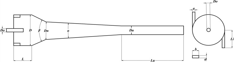
Table 1Geometric parameters of the hydrocyclone (unit: mm)
/ ° | / ° | |||||||||
56 | 14 | 60 | 280 | 50 | 9 | 14 | 6 | 19 | 14 | 3 |
2.2. Mathematical model
This section introduces the fluid dynamics theory underlying the present study, which provides the theoretical basis for the numerical simulations. Considering the wide distribution of oil droplet diameters inside the hydrocyclone, as well as the strong interphase coupling and slip effects, direct application of the Eulerian model would result in high computational cost and complexity. Therefore, in this work, the Mixture model, which offers higher computational efficiency and is well suited for simulating oil-water separation processes, was selected [11].
The governing continuity and momentum equations are expressed as follows [12]:
where represents the density of the mixture, indicates its mass-averaged velocity, denotes the pressure, , are the gravitational and other external body forces, and is the viscous stress tensor.
To capture turbulence effects, the Realizable - closure was applied. Its transport equations can be expressed as follows [12]:
where , , represents the production of turbulence kinetic energy due to velocity gradients, denotes the contribution of buoyancy, is the correction term for compressible fluctuation expansion in the dissipation rate, while and are model constants. and denote the turbulent Prandtl numbers corresponding to the kinetic energy of turbulence and its dissipation rate, respectively.
2.3. Grid and boundary conditions
Within the CFD simulations, the boundary setup at inlet 1 and inlet 2 were defined as velocity inlets, where an oil–water mixture was injected at an inlet velocity of 8 m/s. In this work, both the overflow and underflow exits were defined as pressure outlets. The numerical calculation proceeded for 12,000 steps with a time increment of 0.005. Table 2 provides the fluid-phase parameters applied in the model.
Table 2Fluid parameters
Parameter | Oil phase | Water phase | Air |
Density (kg/m3) | 870 | 998.2 | 1.279 |
Viscosity (Pa·s) | 0.004 | 0.001003 | 1.7894e-05 |
A polyhedral mesh with minimum cell mass of 0.3 was applied to the oil-water hydrocyclone. To accurately simulate air injection through the special microporous section, a porous medium region of 3 mm thickness was introduced in the large cone section, through which air was injected.
To verify grid independence, five different grid sizes (260,000, 640,000, 930,000, 1,440,000, and 2,160,000 elements) were simulated. The results show that with a grid size of 260,000 elements, the separation efficiency is relatively low, as shown in Fig. 2. As the grid size increases, the separation efficiency gradually improves and stabilizes. When the grid size reaches approximately 1.44 million elements, the simulation results no longer exhibit significant variations with further grid refinement. Therefore, a grid size of 1.44 million elements was selected as the base grid for the study.
3. Results and discussion
3.1. Influence of air injection on separation efficiency
The hydrocyclone is used for oil-water separation, where the ratio of the overflow outlet to the inlet flow rate is referred to as the split ratio (m3/s). For the present work, a split ratio of 20 % was specified. The oil-water separation efficiency is defined as [11]:
where the oil concentration at the overflow is denoted as , and corresponds to the inlet concentration.
Fig. 2Grid independence study
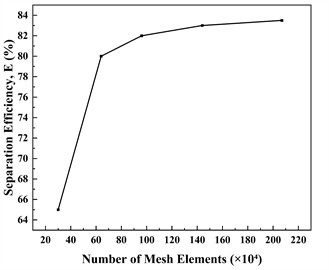
Fig. 3 illustrates the oil volume fraction distribution at the = 0 cross-section of the hydrocyclone. Most of the oil phase after injection is discharged through the overflow outlet, and the oil-water separation efficiency reaches 83.56 %. When 40 μm air bubbles are introduced, the oil droplet volume fraction within the gas-assisted hydrocyclone increases significantly relative to operation without air injection. Microbubbles transport the oil core, and the oil phase volume fraction approaches unity near the overflow port. The majority of the oil phase is discharged via the overflow outlet, leading to an improved separation efficiency of 95.96 % in the hydrocyclone.
In order to better clarify the phase distribution inside the air-assisted hydrocyclone, axial and tangential cross-sections of the large cone section of the hydrocyclone were selected for analysis. The locations of the cross-sections are = 0 mm and = 45 mm, respectively.
Fig. 3(a) shows the oil phase volume fraction distribution at the -section inside the hydrocyclone. The results indicate that oil droplets predominantly gather in the vicinity of the overflow outlet, and the oil core is substituted by a gas core once air is introduced. Due to the carrying effect of microbubbles, the fine oil droplets originally distributed near the wall and difficult to separate can rapidly migrate to the reverse flow core region and flow out through the overflow port. Fig. 3(b) illustrates the oil-phase radial velocity distribution at the -section for cases with and without air injection. It can be observed that under air injection conditions, In the primary operating region of the separator (large cone section), the radial movement speed of oil droplets toward the center is markedly increased, promoting faster droplet coalescence and thereby enhancing oil–water separation efficiency.
3.2. Influence of bubble size on separation efficiency
In order to examine how bubble size influences the separation performance of the oil-water hydrocyclone, five different air bubble diameters were selected for comparison. The results are shown in Table 3. A reduction in bubble diameter leads to a progressive improvement in the hydrocyclone separation efficiency.
When the air injection rate is kept constant, the size of microbubbles markedly affects the radial drift of oil droplets. Analysis shows that the centrifugal force acting on small microbubbles is much smaller than that on large bubbles, allowing them to approach the wall more effectively.
Table 3Numerical results on the separation efficiency of the air-injected hydrocyclone
Bubble size (μm) | 5 | 20 | 40 | 60 | 80 |
Separation efficiency | 97.73 % | 96.52 % | 95.96 % | 95.22 % | 94.79 % |
Fig. 3Oil phase at the section with and without air injection
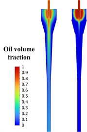
a) Oil volume fraction
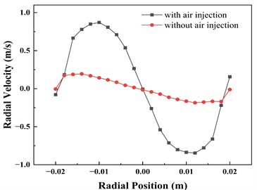
b) Radial velocity distribution of oil phase
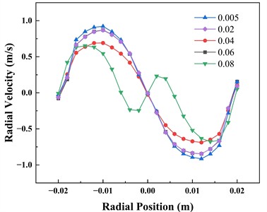
As shown in Fig. 4, when small bubbles are injected, the oil phase exhibits greater radial velocity at the -section, which confirms that smaller microbubbles have a stronger ability to migrate oil droplets. This enables fine oil droplets, originally distributed near the wall and difficult to separate, to rapidly migrate to the reverse flow core region and eventually be discharged from the overflow port, thereby significantly improving the separation efficiency of the hydrocyclone. Under the condition of 5 μm microbubbles, the separation efficiency of the hydrocyclone reaches 97.73 %.
Fig. 4Radial velocity distribution of oil phase under different bubble sizes
4. Conclusions
In this study, computational fluid dynamics (CFD) simulations were performed to system-atically investigate the flow-field characteristics and oil-water separation behavior of a hydrocyclone under gas injection conditions in the cone section. Particular attention was given to the effects of different microbubble diameters on the evolution of the flow structure, interphase interactions, and overall separation performance. The objective of this study was to elucidate the enhancement mechanism of microbubbles in the hydrocyclone separation process, thereby providing theoretical guidance for the structural optimization and engineering application of gas-flotation-assisted hydrocyclone technology. The main conclusions are summarized as follows:
1) A 3 mm-thick porous-medium region was introduced in the large cone section for micro-porous gas injection. The compressed air generated a large number of fine bubbles that rapidly migrated toward the hydrocyclone axis under the combined effects of the swirling flow and buoyancy. These microbubbles adhered to and coalesced with dispersed oil droplets to form oil–gas agglomerates, which significantly enhanced droplet aggregation and upward motion. This process effectively strengthened the centrifugal separation effect, increasing the overall separation efficiency from 83.56 % without gas injection to 95.96 %, thereby verifying the feasibility and superiority of gas-flotation-hydrocyclone coupled separation.
2) The diameter of microbubbles exerted a significant influence on the separation performance. As the bubble size decreased, the specific surface area increased, leading to stronger oil-carrying capacity and a higher probability of oil-bubble attachment. Consequently, oil-phase coalescence and migration were markedly promoted, resulting in a substantial improvement in separation efficiency. When the bubble diameter was 5 μm, the hydrocyclone achieved the best separation performance, with a maximum efficiency of 97.73 %. These findings demonstrate that precise control of the injected bubble size is a key parameter for optimizing the performance of gas-flotation hydrocyclones.
References
-
Y. Liu, Q. Cheng, B. Zhang, and F. Tian, “Three-phase hydrocyclone separator – a review,” Chemical Engineering Research and Design, Vol. 100, pp. 554–560, Aug. 2015, https://doi.org/10.1016/j.cherd.2015.04.026
-
M. Thew, “Hydrocyclone redesign for liquid-liquid separation,” Chemical Engineer, Vol. 427, pp. 17–23, 1986.
-
G. A. B. Young, W. D. Wakley, D. L. Taggart, S. L. Andrews, and J. R. Worrell, “Oil-water separation using hydrocyclones: An experimental search for optimum dimensions,” Journal of Petroleum Science and Engineering, Vol. 11, No. 1, pp. 37–50, Apr. 1994, https://doi.org/10.1016/0920-4105(94)90061-2
-
Z.-S. Bai, H.-L. Wang, and S.-T. Tu, “Experimental study of flow patterns in deoiling hydrocyclone,” Minerals Engineering, Vol. 22, No. 4, pp. 319–323, Mar. 2009, https://doi.org/10.1016/j.mineng.2008.09.003
-
H. H. Al-Kayiem, H. Osei, F. M. Hashim, and J. E. Hamza, “Flow structures and their impact on single and dual inlets hydrocyclone performance for oil-water separation,” Journal of Petroleum Exploration and Production Technology, Vol. 9, No. 4, pp. 2943–2952, May 2019, https://doi.org/10.1007/s13202-019-0690-1
-
M. Yang, R. Jiang, X. Wu, Z. Hu, Y. Yue, and Y. Chen, “Numerical analysis of flow field and separation characteristics in an oilfield sewage separation device,” Advanced Powder Technology, Vol. 32, No. 3, pp. 771–778, Mar. 2021, https://doi.org/10.1016/j.apt.2021.01.026
-
K. T. Amakiri, A. R. Canon, M. Molinari, and A. Angelis-Dimakis, “Review of oilfield produced water treatment technologies,” Chemosphere, Vol. 298, p. 134064, Jul. 2022, https://doi.org/10.1016/j.chemosphere.2022.134064
-
Z.-S. Bai, H.-L. Wang, and S.-T. Tu, “Oil-water separation using hydrocyclones enhanced by air bubbles,” Chemical Engineering Research and Design, Vol. 89, No. 1, pp. 55–59, Jan. 2011, https://doi.org/10.1016/j.cherd.2010.04.012
-
L. Zhao, M. Jiang, and F. Li, “Experimental study on the separation performance of air-injected de-oil hydrocyclones,” Chemical Engineering Research and Design, Vol. 88, No. 5-6, pp. 772–778, May 2010, https://doi.org/10.1016/j.cherd.2009.11.006
-
S. Noroozi, S. H. Hashemabadi, and A. J. Chamkha, “Numerical analysis of drops coalescence and breakage effects on de-oiling hydrocyclone performance,” Separation Science and Technology, Vol. 48, No. 7, pp. 991–1002, Mar. 2013, https://doi.org/10.1080/01496395.2012.752750
-
M. Lu, L. Zhao, Z. Peng, S. Zhang, and M. Jiang, “Research progress on the influence of structural and operating parameters on the enhanced separation performance of mini-hydrocyclones,” Chemical Engineering Research and Design, Vol. 208, pp. 81–93, Aug. 2024, https://doi.org/10.1016/j.cherd.2024.06.045
-
F. A. Morrison, An Introduction to Fluid Mechanics. Cambridge, United Kingdom: Cambridge University Press, 2013.
About this article

The authors have not disclosed any funding.
The datasets generated during and/or analyzed during the current study are available from the corresponding author on reasonable request.
The authors declare that they have no conflict of interest.
