Abstract
Mechanical devices with eccentric shaft synchronization are extensively employed in engineering applications, such as exploration, pile driving, rock breaking, and material selection. In this work, a dynamic model of two eccentric shafts was established to study their synchronization characteristics in a parallel hydraulic motor system. The flow characteristics of two parallel hydraulic motors were considered for nonidentical parameters of the shafts. Our simulation results show that two eccentric shafts can sequentially reach a steady state despite their different parameters. However, their rotational velocities are unequal in the steady state. Further, the viscous damping coefficient more severely influences the synchronization characteristics of the shafts than mass and eccentricity. Finally, we show that the numerical and simulation results are supported by the experimental findings.
1. Introduction
The application of construction machinery enhances labor efficiency while greatly improving working conditions. The working principle of construction machinery involves the synchronization of eccentric shafts, such as sonic drilling rigs [1-3], pile drivers [4], [5], and vibrating screens [6], [7]. Eccentric shaft synchronization in these machines usually relies on lifespan, efficiency, and noise. Therefore, analyzing the synchronization characteristics of eccentric shafts is of great significance.
The investigation of synchronization originated from Huygens' observation of pendulum [8]. Based on extensive studies conducted in the field, the implementation of synchronization is mainly divided into self-synchronization and control synchronization (or forced synchronization) [9], [10]. Self-synchronization refers to the state of synchronization resulting from the natural properties of a process itself and its natural interactions. On the contrary, the realization of control synchronization requires the introduction of special operations or the imposition of special constraints [9]. In self-synchronization research, the theory of the synchronization of two eccentric oscillators was first proposed by Blekhman [11]. The theory was extended by Wen and applied to engineering [12], [13]. Consequently, the zero-valued solution of the coupling equation and stability criterion of oscillators self-synchronization, proposed by Zhao, have been widely discussed [14-16]. Zhang investigated the possibility of the self-synchronization of two to four oscillators with the same [17], [18] or opposite rotating direction [19]. Moreover, he analyzed the stability of synchronization in these structures [20], [21]. These studies focused on synchronization with electric motors as the driving devices. Zhang conducted a pioneering study in the field of self-synchronization driven by hydraulic motors, establishing a synchronization theory and a stability criterion for dual-rotor systems [22]. This work was extended to four-rotor systems by He, and a coefficient of synchronization ability was proposed in his research [5]. Luo revealed the influences of microscopic discrepancies on synchronization performance [23]. These discrepancies include internal leakage, kinematic pair clearances, and resistance coefficients. A synchronization index criterion was established for eccentric rotary systems. Wang introduced a phenomenon called vibratory synchronization transmission in a pile driver and revealed the influences of structural parameters on synchronization stability [24].
Regarding control synchronization or forced synchronization, Shu [25] considered the nonlinear factors of gear structure and analyzed the speed and phase synchronization characteristics of oscillators. Wei reported the torque and speed synchronization characteristics of motors under the gear structure [26]. Kong designed the synchronization controller according to the adaptive sliding mode control algorithm. Based on the controller, the phase and speed synchronization characteristics of multiple rotors in the same direction [27] and composite rotation [28], [29] were studied, and the results were experimentally verified. However, the driving devices involved in these studies were also electric motors. In the context of controlled synchronization or forced synchronization with hydraulic motors serving as the driving units, Li established a dynamic model of a solid-liquid coupling system [30]. Based on a structure combining hydraulic motors with a gear pair, the system stability and high-precision synchronization of two oscillators were validated using various parameters. Moreover, Li designed a novel hydraulic coupling system [31] and analyzed the synchronization of rotational speed and phase for eccentric rotors with unequal parameters. Hu demonstrated high-precision speed control of a valve-controlled hydraulic motor under load fluctuations by introducing a fuzzy adaptive Proportional-Integral-Derivative (PID) algorithm [32]. Du enhanced the synchronization accuracy of a load-sensitive system through variable pressure margin compensation combined with a divertor valve structure [33].
In summary, self-synchronization research mainly focused on obtaining the conditions for realizing synchronization and the criteria for maintaining stability. Meanwhile, the design of synchronization controllers and transmission structures dominated control synchronization or forced synchronization studies. Based on the controllers and transmission structures, the stability of the system and the synchronization characteristics of rotors have been discussed. However, although load parameters in a hydraulic system can influence fluid characteristics, which, in turn, affect the dynamic behavior of the driven structures, few scholars paid attention to the synchronization characteristics of rotating units only in a parallel-drive system.
In address this research gap, we studied the synchronization characteristics of two eccentric shafts driven separately by two hydraulic motors in parallel and investigated the rotational speed synchronization of the shafts with unequal masses, eccentricity, and damping. This article is organized as follows: In Section 2, the motion equation of two eccentric shafts in a parallel hydraulic motor system (PHMS) is derived, and the flow characteristics of the two hydraulic motors are reflected in the motion equation. The comparison of the theoretical, simulation, and experimental findings is reported in Section 3. Finally, the conclusions are presented in Section 4.
2. Modeling
In practical hydraulic systems, pressure losses may occur when pipelines are long or multiple diameter-changing fittings are present. These pressure losses reduce the output torque of the hydraulic motor. For hydraulic motors, external leakage exists at the connections between the housing and end covers. This leakage intensifies with increasing working pressure, thereby reducing the effective flow rate and further decreasing the output torque [34]. For an eccentric rotary system with a deformable support, the rotation of the rotor may cause a shift in the rotational center. This shift induces an additional centrifugal force, leading to a whirling phenomenon and potential system instability [35]. Considering that the hydraulic system under investigation had a pipeline length of less than 2 m, an operating pressure below 16 MPa, and a support stiffness of 2×10⁸ N/m, we assumed that (i) only internal leakage existed in hydraulic motors, and there was no external leakage; (ii) no pressure loss occurred along the pipeline; and (iii) no deformation occurred in supporting structures. Based on these assumptions, the eccentric shafts and hydraulic motors in the PHMS were modeled as a four-rotational-inertia system, as shown in Fig. 1. This model contributes to expound the motion of two eccentric shafts in the PHMS.
Fig. 1Schematic of the motion model of two eccentric shafts in the PHMS
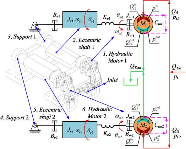
The eccentric shaft is modeled as a moment of inertia , and the viscous damping coefficient during rotation is . The stiffness coefficient of the torsion spring between the eccentric shaft and hydraulic motor is . According to the principle of dynamics, the motion equation of the eccentric shafts is described by:
where and are the mass and eccentricity of the eccentric shaft , respectively; denotes the gravitational acceleration; denotes the angle of the eccentric shaft ; and is the angle of the hydraulic motor .
Eq. (1) indicates that the operation of two eccentric shafts is influenced by the hydraulic motor connected to them. The hydraulic motor connected to the eccentric shafts is modeled as , and the viscous damping coefficient during rotation is . The resulting equations of motion for the two hydraulic motors are described by:
Because is the radial displacement of the hydraulic motor and is a fixed value, we next obtain the load pressure .
The total inlet flow of the system is , and the liquid pressure before diverting is . The total outlet flow is , and the liquid pressure is zero. After diversion, two circuits are formed, where , and 0. Furthermore, it can be calculated: .
When internal leakage is considered, the relationship between the inlet and outlet flow of the two hydraulic motors is expressed as follows:
where, and represent the inlet and outlet flow of the hydraulic motor , respectively; denotes the inlet pressure; and denotes the leakage coefficient.
According to Eq. (3), the load flow of the hydraulic motor is described by:
Provided that the two hydraulic motors are in parallel, the flow of two inlets inevitably fluctuates around an average value. Consequently, the inlet flow can be expressed by a Fourier series [36]:
Eq. (6) can be obtained by substituting Eqs. (2-5) into Eq. (1):
Some transforms are defined as follows:
To solve Eq. (6), is employed to signify the rotational velocity of the eccentric shaft . and can be described as follows: , , , . Finally, we obtain the following equations:
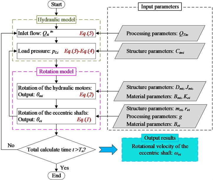
So far, the derivation of the model has been completed. According to the hydraulic model and rotation model, the flowchart of the rotational velocity of the eccentric shafts is shown in Fig. 2.
Fig. 2Flowchart of the proposed analytical model
When investigating synchronization, the choice of the synchronization indicatrix depends on the essence of the mathematical, physical or engineering problem. In this work, the synchronization characteristics of the rotational velocities of two eccentric shafts are discussed considering the requirements of construction machinery and measurement convenience. Notably, specific parameters must not violate the following conditions when elaborating synchronization [37]:
where, and represent two temporal functions possessing identical significance. Both and can quantitatively characterize the relationship between the rotational velocities of the eccentric shafts. When and converge, the rotational velocities of the eccentric shafts are synchronized, and the system is stable. However, they are acceptable for construction machinery (e.g., sonic drill rigs or pile drivers) only when and are small or zero. When and diverge, the system is considered unstable. The first equation elucidates the deviation between and , whereas the second equation provides the deviation rates of and . In the following sections, the first equation is employed to evaluate the synchronization characteristics of the two eccentric shafts, and the second equation is used to assess the deviation between the theoretical data and simulation results.
3. Results and discussion
The motion model of two eccentric shafts in the PHMS is derived in this section. Theoretical calculations, simulation analysis, and experimental research were employed to investigate and analyze the synchronization characteristics of the rotational velocities of the two eccentric shafts. Considering that processing and installation errors are inevitable, we established the parameters under investigation as the mass of the eccentric shaft, ; the eccentricity, ; and the viscous damping coefficient, . The technical parameters of the proposed system are presented in Table 1. The variation of parameters is described as the gain.
Table 1Technical parameters of the proposed system
Parameter | Value | Unit |
1×10⁻⁴ | m3/s | |
8×10⁻⁷ | m3/rad | |
8.5×10⁻¹² | m5/N∙s | |
1.6×10⁻⁴ | kg·m2 | |
1.6×10⁻² | N·m/(rad/s) | |
1.8×10⁻³ | N·m/(rad/s) | |
2.74 | kg | |
0.023 | m | |
2×10⁷ | N/m | |
9.8 | m/s2 |
First, the differential equations in Eq. (7) were solved based on the fourth-order Runge-Kutta relation in MATLAB. Subsequently, simulation analysis was conducted based on the AMESIM platform. Because of the absence of a preselected hydraulic motor model within the AMESIM platform, we developed a super-component that could adequately represent the functionality of the hydraulic motor. The super-component created on the AMESIM platform (shown in Fig. 3) is based on the Parker F11‑5‑MB axial piston motor, which mainly includes the swash plate, plunger pair, and valve plate. The swash plate structure is represented by the SWASH_PISTON_MECH705 component from the AMESIM library. Parameters fi1 through fi5 are used to set the swash plate angles, with 0° and through increasing by 72° sequentially. The plunger is simulated using a piston element and a hydraulic chamber. Five plungers are configured, with a radial clearance of 0.015 mm and a relative eccentricity of 0.5 between the plunger and the cylinder block. The plunger diameter is 11.46 mm. The maximum displacement of the plunger is 9.7 mm, and the maximum velocity is 1.2 m/s. The radius of the plunger pitch circle is 28 mm, and the oil film thickness of the slipper pair is 0.02 mm. In the valve plate module, kidney slots and triangular damping grooves are arranged according to the typical structure of a five‑plunger axial piston motor. The throttle diameter of the valve plate is 8 mm, and the flow area varies piecewise with the cylinder block angle. The maximum operating pressure of the model is 42 MPa, and the maximum rotational speed is 12000 rpm. The displacement per radian, moment of inertia, and viscous damping are consistent with the parameters listed in Table 1. In addition, the dynamic viscosity of the hydraulic oil is set to 0.028 Pa·s, and the bulk elastic modulus is 700 MPa. A variable‑step solver is used for the simulation, with a relative accuracy of 1×10⁻⁶ and an absolute accuracy of 1×10⁻⁹. The total simulation time is 10 s, and the sampling step is 0.001 s.
Fig. 3Simulation schematic on the AMESIM platform: 1. Electromotor; 2. Hydraulic pump; 3. Relief valve; 4. Sequential valve; 5. Hydraulic motor 1; 6. Hydraulic motor 2; 7. Eccentric shaft 1; 8. Eccentric shaft 2; 9. Internal structure of hydraulic motors

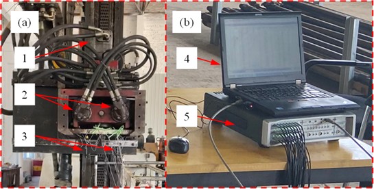
The experimental platform for testing the synchronization of two hydraulic motors in the PHMS is shown in Fig. 4. It mainly includes (a) the tested system and (b) the collection system. The rotational velocity sensor (model DH5604) had a measurement range of 100-20000 rpm, and data acquisition was conducted using Simcenter Scadas Moblie205.
Fig. 4Experimental platform: 1. Dividing valve; 2. Hydraulic motor; 3. Rotational velocity sensor; 4. Computer; 5. Data acquisition. The photos were taken by Jiong Li at a vibration laboratory in Hebei Province on April 21, 2024
3.1. Comparison of theoretical calculation and simulation analysis
3.1.1. Effects of mass on synchronization
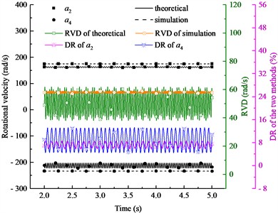
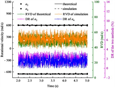
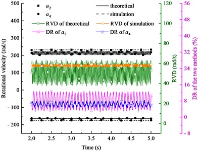
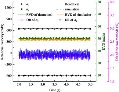
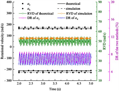
The rotational velocities of two eccentric shafts with nonidentical masses are shown in Fig. 5. Importantly, the positive and negative signs of rotational velocity indicate the difference in direction. Four conditions are described in Fig. 5: (ⅰ) 3×10⁻⁴ m3/s, 2 kg; (ⅱ) 1×10⁻³ m3/s, 2 kg; (ⅲ) 3×10⁻⁴ m3/s, 4 kg; and (ⅳ) 1×10⁻³ m3/s, 4 kg. For each condition, the rotational velocity deviation (RVD) of two eccentric shafts and the deviation rate (DR) of two research methods are analyzed.
Fig. 5Rotational velocity results of two eccentric shafts with nonidentical masses
a) Gain of 3, 2 kg
b) Gain of 10, 2 kg
c) Gain of 3, 4 kg
d) Gain of 10, 4 kg
According to Fig. 5, the rotational velocities of two eccentric shafts can reach a steady state, but their deviation fluctuates around a nonzero value. In Fig. 5(a), the theoretical calculations display that the rotational velocity of eccentric shaft 1 is 162.5 rad/s, and the rotational velocity of eccentric shaft 2 is –212.5 rad/s. The RVD of the two eccentric shafts is 50 rad/s. In addition, in Fig. 5(a), the simulation analysis indicates that the rotational velocity of eccentric shaft 1 is 175.1 rad/s, and the rotational velocity of eccentric shaft 2 is –233.2 rad/s. The RVD of the two eccentric shafts is 58.1 rad/s. For eccentric shaft 1, the DR between the theoretical calculation and simulation analysis is 7.2 %. For eccentric shaft 2, the DR between the two methods is 8.9 %. In Fig. 5(b), the theoretical and simulation results for eccentric shaft 1 are 605.4 rad/s and 594 rad/s, respectively, with a DR of 1.9 %. The theoretical and simulation results for eccentric shaft 2 are –654.9 rad/s and –645.4 rad/s, respectively, with a DR of 1.5 %. Moreover, in Fig. 5(c), the theoretical rotational velocities are 213.8 rad/s and –163.2 rad/s, and the RVD is 50.6 rad/s. The simulated rotational velocities are 232.1 rad/s and –174.3 rad/s, and the RVD is 57.8 rad/s. The RVD rates of the two eccentric shafts under the two approaches are 7.9 % and 6.3 %, respectively. In Fig. 5(d), according to the theoretical calculations, the rotational velocities of the two eccentric shafts are 650 rad/s and –600 rad/s, and the RVD of the two eccentric shafts is 50 rad/s. According to the simulation analysis, the rotational velocities of the two eccentric shafts are 637.4 rad/s and −588.1 rad/s, respectively. The RVD of the two eccentric shafts is 49.3 rad/s. For eccentric shaft 1, the DR between the theoretical calculation and simulation analysis is 1.9 %. For eccentric shaft 2, the DR between the two methods is 2.0 %. The results indicate that the eccentric shaft with a smaller mass attains a higher final rotational velocity in the PHMS.
3.1.2. Effects of eccentricity on synchronization
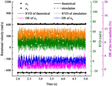
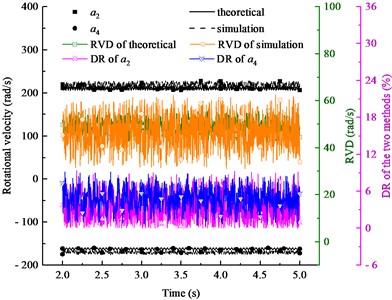
Four conditions are shown in Fig. 6: (ⅰ) 3×10⁻⁴ m3/s, 2×10⁻² m; (ⅱ) 1×10⁻³ m3/s, 2×10⁻² m; (ⅲ) 3×10⁻⁴ m3/s, 4×10⁻² m; and (ⅳ) 1×10⁻³ m3/s, 4×10⁻² m. Similarly, the rotational velocities of the two eccentric shafts can be stabilized independently, with the stabilized values differing from each other.
Fig. 6Rotational velocity results of two eccentric shafts with nonidentical eccentricity
a) Gain of 3, 2×10⁻² m
b) Gain of 10, 2×10⁻² m
c) Gain of 3, 4×10⁻² m
d) Gain of 10, 4×10⁻² m
In Fig. 6(a), the theoretical calculations show that the rotational velocity of eccentric shaft 1 is approximately 162 rad/s, and the rotational velocity of eccentric shaft 2 is –212 rad/s. The RVD of the two eccentric shafts is 60 rad/s. The simulation analysis demonstrates that the rotational velocity of eccentric shaft 1 is approximately 175 rad/s, and the rotational velocity of eccentric shaft 2 is approximately –228 rad/s. The RVD of the two eccentric shafts is 53 rad/s. For the two eccentric shafts, the DR between the two methods is 7.4 % and 7.0 %, respectively. In Fig. 6(b), the theoretical and simulated rotational velocities of eccentric shaft 1 are 614.9 rad/s and 618.7 rad/s, respectively. The corresponding values for eccentric shaft 2 are –655.8 rad/s and –673.2 rad/s, respectively. The DR of the two eccentric shafts are respectively 1.5 % and 2.6 %. In Fig. 6(c), the theoretical rotational velocities are 210.6 rad/s and –161.7 rad/s, and the simulated rotational velocities are 216.5 rad/s and –169.9 rad/s, respectively. The RVD values are 48.9 rad/s and 46.6 rad/s, respectively. In Fig. 6(d), the theoretical calculations indicate that the rotational velocities of the two eccentric shafts are 650 rad/s and 600 rad/s, respectively. The RVD of the two eccentric shafts is 50 rad/s. Furthermore, the simulation analysis demonstrates that the rotational velocity of eccentric shaft 1 is 668.2 rad/s, and the rotational velocity of eccentric shaft 2 is 600 rad/s. The RVD of the two eccentric shafts is 68 rad/s. According to the results shown in Fig. 6(d), for eccentric shaft 1, the DR between the theoretical calculation and simulation analysis is 2.7 %. For eccentric shaft 2, the DR between the two methods is virtually zero. When , the rotational velocity of eccentric shaft 1 is less than that of eccentric shaft 2, whereas it is greater than that of eccentric shaft 2 when .
3.1.3. Effects of the viscous damping coefficients on synchronization
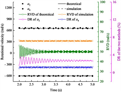
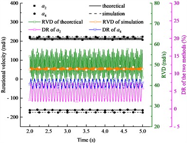
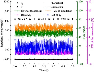
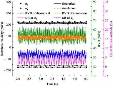
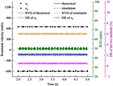
The conditions presented in Fig. 7 include (ⅰ) 3×10⁻⁴ m3/s, 2×10⁻² N·m/(rad/s); (ⅱ) 1×10⁻³ m3/s, 2×10⁻² N·m/(rad/s); (ⅲ) 3×10⁻⁴ m3/s, 4×10⁻² N·m/(rad/s); and (ⅳ) 1×10⁻³ m3/s, 4×10⁻² N·m/(rad/s).
Fig. 7Rotational velocity results of two eccentric shafts with nonidentical viscous damping coefficients
a) Gain of 3, 2×10⁻² N·m/(rad/s)
b) Gain of 10, 2×10⁻² N·m/(rad/s)
c) Gain of 3, 4×10⁻² N·m/(rad/s)
d) Gain of 10, 4×10⁻² N·m/(rad/s)
In Fig. 7(a), the theoretical calculations illustrate that the average rotational velocities of the two eccentric shafts are 212.5 rad/s and –162.5 rad/s, respectively. The RVD of the two eccentric shafts is 50 rad/s. Simulation results show that the average rotational velocities of the two eccentric shafts are 223.2 rad/s and –175.2 rad/s, respectively. The RVD of the two eccentric shafts is 48 rad/s. For eccentric shaft 1, the DR between the theoretical and simulation results is 4.8 %. For eccentric shaft 2, the DR is 7.2 %. In Fig. 7(b), under the two approaches, the rotational velocities of eccentric shaft 1 are 655.9 rad/s and 656.4 rad/s, and the DR is 0.5 %, while the rotational velocities of eccentric shaft 2 are –605.1 rad/s and –595.4 rad/s, respectively, and the DR is 1.6 %. Fig. 7(c) shows that the theoretical results for eccentric shafts 1 and 2 are 214.4 rad/s and –161.1 rad/s, and the simulation results are 224.1 rad/s and –172.6 rad/s, respectively. Under the two approaches, the RVDs of the two eccentric shafts are 53.4 rad/s and 51.5 rad/s, respectively. Moreover, the DR between the theoretical and simulation results are 4.3 % and 6.7 %, respectively. In Fig. 7(d), the theoretical calculations indicate that the rotational velocity of eccentric shaft 1 is 650 rad/s, and the rotational velocity of eccentric shaft 2 is –600 rad/s. The RVD of the two eccentric shafts is 50 rad/s. The simulation results imply that the rotational velocity of eccentric shaft 1 is 650 rad/s, and the rotational velocity of eccentric shaft 2 is –587.4 rad/s. The RVD of the two eccentric shafts is 62.6 rad/s. For the two eccentric shafts, the DR between the theoretical and simulation results are nearly 0 and 2.1 %, respectively. Because in both conditions, the rotational velocity of eccentric shaft 1 is always greater than that of eccentric shaft 2.
3.2. Sensitivity analysis of key parameters
To quantify the influence of individual parameters on the rotational velocity synchronization characteristics, a sensitivity analysis is conducted for the mass, eccentricity, and viscous damping coefficient, as shown in Fig. 8. In Fig. 8, the horizontal axis represents the parameter variation gradient, and the vertical axis represents the variation gradient of the root-mean-square (RMS) of the RVD of the eccentric shafts.
Fig. 8Schematic of the sensitivity analysis
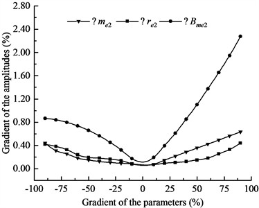
Fig. 8 shows that, overall, the closer the three parameters of eccentric shaft 2 are to Table 1, the smaller the RMS of RVD gradient. The farther they deviate from Table 1, the larger the RVD gradient becomes. Specifically, for mass and eccentricity within [–90 %, –10 %], their effects on the RVD gradient are very similar. Even at a 90 % variation, the RVD gradient changes by only 0.41 %. For viscous damping at 90 % variation, the RVD gradient already changes by 0.83 %. With further parameter increase, the damping effect on the RVD gradient becomes even more significant. This indicates that system stability is more sensitive to viscous damping. Therefore, we will explore system stability under larger parameter variations. This provides a theoretical basis for practical engineering applications.
3.3. Synchronization under large parameter variations
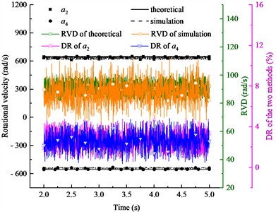
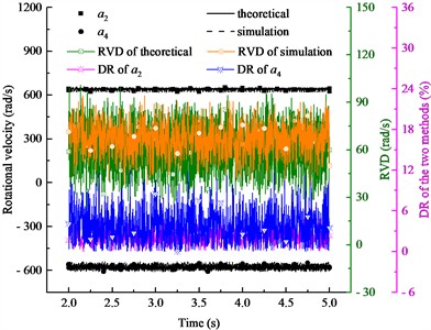
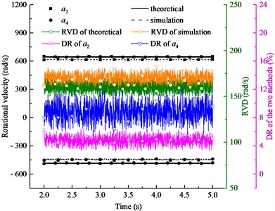
To further examine the robustness of the proposed model, three large-parameter conditions (far beyond typical manufacturing tolerances) are selected to analyze the rotational characteristics of the two eccentric shafts. These three conditions are: (ⅰ) 1×10⁻³ m3/s, 10 kg; (ⅱ) 1×10⁻³ m3/s, 0.1 m (ⅲ) 1×10⁻³ m3/s, 0.1 N·m/(rad/s).
Fig. 9 shows the synchronization characteristics of the two eccentric shafts under three large-parameter conditions. Figs. 9 indicate that both shafts maintain stable rotational velocities. This demonstrates that the proposed model remains robust within the studied parameter range. However, the rotational velocity deviations are 90 rad/s in Fig. 9(a) and 80 rad/s in Fig. 9(b). In Fig. 9(c), the deviation reaches 175 rad/s. This suggests that the load torque approaches the hydraulic motor’s maximum output when parameter differences become large. In practice, the system may stall, and the relief valve would activate. Such conditions fall outside the applicable boundary of the current model.
Fig. 9Rotational velocity results of two eccentric shafts with nonidentical viscous damping coefficients
a) Gain of 10, 10 kg
b) Gain of 10, 0.1 m
c) Gain of 3, 0.1 N·m/(rad/s)
3.4. Mechanistic analysis of the effects of parameters on synchronization
As shown in Figs. 5-7, under the same flow rate, when the parameters of eccentric shaft 2 (the subject of the study) are larger than those of eccentric shaft 1, the rotational velocity of eccentric shaft 2 is always lower than that of eccentric shaft 1. Conversely, when the parameters of eccentric shaft 2 are smaller than those of eccentric shaft 1, the rotational velocity of eccentric shaft 2 is always higher than that of eccentric shaft 1. The reason is that no forced coupling structure exists between the two eccentric shafts, indicating that the loads driven by the two hydraulic motors are different. According to Bernoulli’s equation and the law of conservation of total energy, hydraulic oil tends to flow toward regions with lower resistance, smaller pressure drops, and less energy loss. In such a PHMS, more hydraulic oil flows to the motor driving the smaller load. Consequently, this motor achieves a higher rotational velocity, and the eccentric shaft connected to it rotates faster.
However, among the three analyzed parameters, the viscous damping coefficient has the most significant effect on the synchronization characteristics of the two eccentric shafts. This is because mass influences the load only by changing the equivalent moment of inertia, whereas eccentricity affects the load driven by the hydraulic motor through variations in centrifugal excitation and reaction torque. In contrast, viscous damping directly controls energy dissipation and the dynamic convergence process, exerting a more pronounced influence on synchronization characteristics.
Further, the results show that deviations always exist between the theoretical and simulation results of the two eccentric shafts, mainly caused by two factors: (i) discrepancies between the assumptions used in the theoretical calculations and simulation analyses and (ii) different solution methods used in the two approaches. However, the deviations between the theoretical data and simulation results do not exceed 10 % in any case, indicating the reliability of the results.
3.5. Comparison of theoretical calculation and experimental research
In Section 3.1, the comparison of the theoretical calculations and simulation analysis is displayed. The comparison of the theoretical calculations and experimental findings is analyzed in this section.
For experimental research, adequate preparation, condition configuration, and data collection and analysis are necessary. In the preparation stage, the normal operation of the hydraulic, control, and rotary systems was mainly tested. The rotational velocity sensor converts reflected light signals into electrical pulses. Consequently, rotational velocities are calculated from the pulse frequency. Therefore, the sensor sensitivity was tested during preparation. Two operating conditions were included in this experiment: 3×10⁻⁴m3/s and 1×10⁻³m3/s. For each condition, three parallel tests were conducted, and each test was repeated five times. Considering that the maximum working frequency under the two conditions was approximately 96 Hz, the sampling frequency was set to 500 Hz on the "acquisition setup" interface to prevent information loss. After outlier data were eliminated using the Grubbs criterion, the average value of the three parallel tests was taken as the final experimental result.
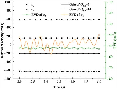
The experimental results obtained from 3×10⁻⁴ m3/s and 1×10⁻³ m3/s are shown in Fig. 10. In this context, the root mean square values of the experimental data and theoretical results were compared. As shown in Fig. 10(a), when 3×10⁻⁴ m3/s, the rotational velocities of eccentric shafts 1 and 2 were 176 rad/s and –200 rad/s, respectively. When 1×10⁻³ m3/s, the rotational velocity of eccentric shaft 1 is 598 rad/s, and the rotational velocity of eccentric shaft 2 is –617 rad/s. In other words, the rotational velocities of the two eccentric shafts can remain stable individually under different conditions. In Fig. 10 (b), when 3×10⁻⁴ m3/s, according to the theoretical results and experimental data, the DR of the rotational velocity of eccentric shaft 1 is 3.0 %, and the DR of the rotational velocity of eccentric shaft 2 is 5.2 %. When 1×10⁻³ m3/s, the two DRs are 2.8 % and 2.7 %, respectively.
Fig. 10Experimental data and comparison with theoretical results
a) Experimental data
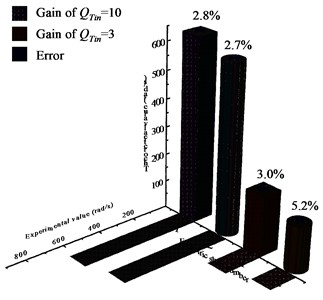
b) Comparison of experiment and theory
3.6. Uncertainty analysis of experimental data
To assess the reliability of the experimental rotational velocity measurements, an uncertainty analysis was conducted following the method described in JJF 1059.1‑2012 (consistent with the ISO GUM) [38]. The high‑flow condition ( 1×10⁻³ m3/s) is taken as an example.
The Type A standard uncertainty, denoted and representing measurement repeatability, was calculated from ten repeated measurements, giving 0.12 rad/s. The Type B standard uncertainty considered three sources: (i) rotational velocity sensor accuracy (±0.5 % full scale), yielding a component 6.04 rad/s (uniform distribution); (ii) data acquisition system error (< 0.1 %), giving 0.12 rad/s (uniform distribution); and (iii) display resolution (0.1 rad/s), giving μB3= 0.03 rad/s (uniform distribution). The combined Type B uncertainty was 6.04 rad/s.
The combined standard uncertainty was then obtained as ≈ 6.04 rad/s. With a coverage factor 2 (approximately 95 % confidence level), the expanded uncertainty is 12.1 rad/s. The deviation between the theoretical rotational velocity (650 rad/s) and the experimental mean (637.4 rad/s) is 12.6 rad/s, which is very close to the expanded uncertainty. This indicates that the experimental results support the theoretical model within the uncertainty bounds. The uncertainty budget is summarized in Table 2.
Table 2Uncertainty budget for rotational velocity measurement (example QTin= 1×10⁻³ m3/s)
Uncertainty component | Source | Type | Distribution | Standard uncertainty |
Measurement repeatability (10 times) | A | Normal | 0.12 (rad/s) | |
Rotational velocity sensor accuracy (±0.5 % FS) | B | Uniform | 6.04 (rad/s) | |
Data acquisition system error (< 0.1 %) | B | Uniform | 0.12 (rad/s) | |
Display resolution (0.1 rad/s) | B | Uniform | 0.03 (rad/s) | |
Combined standard uncertainty μC | 6.04 (rad/s) | |||
Expanded uncertainty (2, approx. 95 % confidence) | 12.1 (rad/s) | |||
4. Conclusions
The synchronous rotation of eccentric structures is widely utilized in mechanical applications. We investigated the synchronization characteristics of two eccentric shafts in a PHMS. The masses, eccentricities, and viscous damping coefficients of the two eccentric shafts were considered nonidentical owing to manufacturing and installation errors. The main conclusions can be outlined as follows:
1) The proposed mathematical model provided a maximum deviation rate of 8.9 % between the theoretical and simulation results and a maximum deviation rate of 5.2 % between the theoretical and experimental results, both within the allowable engineering range, indicating the validity and applicability of the proposed model.
2) In a PHMS, stable operation can still be achieved by two eccentric shafts with parameter differences. However, an ideal synchronous state with completely equal rotational speeds cannot be reached. Regardless, the system exhibits strong robustness against parameter variations. Therefore, manufacturing and installation errors commonly encountered in engineering can be tolerated.
3) The rotational velocity of an eccentric shaft is most sensitive to the viscous damping coefficient because viscous damping determines the rate of mechanical energy dissipation during shaft rotation and dominates the dynamic convergence process of the system. Consequently, it becomes the most influential factor affecting synchronization performance.
Our findings can provide a theoretical basis for the design of vibrating machinery, such as sonic drill rigs, pile drivers, and breakers. However, synchronization accuracy must be prioritized through damping parameter matching. Further, hydraulic configurations with short pipelines, low flow rates, and high sealing performance are recommended. These measures suppress flow fluctuations and leakage, enhancing system stability and synchronization reliability. Owing to space limitations, the synchronization characteristics of only two eccentric shafts in a PHMS were analyzed. In the future, the synchronization characteristics of multi-shaft systems will be investigated. In addition, full hydraulic factors such as pipeline pressure losses, external leakage, and oil viscosity-temperature characteristics will be introduced in multi-shaft models for consistency with actual working conditions. Furthermore, hybrid synchronization strategies will be discussed to further improve synchronization accuracy and adaptability under complex conditions.
References
-
Y. Wang, Q. Zhou, B. Liu, Z. Li, and M. Huang, “Design and model analysis of the sonic vibration head,” Journal of Vibroengineering, Vol. 17, No. 5, pp. 2121–2131, Aug. 2015, https://doi.org/10.21595/jve.2015.15873
-
T. Watkins, H. Askarinejad, and J. Yeo, “Investigation into effect of sonic drilling methodology on standard penetration test results in dense sand,” Geotechnical Testing Journal, Vol. 44, No. 3, pp. 824–832, May 2021, https://doi.org/10.1520/gtj20190249
-
S. Li, Y. Wang, H. Wu, and L. Liu, “Dynamic response of drill string when sonic drilling rig is applied to blasting hole operation,” Geoenergy Science and Engineering, Vol. 221, p. 211392, Dec. 2022, https://doi.org/10.1016/j.geoen.2022.211392
-
G. W. Luo and H. M. Yao, “Dynamics of a small vibro-impact pile driver,” Nonlinear Analysis: Real World Applications, Vol. 9, No. 4, pp. 1361–1377, Mar. 2007, https://doi.org/10.1016/j.nonrwa.2007.03.004
-
B. He, C. Zhao, H. Wang, X. Chang, and B. Wen, “Dynamics of synchronization for four hydraulic motors in a vibrating pile driver system,” Advances in Mechanical Engineering, Vol. 8, No. 8, pp. 168781401665904–168781401665904, Aug. 2016, https://doi.org/10.1177/1687814016659043
-
M. Zou, P. Fang, Y. Hou, Y. Wang, D. Hou, and H. Peng, “Synchronization analysis of two eccentric rotors with double-frequency excitation considering sliding mode control,” Communications in Nonlinear Science and Numerical Simulation, Vol. 92, p. 105458, Aug. 2020, https://doi.org/10.1016/j.cnsns.2020.105458
-
M. Zou, P. Fang, Y. Hou, and H. Peng, “Investigation on multiple-frequency synchronization experiment of vibration system with dual-rotor actuation,” Mechanical Systems and Signal Processing, Vol. 164, p. 108261, Jul. 2021, https://doi.org/10.1016/j.ymssp.2021.108261
-
A. S. Pikovsky, M. G. Rosenblum, G. V. Osipov, and J. Kurths, “Phase synchronization of chaotic oscillators by external driving,” Physica D: Nonlinear Phenomena, Vol. 104, No. 3-4, pp. 219–238, May 2003, https://doi.org/10.1016/s0167-2789(96)00301-6
-
I. I. Blekhman, A. L. Fradkov, H. Nijmeijer, and A. Y. Pogromsky, “On self-synchronization and controlled synchronization,” Systems and Control Letters, Vol. 31, No. 5, pp. 299–305, Oct. 1997, https://doi.org/10.1016/s0167-6911(97)00047-9
-
P. Fang, S. Shi, M. Zou, X. Lu, and D. Wang, “Self-synchronization and control-synchronization of dual-rotor space vibration system,” International Journal of Non-Linear Mechanics, Vol. 139, p. 103869, Nov. 2021, https://doi.org/10.1016/j.ijnonlinmec.2021.103869
-
I. I. Blekhman, Synchronization in Science and Technology. ASME Press, 1988.
-
B. Wen, J. Fan, C. Zhao, and W. Xiong, Vibratory Synchronization and Controlled Synchronization in Engineering. Beijing: Science Press, 2009.
-
B. C. Wen, H. Zhang, and S. Y. Liu, Theory and Techniques of Vibrating Machinery and Their Applications. Beijing, China: Science Press, 2010.
-
C. Zhao, H. Zhu, R. Wang, and B. Wen, “Synchronization of Two non-identical coupled exciters in a non-resonant vibrating system of linear motion. Part I: theoretical analysis,” Shock and Vibration, Vol. 16, No. 5, pp. 505–515, Jan. 2014, https://doi.org/10.1155/2009/259149
-
C. Zhao, H. Zhu, T. Bai, and B. Wen, “Synchronization of two non-identical coupled exciters in a non-resonant vibrating system of linear motion. Part II: numeric analysis,” Shock and Vibration, Vol. 16, No. 5, pp. 517–528, Jan. 2014, https://doi.org/10.1155/2009/826929
-
C. Zhao, Q. Zhao, Z. Gong, and B. Wen, “Synchronization of two self-synchronous vibrating machines on an isolation frame,” Shock and Vibration, Vol. 18, No. 1-2, pp. 73–90, Jan. 2014, https://doi.org/10.1155/2011/904204
-
X. Zhang, B. Wen, and C. Zhao, “Synchronization of three non-identical coupled exciters with the same rotating directions in a far-resonant vibrating system,” Journal of Sound and Vibration, Vol. 332, No. 9, pp. 2300–2317, Jan. 2013, https://doi.org/10.1016/j.jsv.2012.12.003
-
X. Zhang, B. Wen, and C. Zhao, “Vibratory synchronization transmission of two exciters in a super-resonant vibrating system,” Journal of Mechanical Science and Technology, Vol. 28, No. 6, pp. 2049–2058, Jun. 2014, https://doi.org/10.1007/s12206-014-0108-4
-
X. Zhang, B. Wen, and C. Zhao, “Experimental investigation on synchronization of three co-rotating non-identical coupled exciters driven by three motors,” Journal of Sound and Vibration, Vol. 333, No. 13, pp. 2898–2908, Mar. 2014, https://doi.org/10.1016/j.jsv.2014.01.022
-
X. Zhang, X. Kong, B. Wen, and C. Zhao, “Numerical and experimental study on synchronization of two exciters in a nonlinear vibrating system with multiple resonant types,” Nonlinear Dynamics, Vol. 82, No. 1-2, pp. 987–999, Oct. 2015, https://doi.org/10.1007/s11071-015-2212-0
-
X. Zhang, B. Wen, and C. Zhao, “Theoretical study on synchronization of two exciters in a nonlinear vibrating system with multiple resonant types,” Nonlinear Dynamics, Vol. 85, No. 1, pp. 141–154, Feb. 2016, https://doi.org/10.1007/s11071-016-2674-8
-
T. Zhang, B. Wen, and J. Fan, “Study on Synchronization of two eccentric rotors driven by hydraulic motors in one vibrating system,” Shock and Vibration, Vol. 4, No. 5-6, pp. 305–310, Jan. 2014, https://doi.org/10.1155/1997/319635
-
C.-L. Luo, X. Mo, J.-Y. Li, Z.-Q. Tang, and S.-S. Huang, “Coupling synchronization criterion of two hydraulic motors in an eccentric rotary vibration machine,” Shock and Vibration, Vol. 2019, No. 1, pp. 1–11, Jan. 2019, https://doi.org/10.1155/2019/6086874
-
Y. Wang and C. Zhao, “Investigation on self-synchronization of two unbalanced rotors driven by two hydraulic motors in a vibrating pile driver,” Mechanics Based Design of Structures and Machines, Vol. 53, No. 11, pp. 7711–7736, Nov. 2025, https://doi.org/10.1080/15397734.2025.2498086
-
R. Shu, J. Wei, R. Tan, X. Wu, and B. Fu, “Investigation of dynamic and synchronization properties of a multi-motor driving system: Theoretical analysis and experiment,” Mechanical Systems and Signal Processing, Vol. 153, p. 107496, Dec. 2020, https://doi.org/10.1016/j.ymssp.2020.107496
-
J. Wei, R. Shu, D. Qin, T. C. Lim, A. Zhang, and F. Meng, “Study of synchronization characteristics of a multi-source driving transmission system under an impact load,” International Journal of Precision Engineering and Manufacturing, Vol. 17, No. 9, pp. 1157–1174, Sep. 2016, https://doi.org/10.1007/s12541-016-0140-7
-
X. Kong, X. Zhang, X. Chen, B. Wen, and B. Wang, “Synchronization analysis and control of three eccentric rotors in a vibrating system using adaptive sliding mode control algorithm,” Mechanical Systems and Signal Processing, Vol. 72-73, pp. 432–450, Nov. 2015, https://doi.org/10.1016/j.ymssp.2015.11.007
-
X. Kong, X. Zhang, X. Chen, B. Wen, and B. Wang, “Phase and speed synchronization control of four eccentric rotors driven by induction motors in a linear vibratory feeder with unknown time-varying load torques using adaptive sliding mode control algorithm,” Journal of Sound and Vibration, Vol. 370, pp. 23–42, Feb. 2016, https://doi.org/10.1016/j.jsv.2016.02.013
-
X. Kong, C. Chen, and B. Wen, “Composite synchronization of three eccentric rotors driven by induction motors in a vibrating system,” Mechanical Systems and Signal Processing, Vol. 102, pp. 158–179, Sep. 2017, https://doi.org/10.1016/j.ymssp.2017.09.025
-
J. Li, Y. Wang, L. Kong, Y. Sun, H. Wu, and J. Qu, “Investigation of stability and synchronization properties of two oscillators in a solid-liquid coupling system,” International Journal of Mechanics and Materials in Design, Vol. 18, No. 4, pp. 823–836, Dec. 2022, https://doi.org/10.1007/s10999-022-09606-9
-
J. Li, Y. Wang, and L. Kong, “Synchronization characteristics of two vibrators in a novel hydraulic coupling system,” Alexandria Engineering Journal, Vol. 61, No. 12, pp. 11663–11676, May 2022, https://doi.org/10.1016/j.aej.2022.05.040
-
K. Hu and W. Zhang, “Precise control algorithm of rotational speed of the valve-controlled hydraulic motor under load fluctuating conditions,” Science Progress, Vol. 107, No. 4, pp. 00368504241296299–368504241296299, Nov. 2024, https://doi.org/10.1177/00368504241296299
-
W. Du, Y. Luo, Y. Luo, and H. Mu, “A simulation study of an electro-hydraulic load-sensitive variable pressure margin diverter synchronous drive system with time-varying load resistance,” Processes, Vol. 12, No. 1, p. 170, Jan. 2024, https://doi.org/10.3390/pr12010170
-
B. Wang, X. Yang, B. Hou, Y. Li, Y. Chen, and X. Peng, “Performance analysis and structural optimization of VL-type hydraulic reciprocating seal in a deep-sea hydraulic system,” Ocean Engineering, Vol. 328, p. 121048, Mar. 2025, https://doi.org/10.1016/j.oceaneng.2025.121048
-
Z. Song, J. Hong, Z. Yang, Y. Cao, and Y. Ma, “Dynamical analysis of propeller rotors whirl flutter considering complex blade geometries and induced velocities,” Mechanical Systems and Signal Processing, Vol. 230, p. 112621, Mar. 2025, https://doi.org/10.1016/j.ymssp.2025.112621
-
C. Chen and Q. Zhan, “Simulation and analysis of hydraulic transition process based on mechanical hydraulics,” PLOS ONE, Vol. 18, No. 12, p. e0295044, Dec. 2023, https://doi.org/10.1371/journal.pone.0295044
-
A. Najdecka, T. Kapitaniak, and M. Wiercigroch, “Synchronous rotational motion of parametric pendulums,” International Journal of Non-linear Mechanics, Vol. 70, pp. 84–94, Oct. 2014, https://doi.org/10.1016/j.ijnonlinmec.2014.10.008
-
M. Mikielewicz, F. Kazemi, and R. Jankowski, “Data-driven predictive model and uncertainty analysis of vehicle-induced vibrations based on experimental measurements,” Mechanical Systems and Signal Processing, Vol. 254, p. 114336, May 2026, https://doi.org/10.1016/j.ymssp.2026.114336
About this article

This work was supported by the Zhejiang Provincial Natural Science Foundation of China (No. LQN26E090012) and the Doctor Scientific Research fund of Changzhou Vocational Institute of Industry Technology (No. GCC202413101015).
The datasets generated during and/or analyzed during the current study are available from the corresponding author on reasonable request.
Jiong Li: conceptualization, methodology, formal analysis, writing-original draft. Shouceng Deng: software, validation, data curation, writing-review and editing. Jiaxing Lu: investigation, supervision, resources, project administration. All authors have read and approved the final version of the manuscript.
The authors declare that they have no conflict of interest.

