Abstract
The roof of a swimming pool is supported by a 33.6 m-span post-tensioned bonded prestressed concrete frame, in which the presence of a heavy upper transfer structure and superimposed filling loads significantly complicates the structural behavior. This study presents a comprehensive investigation of such structural systems based on a practical engineering project. A refined analytical framework is developed to evaluate the flexural capacity, stiffness, deflection, and crack width of prestressed concrete frame beams, with particular consideration of prestress effects and secondary internal forces induced by the transfer structure. In addition, a performance-oriented design approach incorporating ductility requirements and vertical seismic effects is proposed. A three-dimensional global analysis is adopted to capture the interaction between structural components and to improve the accuracy of dynamic response evaluation. The results indicate that the presence of the upper transfer structure significantly affects internal force redistribution, and the induced secondary internal forces must be carefully considered in design. The proposed system demonstrates favorable structural performance in terms of load-carrying capacity, ductility, and seismic behavior under heavy loading conditions. Compared with conventional design approaches, this study highlights the importance of considering the coupled effects of prestressing and transfer systems, and provides practical design recommendations, including reinforcement configurations and construction procedures. The findings offer useful guidance for the analysis and design of similar long-span prestressed concrete structures with transfer systems.
Highlights
- A large-span bonded post-tensioned prestressed concrete frame with a transfer structure is developed and analyzed.
- Prestressing improves the stiffness, crack resistance, and load-transfer performance of the large-span frame.
- Secondary internal forces induced by the transfer structure are quantified and incorporated into the structural design.
- Plastic moment redistribution is used to optimize the bending moment distribution of prestressed concrete frame beams.
- The proposed design provides favorable seismic performance and efficient structural material utilization.
1. Introduction
Due to their superior structural performance, long-span post-tensioned, bonded prestressed concrete frame systems have seen increasing adoption in large public buildings, long-span cantilevered structures, heavy-load industrial buildings, and high-rise constructions. In response to this increasing application, the Code for Design of Concrete Structures (GB50010-2010) [1], developed from comprehensive theoretical studies and engineering practice, incorporates calculation formulas and detailing requirements specific to long-span post-tensioned, bonded prestressed concrete frame beams. The code explicitly states that post-tensioned bonded prestressing technology can significantly enhance the energy dissipation capacity of long-span concrete frame beams under seismic loading and improve their seismic performance, establishing it as one of the principal structural systems for long-span, heavy-load applications.
Compared with unbonded prestressed concrete frame systems, bonded prestressed concrete frames demonstrate superior serviceability and load-carrying capacity, owing to the improved interaction between prestressing tendons and concrete. Unlike pretensioned concrete frames, where the bond between tendons and concrete relies solely on adhesion, post-tensioned bonded prestressed concrete frames benefit from the combined effects of end anchorage and bond interaction, thereby enhancing structural performance and safety margins [2-5]. Hussien et al. [6] studied the structural behavior of bonded prestressed concrete beams, reporting that raising the concrete compressive strength from 72 MPa to 97 MPa increased the ultimate load and cracking load by approximately 4 % and 18 %, respectively. Lee et al. [7] performed shear tests on four conventionally reinforced beams and seven post-tensioned concrete beams, concluding that stirrups effectively controlled diagonal crack widths, while prestressing mainly delayed crack initiation. Svanbäck et al. [8] suggested that, in post-tensioned concrete beams, steel ducts better maintain geometric integrity than plastic ducts, thereby reducing the number of visible cracks. Zhou et al. [9] experimentally examined post-tensioned bonded prestressed concrete beams, observing that, after concrete cracking, the beams could still sustain substantial loads, even if the prestressing tendon anchorage system failed. Zhang et al. [10] experimentally studied the flexural behavior of post-tensioned bonded reinforced concrete beams under steel strand corrosion, elucidating its effects on mechanical responses, including ultimate load capacity and ductility. Results indicated that severe corrosion reduced crack numbers, shifted the failure mode from concrete crushing to strand rupture, and substantially decreased both ductility and ultimate load capacity. Finite element analysis has been widely used to provide comprehensive insights into the mechanical behavior of prestressed concrete beams, including material damage evolution and stress development in reinforcement and prestressing steel. Ngo and Scordelis [11] emphasized that accurate modeling of bond conditions between concrete and prestressing tendons is essential for simulating various prestressed concrete systems. The finite element program developed by Van Greunen and Scordelis [12] can analyze prestressed slabs with different prestressing systems. This program was subsequently integrated into the computational platform, enabling the consideration of time-dependent effects, as well as material and geometric nonlinearities.
El-Mezaini and Citipitioglu [13] proposed a discrete contact formulation to simulate bonded, fully unbonded, and partially bonded behaviors of reinforcing steel. A key feature of this formulation is the introduction of linear springs between overlapping concrete and reinforcement nodes to represent partial bonding. Kang et al. [14] developed finite element models for unbonded and bonded prestressed concrete structures. The grouting process in post-tensioned bonded prestressed systems was simulated by modifying the tangential contact behavior from “frictionless” to infinitely “rough,” and surface-to-surface contact was used to model the steel–concrete interaction. However, the numerical results showed poor convergence. Therefore, establishing appropriate contact conditions between reinforcement and concrete, along with suitable constitutive models, is critically important. Lee et al. [15] conducted finite element analyses of reinforced concrete beams and externally post-tensioned prestressed concrete beams. The mechanical behavior of concrete was modeled using the concrete damaged plasticity (CDP) model in ABAQUS. By assuming a perfect bond between reinforcement and concrete and properly calibrating the CDP model parameters, the challenges of explicitly modeling bond–slip behavior were effectively avoided. The simulation results agreed well with experimental observations regarding strength, deflection, and stress responses of the external prestressing tendons. Additionally, Coronelli et al. [16] developed a numerical model of post-tensioned bonded reinforced concrete beams to simulate the effects of stress corrosion failure of prestressing tendons under service conditions. Incorporating interface elements allowed reproduction of different stages of tendon wire fracture and beam loading, enabling the investigation of various failure modes associated with wire breakage. In theoretical studies of post-tensioned bonded prestressed structures, Stanton [17] analyzed prestress losses due to friction and slip and proposed corresponding numerical solutions. Mirza et al. [18] studied the short-term ultimate flexural strength of pretensioned and post-tensioned bonded prestressed concrete beams. Using a Monte Carlo approach to randomly vary material strengths and geometric properties, they suggested that the strength reduction factor for post-tensioned bonded concrete beams can generally be assumed to be 0.9. Hussien et al. [6] established moment-curvature relationships at various cross-sections using an iterative approach that satisfies strain compatibility and force equilibrium. The maximum deflection of post-tensioned bonded prestressed beams was then determined through curvature integration.
Recent studies have extensively explored the mechanical behavior, seismic performance, and modeling approaches of prestressed concrete and composite structural systems. For example, prestressed steel–concrete composite systems have been proposed to enhance structural performance through the combined use of prestressing and steel components [19]. Experimental investigations have also been conducted to evaluate progressive collapse resistance and structural robustness under extreme conditions such as column removal [20]. In recent years, further studies have extended these investigations to dynamic and impact responses of prestressed concrete members using both experimental and numerical approaches [21-22].
In addition, significant efforts have been devoted to the assessment of prestress levels and structural performance, including the evaluation of residual prestress in post-tensioned members [23] and the modeling of energy dissipation in dynamic systems [24]. Research on structural dynamics has further clarified vibration characteristics and responses under different loading conditions, including periodic and impulsive excitations [25]. Recent studies have also investigated modal properties and dynamic characteristics of concrete structures through numerical and sensitivity-based approaches, highlighting the importance of accurately capturing stiffness variations and damage effects in dynamic analysis [26-27].
From a numerical perspective, advanced finite element modeling techniques have been widely applied to simulate the behavior of prestressed and reinforced concrete structures. These include nonlinear FE modeling of CFRP-strengthened members [28], cohesive zone-based modeling of hybrid connections [29], bond-slip modeling in reinforced concrete members [30], and multiscale simulation approaches for seismic performance evaluation [31]. In addition, hybrid computational methods combining finite element analysis and artificial intelligence have been developed to predict structural behavior more efficiently [32]. More recently, high-fidelity numerical approaches have been adopted to simulate complex structural components and connections with improved accuracy [33].
Despite these advances, limited studies have addressed the structural behavior and design methodology of long-span post-tensioned bonded prestressed concrete frames with upper transfer structures, particularly under the coupled effects of prestressing, transfer systems, and seismic actions. Existing studies indicate that both the theoretical understanding and practical applications of post-tensioned bonded prestressed concrete frame structures have become increasingly mature. In engineering practice, cast-in-place floor and roof slabs are commonly used to connect long-span prestressed concrete beams, enabling composite action between beams and slabs. However, under certain functional requirements, such as buildings requiring large story heights, large openings may be needed between prestressed concrete beams, making it impractical to connect long-span beams using cast-in-place slabs. In such cases, to simultaneously satisfy functional requirements and ensure structural stability, a transfer frame system is typically arranged above the long-span prestressed concrete beams. Consequently, the lower prestressed concrete beams and the upper transfer frame form a composite structural system, referred to as a long-span post-tensioned bonded prestressed concrete frame with an upper transfer system. For this type of structural system, current design codes are insufficient to fully meet the design requirements. This is mainly reflected in the following aspects: the presence of an upper transfer structure induces secondary internal forces due to prestressing–transfer interaction, which are difficult to accurately evaluate; moreover, ductility-based seismic design is not adequately considered for long-span prestressed beams. Neglecting these issues in engineering practice may lead to potential structural risks and increased construction complexity.
To address the above research gaps and engineering challenges, this study presents a systematic investigation of long-span post-tensioned bonded prestressed concrete frame structures with an upper transfer system based on a practical engineering project. The main novelties and contributions of this study are summarized as follows: (1) A refined analytical framework is developed to explicitly account for the coupled effects of prestressing and upper transfer structures, with particular emphasis on the evaluation of secondary internal forces in statically indeterminate systems. (2) A three-dimensional global modeling approach is established by incorporating slab–beam interaction and transfer structure effects, thereby overcoming the limitations of conventional two-dimensional frame analysis. (3) A performance-oriented design methodology is proposed, integrating prestress level control, ductility-based design, and the consideration of vertical seismic actions for long-span prestressed beams. (4) Based on analytical and numerical results, practical design recommendations and construction strategies are provided, offering guidance for the analysis and design of similar complex structural systems.
2. Engineering overview
The redevelopment and resettlement housing project of an urban village in Anning District, Lanzhou City, is situated at the intersection of the planned roads T511, T550, S554, and S583. The site spans approximately 365 m in the east-west direction and 330-445 m in the north-south direction. The terrain is generally flat, with elevations higher in the northwest and lower in the southeast. The proposed development is divided into two zones: southern and northern.
The southern zone comprises nine high-rise residential buildings (Buildings 1-9), a primary school building (Building 31), a kindergarten (Building 32), and an underground parking garage. The northern zone includes six high-rise residential buildings (Buildings 13-14 and 27-30), an office building (Building 36), and an underground parking garage. Buildings 1-4, 7, 14, 27, and 29-30 each have 33 above-ground stories. For these buildings, the first through fourth floors of the main towers accommodate street-facing commercial spaces, whereas the fifth floor and above serve residential functions. The left section of Building 6 also has 33 above-ground stories, with the first and second floors housing a kindergarten, and the third floor and above designated for residential use. The remaining high-rise residential buildings are solely dedicated to residential use. Building 31 (the primary school) has four above-ground stories and an L-shaped floor plan. A seismic isolation layer is installed between the underside of the first-floor slab and the foundation’s top surface, classifying the building as a base-isolated structure.
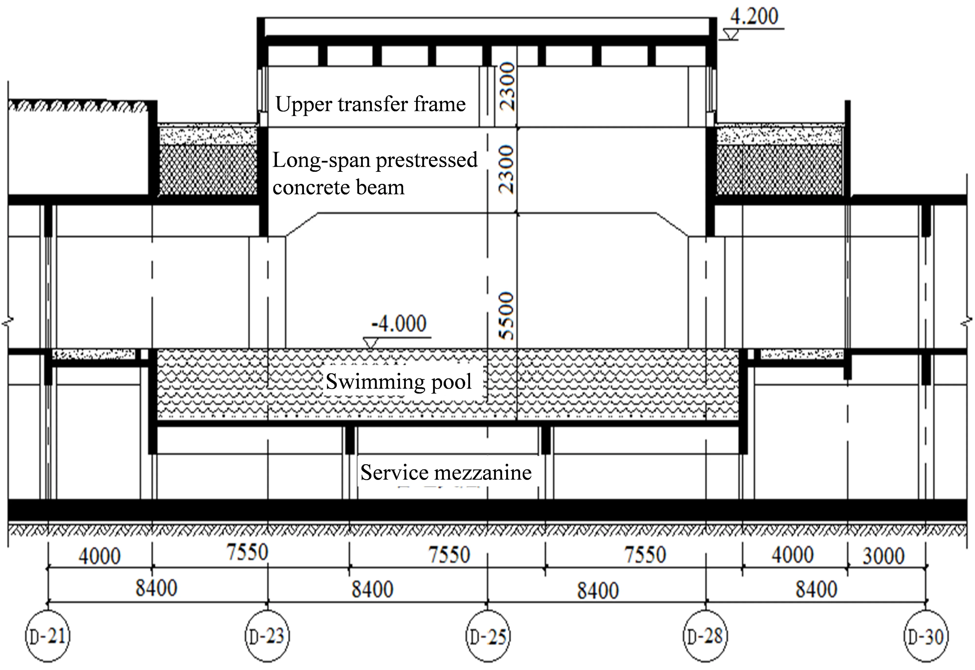
Fig. 1Building section
The northern underground parking garage has two basement levels and is connected to the B2-B3 basements of Buildings 14 and 27-30. The maximum plan dimensions are 131.60×147.85 m, with a soil cover thickness ranging from 1.55 to 2.25 m above the garage roof slab. The southern underground parking garage likewise comprises two basement levels and is connected to the B2-B3 basements of Buildings 1-9. A passage on the north side of the B1 level connects to the Phase I parking garage. The maximum plan dimensions are 344.0×189.6 m, with a soil cover thickness above the roof slab ranging from 1.7 to 2.4 m.
The swimming hall is an underground facility situated within the northern zone’s underground parking garage. It is located at the first basement level (B1), featuring a floor-to-ceiling height of 7.8 m and plan dimensions of 40×40 m. The swimming hall roof is formed by the basement roof slab, above which a transfer structure and substantial superimposed loads, including soil fill, are applied. The project is designed for a service life of 50 years, with a structural safety classification of Class II. The seismic fortification intensity is 8, the design basic seismic acceleration is 0.2 g, the design earthquake group is Group III, and the site is classified as Category II. Fig. 1 presents a sectional view of the building.
3. Structural system selection and prestressing layout
3.1. Structural system selection
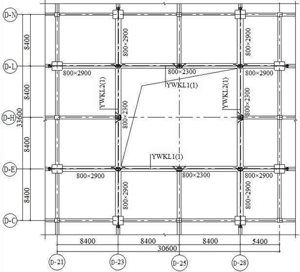
In selecting the structural scheme, consideration was given to the presence of an upper transfer structure, substantial superimposed loads-including soil fill-on the basement roof slab, and the relatively large span of 33.6 m. Following a comprehensive evaluation of functional requirements, construction costs, and constructability, alongside comparative technical analyses, a prestressed concrete frame system was adopted. Fig. 2 illustrates the plan layout of the prestressed concrete frame.
Fig. 2Layout plan of prestressed beam with elevation of 1.900
3.2. Prestressing layout
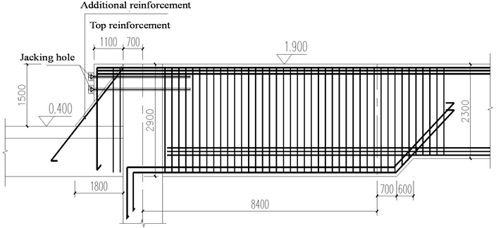
Due to higher bending moments at the supports compared to midspan, variable-depth prestressed frame beams with end haunches were adopted. The cross section at midspan measures 800 mm×2300 mm, whereas the section at the supports includes vertical haunches, increasing the dimensions to 800 mm×2900 mm. Structural analysis results indicate that employing variable-depth beams effectively mitigates peak stresses. Fig. 3 illustrates the haunch configuration at the beam supports.
Fig. 3Beam end support haunching
4. Prestressed structural analysis
4.1. Prestressing procedures and control parameters
The prestressing tendons are composed of 15 low-relaxation steel strands (1×7 configuration, nominal diameter 15.24 mm) with a characteristic tensile strength of 1860 MPa. The jacking control stress of the prestressing tendons, , is taken as 0.75 . HVM-series extrusion anchors are employed at the fixed ends of the tendons, whereas HVM-series wedge anchors are used at the stressing ends. Given the relatively long tendon lengths, a two-end stressing scheme is implemented. Prestressing ducts are constructed using pre-embedded corrugated metal sheaths, with the internal diameter of each duct 10-15 mm larger than the outer diameter of the tendon bundle. Cement-based grout is employed for tendon grouting and is prepared using ordinary Portland cement mixed with water. The water-to-cement ratio is limited to a maximum of 0.42, and the grout compressive strength is required to be at least 30 N/mm2.
The prestressed frame beams are designed to satisfy both the ultimate limit state (ULS) and the serviceability limit state (SLS) requirements. In this project, the prestressed frame beams are primarily evaluated in terms of flexural capacity, stiffness, deflection, and crack control. According to the Code for Design of Concrete Structures (GB 50010-2010), the crack control level is specified as Grade III. Based on standard load combinations and considering long-term loading effects, the allowable deflection of the prestressed frame beams is limited to 1/400 of the calculated span.
4.2. Layout and preliminary estimation of prestressing tendons
The prestressing tendons in the prestressed concrete frame beams were arranged in a two-segment parabolic profile, with the tendons positioned as close as possible to the cross-sectional centroid at the anchorage zones. The inflection points of the tendons within the span were located at 0.1 times the span length from the supports. Based on multiple trial calculations, a four-duct tendon layout was adopted, and the corresponding arrangement is illustrated in Fig. 4.
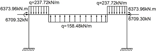
The prestressing tendons were initially estimated using the load-balancing method. Considering the transfer structures and heavy soil backfill above the basement roof, the prestressing level of the frame beams was deliberately reduced to improve structural ductility, thereby reducing the magnitude of the balanced loads. The balanced load was assumed to be approximately 80 % of the permanent load. The equivalent prestressing load distribution is illustrated in Fig. 5, and the resulting sectional control stresses were confirmed to satisfy the criteria for crack control and deflection.
Fig. 4Schematic diagram of prestressed reinforcement layout
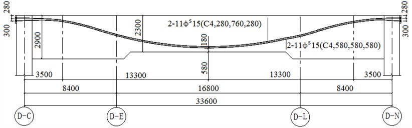
Fig. 5Equivalent load diagram of prestress
4.3. Analysis of prestressing effects
A three-dimensional structural model for this project was established using YJK and MIDAS-FEA. Since the analysis of prestressing effects typically addresses issues related to vertical loading, a two-dimensional single-frame model can be employed for the frame structures to simplify calculations, neglecting the influence of adjacent vertical members. However, due to the large span of the prestressed beams and the presence of an upper transfer structure, it is necessary to conduct supplementary analyses using a three-dimensional global model in addition to the single-plane frame analysis. These analyses explicitly account for the effects of floor slabs and the transfer structure, providing a comprehensive evaluation of their influence.
4.3.1. Prestress losses
Prestress losses were calculated following the relevant provisions of the Code for Design of Concrete Structures (GB 50010-2010) [1], and the total prestress loss is shown in Fig. 6. For computational convenience, prestress losses in each span were averaged and analyzed using the two-dimensional single-frame model. The average prestress loss was determined to be 335 N/mm2. This prestress loss corresponds to approximately 24 % of the jacking control stress, in good agreement with the initial estimation.
4.3.2. Internal force analysis under equivalent prestressing loads
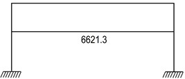
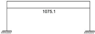
Under equivalent prestressing loads, the total and secondary bending moments of the prestressed concrete frame beams are shown in Fig. 7, while the total and secondary axial forces are presented in Fig. 8. Due to the presence of a transfer structure above the prestressed concrete frame beams and the heavy roof loads from soil fill, the effects of secondary internal forces must be carefully considered. Secondary axial forces result from the axial deformation of the prestressed frame beam restrained by surrounding frame columns. Accordingly, the secondary axial force in the beam corresponds to the secondary shear force in the frame columns. Due to the relatively large cross-sectional dimensions of the frame columns, the secondary axial force in the prestressed frame beam accounts for approximately 16.2 % of the equivalent prestressing loads at both tendon ends, indicating that secondary internal forces should be fully considered in the structural analysis.
Fig. 6Distribution of prestress loss
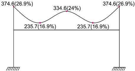
Fig. 7Comprehensive bending moment and secondary bending moment of prestressed concrete frame beams
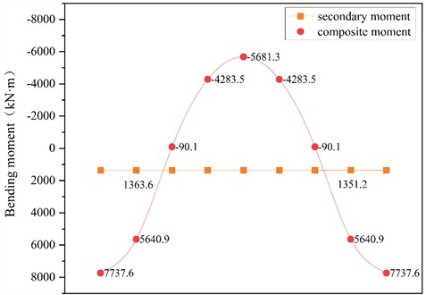
Fig. 8Comprehensive axial force and secondary axial force of prestressed concrete frame beams
a) Total axial force
b) Secondary axial force
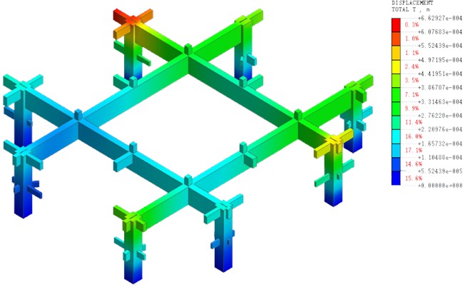
To further refine the internal force distribution of the prestressed concrete frame beams, supplementary analyses were performed using MIDAS FEA based on a three-dimensional global model. The long-span prestressed concrete frame beam and its connected components were selected for finite element analysis. Specifically, the prestressing tendon model was first established in MIDAS FEA, followed by modeling of the non-prestressed reinforcement and concrete. Interaction between these components was implemented using Boolean operations. The concrete was then discretized with a uniform mesh size of 550 mm, and the corresponding material properties were assigned. After mesh generation, seismic actions and other applied loads were applied to the MIDAS FEA solid model based on the results from the YJK global analysis. Analysis cases were then defined, considering geometric nonlinearity, and simulations were executed to obtain the results. Fig. 9 shows the stress contour of the prestressed concrete frame beam obtained from finite element analysis under vertical loads only. The results indicate that, under equivalent prestressing loads, the stress distribution along the prestressed concrete frame beam is fairly uniform.
Fig. 9Stress distribution nephogram of prestressed concrete frame beams
4.3.3. Deflection and crack width calculations of prestressed concrete frame beams
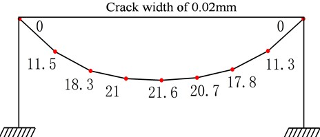
In prestressed concrete frame systems, secondary internal forces induced by lateral force-resisting components generally appear as tensile forces, causing the prestressed concrete frame beams to behave as tension-bending members. Therefore, the crack widths and deflections of the prestressed concrete beams must be carefully evaluated and controlled. Fig. 10 shows the deflections and crack widths of the prestressed concrete frame beam under the standard load combination. Under the standard load combination, the maximum deflection of the prestressed concrete frame beam is 21.6 mm. The crack width at the top of the beam is 0.02 mm, whereas that at the bottom is 0.01 mm. These values comply with the relevant provisions of the Code for Design of Concrete Structures (GB 50010-2010) [1].
Fig. 10Deflection and crack of prestressed concrete frame beams
5. Seismic performance analysis considering earthquake effects
5.1. Development of the numerical model
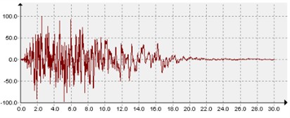
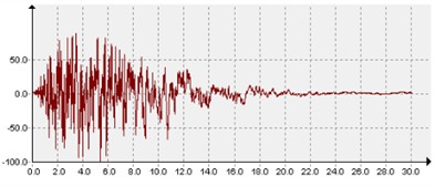
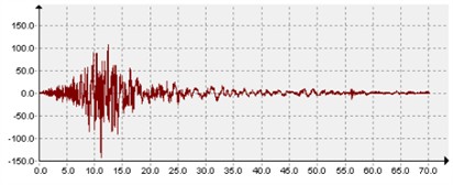
Elastic-plastic dynamic time-history analyses were conducted using MIDAS FEA. The characteristic period was set to 0.50 s, with a period reduction factor of 1.0, and wind loads were neglected. Based on Site Class II and the third seismic group (characteristic period 0.50 s), three ground motion records provided by the software were selected. The selected ground motions were applied as bidirectional horizontal inputs. For the rare earthquake level, the peak ground acceleration was 400 cm/s2 in the principal direction and 340 cm/s2 in the secondary direction (0.85×400 cm/s2). The time histories of the three ground motions are presented in Fig. 11, and Fig. 12 compares the design response spectrum specified by the code with the response spectra of the MIDAS FEA ground motions.
The validity of the numerical model is supported by the consistency of key dynamic characteristics, including the total structural mass, modal participation ratios, and the first several natural frequencies, which are in agreement with the expected behavior of reinforced concrete structures. Therefore, the model is considered capable of capturing the global dynamic response of the system and can be used for subsequent seismic analysis. Nevertheless, several assumptions have been adopted in the present study, including idealized boundary conditions and simplified representations of the bond behavior between prestressing tendons and concrete. As a result, the proposed analysis method and corresponding conclusions are subject to certain limitations.
First, the structural system considered in this study is a long-span post-tensioned bonded prestressed concrete frame with an upper transfer structure. To ensure effective transmission of horizontal seismic forces, cast-in-place floor slabs are required to connect the prestressed beams. When openings are introduced in the transfer floor due to functional requirements, the remaining effective slab area should be sufficient to maintain structural integrity and load transfer capacity. Second, the applicability of the proposed method is influenced by structural configuration parameters. In general, the span of transfer beams and the magnitude of superimposed loads (such as soil backfill) should be controlled within a reasonable range to ensure the effectiveness of prestressing and structural performance. For cases involving excessive superimposed loads, alternative lightweight materials may be required. Third, the presence of the upper transfer structure and prestressing effects induces significant secondary internal forces, which play a critical role in structural behavior. Accurate evaluation of these effects requires an appropriate structural configuration, and the conclusions of this study are primarily applicable to systems with relatively regular transfer structures.
Fig. 11Acceleration time histories of ground motions
a) TH1 ground motion
b) TH2 ground motion
c) RH1 ground motion
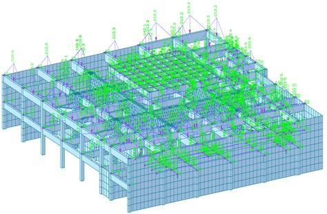
A global finite element model of the prestressed concrete frame beams and the overlying transfer frame was directly established in MIDAS FEA. The prestressed concrete transfer beam and its connected structural components were selected for detailed finite element analysis. Specifically, the prestressing tendon model was first established in MIDAS FEA, followed by the modeling of non-prestressed reinforcement and concrete. The interaction among these components was achieved through Boolean operations to ensure proper model coupling. Subsequently, the prestressed concrete frame beams were discretized with a uniform mesh size of 550 mm, and appropriate material properties were assigned. The global finite element model is presented in Fig. 13. After mesh generation, seismic actions and other applied loads were applied to the global solid model. The analysis cases were defined considering geometric nonlinearity, and simulations were performed to obtain the results. The solid loading model is shown in Fig. 14.
Fig. 12Comparison chart between standard spectrum and seismic spectrum
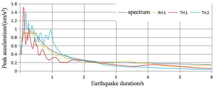
Fig. 13Overall calculation model
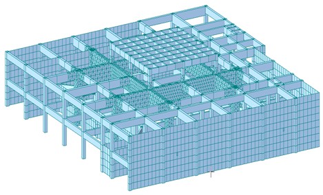
Fig. 14Overall loading model
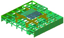
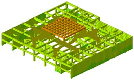
The modal properties of the first three modes of the global model are shown in Fig. 15, where the first mode corresponds to global translation in the direction, the second mode represents global translation in the direction, and the third mode is dominated by overall torsion. In the finite element analysis, solid elements were used to model the concrete, truss elements were adopted to represent the prestressing tendons, and shared-node or bond elements were employed to simulate the bonded interaction. Prestressing was applied using the equivalent load method, with prestress losses, secondary internal forces, and geometric nonlinearity taken into account. Refined modeling was performed for the transfer-level joints to capture the stress distribution and potential failure behavior within the joint core region.
Fig. 15Modal properties of the first three modes of the global model
a) First modal response
b) Second modal response
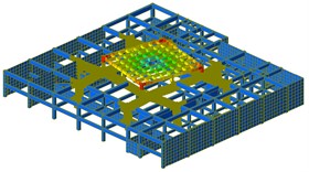
c) Third modal response
The modal results indicate that the complex statically indeterminate system, composed of long-span post-tensioned bonded prestressed concrete frame beams and an upper transfer frame, effectively resolves the structural conflict between large-span requirements and vertical functional transformation. The post-tensioned bonded prestressing provides high compressive pre-stress, enhanced stiffness, improved crack resistance, and self-centering capability, making it well suited for long-span structures subjected to dynamic loading. By investigating the dynamic characteristics, vibration response, and failure mechanisms under the coupled effects of prestressing and the transfer structure, this study addresses gaps in current codes and research, and provides theoretical and methodological support for seismic design, vibration control, construction monitoring, and structural safety assessment.
Table 1Natural frequencies and model participation factors of the structure
Mode No. | 1 | 2 | 3 | 4 | 5 | 6 | |
Natural frequency | 6.464 | 6.854 | 7.692 | 9.662 | 11.364 | 13.441 | |
Mass participation ratio (%) | direction | 91.16 | 91.19 | 99.73 | 90.11 | 91.00 | 77.14 |
direction | 99.84 | 99.94 | 99.95 | 80.91 | 77.22 | 75.23 | |
Torsional | 91.78 | 91.80 | 91.87 | 90.91 | 86.51 | 65.21 | |
Table 1 summarizes the modal properties of the structure, including natural frequencies and modal participation factors for the first six modes. The results show that the cumulative mass participation ratios in the principal directions exceed 99 %, with the first three modes contributing the majority of the mass participation. This indicates that the global dynamic response of the structure is primarily governed by the lower-order modes, which is consistent with the expected behavior of long-span frame systems. The fundamental frequencies of the structure range from 6.4 to 13.44 rad/s, reflecting the relatively high global stiffness of the system. This can be attributed to the presence of bonded post-tensioned prestressing, which enhances structural continuity and increases the effective stiffness of the frame. As a result, the dominant vibration characteristics are less likely to coincide with the predominant period range of typical ground motions, thereby reducing the potential for resonance effects. In addition, due to the use of bonded post-tensioning, the prestressing tendons act compositely with the surrounding concrete, leading to improved initial stiffness and overall integrity. These characteristics contribute to a more stable dynamic response compared with conventional reinforced concrete frame systems.
The stress analysis results of the prestressed concrete frame beams are presented in Fig. 16. The results indicate that, under seismic loading, the stress distribution along the prestressed concrete frame beams is relatively uniform and is predominantly resisted by the prestressing tendons.
Fig. 16Stress analysis results of prestressed concrete frame beams under seismic load
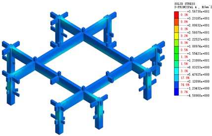
a) Stress distribution of concrete
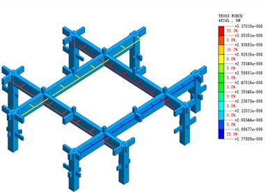
b) Stress distribution of prestressing tendons
5.2. Seismic performance analysis under horizontal earthquake loading
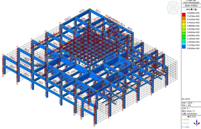
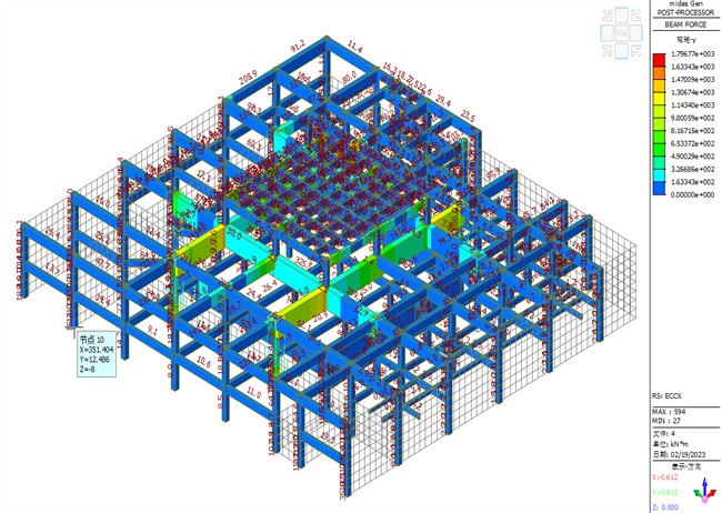
Based on the project’s actual conditions, a response spectrum was defined in the software, considering a seismic fortification intensity of 8, a design peak ground acceleration of 0.2 g, a third-group design earthquake, and a Class II site classification. Subsequently, numerical simulations were conducted on the global structural model. Fig. 17 shows the stress distribution of the global model under horizontal seismic excitation, indicating that stresses are distributed relatively uniformly. Fig. 18 presents the internal force distribution of the prestressed concrete frame beams under horizontal seismic loading. The results indicate that the prestressed concrete frame beams effectively transfer loads from the upper transfer structure, demonstrating satisfactory overall seismic performance.
Fig. 17Beam stress distribution under horizontal earthquake
5.3. Seismic performance analysis under vertical earthquake action
Owing to the relatively large span of the prestressed beams, vertical seismic forces are predominantly resisted by the prestressed concrete frame beams. Consequently, compared with horizontal seismic action, vertical ground motions exert a more pronounced effect on prestressed frame beams. Furthermore, the application of prestressing generates an “arching effect” in the vertical direction, enhancing the yielding resistance of prestressed concrete frame beams under vertical seismic loading. As a result, prestressed beams demonstrate a larger safety margin under vertical seismic loading compared with horizontal action.
Fig. 18Distribution of beam internal force under horizontal earthquake
To enhance the energy dissipation capacity of prestressed beams under seismic loading, a ductility-based design strategy can be adopted to ensure adequate seismic performance. Specifically, while satisfying the required bearing capacity, the configuration of prestressing tendons and non-prestressed reinforcement can be optimized by controlling the displacement ductility ratio. This approach can partially reduce construction complexity while improving the structural safety of prestressed concrete beams.
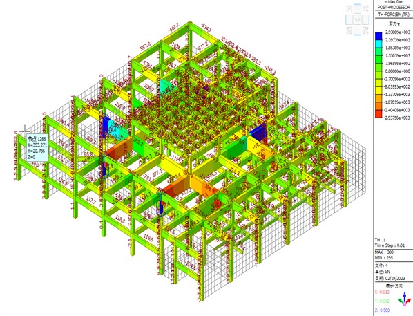
Time-history analyses were conducted using numerical software to simulate the response of the global model under vertical seismic loading. Fig. 19 shows the stress distribution of the global model under vertical seismic loading, with stresses primarily concentrated in the vertical members and prestressed beams. Fig. 20 presents the internal force distribution of the prestressed concrete beams under vertical seismic loading. The maximum shear force in the prestressed beams reaches 2930 kN. Therefore, particular attention should be given to the combination of vertical seismic load cases when defining structural load combinations.
The mechanical and dynamic behavior of long-span post-tensioned bonded prestressed concrete frames with an upper transfer structure is primarily governed by prestressing effects and structural coupling. Prestressing enhances stiffness, delays cracking, and induces secondary internal forces in statically indeterminate systems, while bonded interaction improves overall stability. The structure exhibits higher natural frequencies, reducing resonance risk; however, stiffness discontinuities at the transfer layer may lead to localized deformation concentration.
In addition, the system is sensitive to vertical excitation due to the relatively low vertical stiffness of long-span beams, and exhibits pronounced coupled flexural-shear-torsional responses under combined horizontal and vertical seismic actions. Nonlinear effects, including geometric, material, and bond-slip nonlinearities, may further influence the dynamic response. Based on these characteristics, appropriate dynamic analysis and design strategies are essential to ensure seismic safety and structural robustness.
Fig. 19Stress distribution of beam under vertical seismic action
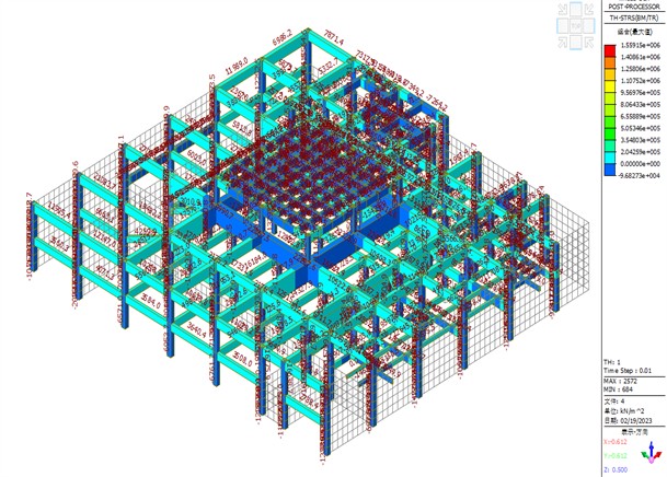
Fig. 20Distribution of beam internal force under vertical seismic action
6. Plastic moment redistribution design of prestressed concrete frame beams
Owing to the presence of an upper transfer structure and substantial superimposed loads, such as soil backfill, both horizontal and vertical seismic actions significantly affect the structural response of the long-span prestressed concrete beams. Considering the plastic redistribution of internal forces in prestressed concrete beams, a plastic moment redistribution design was consequently implemented for the prestressed concrete frame beams.
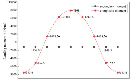
In the design calculations, vertical loads, together with horizontal and vertical seismic load cases, were considered, and the most critical load combinations were applied. Fig. 21 shows the internal force distribution of the prestressed concrete frame beams following plastic moment redistribution. Compared with the pre-redistribution results, the bending moments at the beam ends are significantly reduced, whereas the mid-span bending moments increase, yielding an overall moment redistribution ratio of approximately 15 %.
Based on the plastic moment redistribution design, beam reinforcement was optimized, reducing the reinforcement requirements at beam-column joints and clarifying the force-transfer mechanism. This approach effectively reduces construction complexity and substantially improves structural economy.
Fig. 21Comprehensive bending moment and secondary bending moment of prestressed concrete frame beam after amplitude modulation
7. Conclusions
This study, based on a practical swimming pool project, systematically investigates the applicability of bonded post-tensioned prestressed concrete frame structures for long-span beams supporting an upper transfer structure under heavy superimposed loads. Particular attention is given to the effects of secondary internal forces induced by the transfer structure. The main conclusions are as follows:
1) When an upper transfer structure and significant permanent loads are present, bonded post-tensioned prestressed concrete systems exhibit clear advantages in structural efficiency and load-carrying capacity. This is primarily attributed to the combined effects of prestressing-induced compressive stress and structural continuity. The use of variable-depth beams is recommended to reduce self-weight and improve material utilization.
2) For such structural systems, reliance solely on two-dimensional single-frame analysis may lead to unconservative results, as it cannot adequately capture slab–beam interaction and the influence of the transfer structure. A three-dimensional global or substructural model is therefore necessary to accurately represent force distribution and structural response.
3) Secondary internal forces induced by the transfer structure significantly influence structural behavior and must be carefully considered, as they alter both stress distribution and internal force paths within statically indeterminate systems. In addition to satisfying ultimate and serviceability limit states, ductility-based design should be incorporated to enhance seismic performance and deformation capacity.
4) The proposed design approach, integrating load-balancing prestress design and dynamic analysis, demonstrates that the system can achieve stable seismic performance. The synergistic effects of prestressing and structural configuration contribute to enhanced stiffness, improved force redistribution, and self-centering capability, resulting in a desirable beam-end plastic hinge mechanism, effective energy dissipation, and low residual deformation.
Overall, this study extends existing research by addressing the coupled effects of prestressing and upper transfer systems in long-span applications. Unlike conventional studies focusing on isolated members or simplified models, the proposed approach integrates three-dimensional global analysis with performance-oriented design, enabling a more accurate evaluation of secondary internal forces and seismic behavior. The results provide both mechanistic insights and practical guidance for the design of similar complex prestressed concrete structures.
References
-
“Code for design of concrete structures,” (in Chinese), China Building Industry Press, Beijing, GB50010-2010, 2010.
-
J. Janney, E. Hognestad, and D. Mchenry, “Ultimate flexural strength of prestressed and conventionally reinforced concrete beams,” Research and Development Laboratories, Vol. 52, No. 2, 1956, https://doi.org/10.14359/11618
-
N. Cooke, R. Park, and P. Yong, “Flexural strength of prestressed concrete members with unbonded tendons,” PCI Journal, Vol. 26, No. 6, pp. 52–81, Nov. 1981, https://doi.org/10.15554/pcij.11011981.52.81
-
A. Mattock, J. Yamazaki, and B. Kattula, “Comparative study of prestressed concrete beams, with and without bond,” ACI Journal Proceedings, Vol. 68, No. 2, pp. 116–125, 1971, https://doi.org/10.14359/11298
-
A. Tam and F. N. Pannell, “The ultimate moment of resistance of unbonded partially prestressed reinforced concrete beams,” Magazine of Concrete Research, Vol. 28, No. 97, pp. 203–208, 1976, https://doi.org/10.1680/macr.1976.28.97.203
-
O. F. Hussien, T. H. K. Elafandy, A. A. Abdelrahman, S. A. Abdel Baky, and E. A. Nasr, “Behavior of bonded and unbonded prestressed normal and high strength concrete beams,” HBRC Journal, Vol. 8, No. 3, pp. 239–251, May 2019, https://doi.org/10.1016/j.hbrcj.2012.10.008
-
S. C. Lee, J. Cho, and B. Oh, “Shear behavior of large-scale post-tensioned girders with small shear span-depth ratio,” ACI Structural Journal, Vol. 107, No. 2, pp. 116–117, Mar. 2010, https://doi.org/10.14359/51663529
-
A. Svanbäck, B. Ulén, and A. Etana, “Mitigation of phosphorus leaching losses via subsurface drains from a cracking marine clay soil,” Agriculture, Ecosystems and Environment, Vol. 184, No. 1, pp. 124–134, 2014, https://doi.org/10.1016/j.agee.2013.11.017
-
L. Zhou, A. D. G. Mahunon, G. Yin, and X. Xue, “Experimental investigation of simply-supported post-tensioned beam after anchorage system failure,” Engineering Structures, Vol. 212, p. 110507, Jun. 2020, https://doi.org/10.1016/j.engstruct.2020.110507
-
X. Zhang, L. Wang, J. Zhang, Y. Ma, and Y. Liu, “Flexural behavior of bonded post-tensioned concrete beams under strand corrosion,” Nuclear Engineering and Design, Vol. 313, pp. 414–424, Mar. 2017, https://doi.org/10.1016/j.nucengdes.2017.01.004
-
D. Ngo and A. Scordelis, “Finite element analysis of reinforced concrete beams,” ACI Journal Proceedings, Vol. 64, No. 3, pp. 152–163, 1967, https://doi.org/10.14359/7551
-
J. van Greunen and A. C. Scordelis, “Nonlinear analysis of prestressed concrete slabs,” Journal of Structural Engineering, Vol. 109, No. 7, pp. 1742–1760, Jul. 1983, https://doi.org/10.1061/(asce)0733-9445(1983)109:7(1742)
-
N. El‐Mezaini, C. Balkaya, and E. Çitipitiolu, “Analysis of frames with nonprismatic members,” Journal of Structural Engineering, Vol. 117, No. 6, pp. 1573–1592, Jun. 1991, https://doi.org/10.1061/(asce)0733-9445(1991)117:6(1573)
-
T. Kang et al., “Experimental and numerical assessment of bonded and unbonded post-tensioned concrete members,” ACI Structural Journal, Vol. 112, No. 6, pp. 735–748, Nov. 2015, https://doi.org/10.14359/51688194
-
S.-H. Lee, A. Abolmaali, K.-J. Shin, and H.-D. Lee, “ABAQUS modeling for post-tensioned reinforced concrete beams,” Journal of Building Engineering, Vol. 30, p. 101273, Jul. 2020, https://doi.org/10.1016/j.jobe.2020.101273
-
D. Coronelli, A. Castel, N. A. Vu, and R. François, “Corroded post-tensioned beams with bonded tendons and wire failure,” Engineering Structures, Vol. 31, No. 8, pp. 1687–1697, Aug. 2009, https://doi.org/10.1016/j.engstruct.2009.02.043
-
J. Stanton, “Effects of friction and slip-back on stresses in post-tensioning tendons,” in SP-231: Ned H Burns Symposium on Historic Innovations in Prestressed Concrete, Vol. 231, pp. 145–160, 2005, https://doi.org/10.14359/14925
-
S. Mirza, D. Kikuchi, and J. Macgregor, “Flexural strength reduction factor for bonded prestressed concrete beams,” ACI Journal Proceedings, Vol. 77, No. 4, pp. 237–246, 1980, https://doi.org/10.14359/7001
-
W. Wang et al., “Research on flexural performance of prestressed steel reinforced concrete frame-floor structure,” Journal of Building Engineering, Vol. 114, p. 114368, Nov. 2025, https://doi.org/10.1016/j.jobe.2025.114368
-
T. Qu, B. Zeng, C. Wu, L. Huang, J. Wu, and Z. Zhou, “Performance of Unbonded local prestressed concrete beam-column substructures against progressive collapse,” Journal of Structural Engineering, Vol. 151, No. 11, pp. 1–15, Nov. 2025, https://doi.org/10.1061/jsendh.steng-14665
-
J. Wang, B. Feng, and L. Chen, “Experimental and numerical study on impact resistance of external prestressed reinforced concrete beams,” Engineering Failure Analysis, Vol. 180, p. 109914, Oct. 2025, https://doi.org/10.1016/j.engfailanal.2025.109914
-
T. V. Do, T. M. Pham, A. Gehl, H. Hao, and T. P. Nguyen, “Impact responses of precast hollow reinforced concrete beams with prestress tendons using high-fidelity physics-based simulations,” Engineering Failure Analysis, Vol. 131, p. 105850, Jan. 2022, https://doi.org/10.1016/j.engfailanal.2021.105850
-
D. Rossi, C. Pettorruso, V. Quaglini, and S. Cattaneo, “An explorative investigation of the flat-jack test for prestress assessment in post-tensioned concrete structures,” Applied Sciences, Vol. 15, No. 11, p. 6199, May 2025, https://doi.org/10.3390/app15116199
-
M. Miralimov, R. Ospanov, and I. Mengliev, “Modeling of dissipation of vibration energy in problems of structural dynamics,” E3S Web of Conferences, Vol. 401, p. 05025, 2023, https://doi.org/10.1051/e3sconf/202340105025
-
S. Tan, A. Cao, Z. Zhang, and Q. Li, “Damping optimization design of plant fiber-reinforced composites for subway interior structures,” Applied Sciences, Vol. 15, No. 22, p. 12281, Nov. 2025, https://doi.org/10.3390/app152212281
-
Y. Liu, B. Zhang, T. Wang, T. Su, and H. Chen, “Dynamic analysis of multilayer-reinforced concrete frame structures based on NewMark-β method,” (in Chinese), Reviews on Advanced Materials Science, Vol. 60, No. 1, pp. 567–577, 2021, https://doi.org/10.1515/rams-2021-0042
-
A. Gregori, L. Bizzarri, C. D.’Agostino, A. Aloisio, R. Cirella, and R. Alaggio, “Sensitivity analysis of modal parameters of an RC joint subject to progressive damage under cyclic loads,” Buildings, Vol. 14, No. 5, p. 1345, 2024, https://doi.org/10.3390/buildings14051345
-
A. A. Al Dalou, W. S. Barham, and N. Al-Huthaifi, “Nonlinear finite element modeling of RC beams strengthened with prestressed near-surface mounted (NSM) CFRP bars,” Materials and Structures, Vol. 59, No. 3, p. 134, Mar. 2026, https://doi.org/10.1617/s11527-026-03031-6
-
B. Jian, X. Chen, S. Yang, and P. Li, “Study on finite element modeling method and seismic performance of hybrid connection joints of large-span frames,” Buildings, Vol. 15, No. 17, p. 2992, Aug. 2025, https://doi.org/10.3390/buildings15172992
-
R. Mohamad, G. Wardeh, M. A. A. A. Kousa, and A. Jahami, “1D finite element modeling of bond-slip behavior and deflection in reinforced concrete flexural members,” Designs, Vol. 9, No. 3, p. 75, Jun. 2025, https://doi.org/10.3390/designs9030075
-
C. Zhang, W. Gao, and B. Du, “Novel multi-scale finite element modeling approach to predict the seismic performance of unbonded post-tensioned concrete structures,” Structures, Vol. 74, p. 108620, Apr. 2025, https://doi.org/10.1016/j.istruc.2025.108620
-
H.-T. Wang, X.-J. Liu, J. Bai, Y. Yang, G.-W. Xu, and M.-S. Chen, “Finite element modeling and artificial neural network analyses on the flexural capacity of concrete T-beams reinforced with prestressed carbon fiber reinforced polymer strands and non-prestressed steel rebars,” Buildings, Vol. 14, No. 11, p. 3592, Nov. 2024, https://doi.org/10.3390/buildings14113592
-
E. Krasniqi, M. Ahmad, M. Muhaxheri, M. Bartolac, and B. Dal Lago, “Advanced numerical modelling of mechanical nutted bar anchors for precast concrete connections under tensile loading,” Procedia Structural Integrity, Vol. 78, pp. 261–268, Jan. 2026, https://doi.org/10.1016/j.prostr.2025.12.034
About this article

This research was funded by Gansu Provincial Youth Talent Support Program, (2026QNGR060).
The datasets generated during and/or analyzed during the current study are available from the corresponding author on reasonable request.
Jianglong Wang: writing-original draft preparation, writing-review and editing. Chongyang Jiang: conceptualization. Qian Yang: data curation. Yang Gao: investigation. validation.
The authors declare that they have no conflict of interest.

