Abstract
The statement analyzes the performance of the ballast prism and railway subgrade. Based on this analysis, a two-layer geotextile reinforcement system is proposed. The structural configurations of the railway subgrade and ballast prism, as well as methods for reinforcing subgrade slopes, are investigated with consideration of high-speed and very high-speed railway operation. A formula is presented for calculating the slope steepness of cuttings under high-speed train traffic, taking seismic effects into account. An empirical formula for determining slope inclination is recommended. The main advantages of geosynthetic reinforcement are identified, including a reduction in labor and material costs during subgrade slope stabilization works. The selection of the most rational and technically justified structural, technological, and organizational solutions does not automatically guarantee the full realization of their potential efficiency. The developed structure and construction technology are considered effective for new railway construction and for widening existing railway embankments in areas without wind-erodible soils. The proposed subgrade slope reinforcement system ensures the stability and overall structural integrity of railway earthworks.
1. Introduction
For the Republic of Uzbekistan, where high-speed railway traffic is rapidly developing and where railway infrastructure is exposed to potential seismic activity, ensuring the reliable performance of engineering structures under combined dynamic and seismic loading conditions is of critical importance. Numerous studies have demonstrated that, under high-speed train operation, the amplitude–frequency characteristics of train-induced dynamic loads may be comparable to those generated by low-intensity seismic events [1-7]. This similarity necessitates a comprehensive assessment of subgrade behavior under coupled loading scenarios.
High-speed railway (HSR) systems typically operate at speeds exceeding 200 km/h and, in some cases, reaching up to 400 km/h or higher [8-10]. Over recent decades, HSR development has become a key direction in the modernization of global transportation systems, significantly reducing travel times and competing effectively with air and road transport.
The infrastructure of high-speed railways must satisfy stringent requirements in terms of safety, structural reliability, passenger comfort, and environmental sustainability. In particular, railway subgrades are subject to increased demands regarding strength, stability, deformation resistance, and long-term durability. The subgrade, constructed as embankments or cuttings, includes multiple structural components such as protective layers, the main body, and drainage systems.
The performance and operational reliability of railway transport systems largely depend on the stability of the subgrade, which serves as the primary load-bearing structure. In many cases, subgrades are formed from sandy soils of complex genesis, which may exhibit unfavorable mechanical behavior under dynamic and seismic loading.
One of the most effective approaches for improving subgrade performance is the use of geosynthetic materials, including geotextiles, geogrids, geocells, geomembranes, and geocomposites. These materials have been widely implemented in transport engineering across many countries, demonstrating high efficiency in enhancing soil stability, reducing deformation, and improving load distribution [11-14].
In railway engineering practice, geosynthetics are commonly applied in track rehabilitation as separation layers, as well as for reinforcing subgrades, stabilizing slopes, and mitigating vibrations [11, 12, 14, 17]. However, despite extensive application, the behavior of geosynthetic-reinforced railway subgrades under the combined effects of high-speed dynamic loading and seismic effect remains insufficiently studied, particularly for regions with specific geotechnical conditions such as Uzbekistan.
Therefore, the objective of this study is to investigate the performance and stability of railway subgrades and ballast prisms under combined high-speed train-induced dynamic and seismic loading, and to develop and justify an effective two-layer geotextile reinforcement system, including analytical and empirical approaches for slope design, thereby addressing the existing research gap and contributing to the development of more resilient high-speed railway infrastructure.
2. Methodology
The study employs analytical and experimental approaches to evaluate the stability of railway subgrades reinforced with geosynthetic materials under high-speed and seismic loading conditions. Slope stability was assessed using the classical limit equilibrium method by Shakhunyants, with modifications to incorporate additional restraining forces provided by geotextile and geogrid reinforcement.
Field experiments were conducted on the Bukhara-Misken railway line (Kiyikli-Khizrbobo segment, km 4199, pk 1), where geosynthetic materials were installed on embankment slopes composed of sandy soils. The stability coefficients of reinforced and unreinforced slopes were calculated and compared, taking into account soil properties, embankment geometry, and external loading factors.
The effectiveness of reinforcement was evaluated through the inclusion of additional cohesion, friction, and restraining forces generated within geosynthetic structures. The analytical results were supported by experimental observations, enabling the development of practical recommendations for improving subgrade stability.
3. Results and discussion
The issue of ensuring the stability of railway subgrades is particularly critical for lines designed for high-speed and very high-speed passenger traffic. In addressing this problem, both domestic and international researchers have primarily focused on improving the design of reinforced subgrade slopes to ensure their stability and structural integrity. At the same time, technological reliability is an equally important consideration.
The methodology for experimental studies on the reinforcement of railway subgrade slopes has been developed to improve existing designs, to develop new subgrade structures, and to implement innovative technologies using geosynthetic materials.
Using the proposed methodology, comprehensive multi-variant studies and experiments are conducted to develop innovative technologies and to select optimal structural and technological solutions for reinforcing railway subgrade slopes. These solutions are intended for implementation in priority railway construction and reconstruction projects, employing advanced energy-efficient and resource-saving materials [17].
For the experiment, a section of the Bukhara-Misken railway line, specifically the Kiyikli-Khizrboho segment at km 4199, pk 1, was selected. The site is located in a desert area composed of barchan sands, where windblown sand deposition is observed. The railway subgrade consists of an embankment constructed from local soils, with a height of 6-10 meters. During the experiments, 1,400 m2 of geotextile and 1,200 m2 of three-dimensional geogrid were installed.
Fig. 1Installation of geosynthetic materials on the slopes of the railway subgrade at the selected site

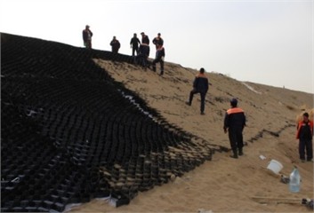
This photograph was taken between November 5-12, 2020, on the Bukhara-Misken railway section, at the Kiyikli-Khizrbobo segment, km 4199, pk 1.
The stability of railway subgrades is particularly critical for lines designed for high-speed and very high-speed passenger traffic. Both domestic and international studies have focused on reinforcing subgrade slopes to ensure structural stability and reliability. In addition to stability, technological reliability and cost-effectiveness are essential considerations.
A methodology for experimental studies was developed to assess various reinforcement solutions using geosynthetic materials. Comprehensive multi-variant experiments were conducted on the Kiyikli-Khizrboho segment (km 4199, pk 1) of the Bukhara-Misken railway line, located in a desert area composed of barchan sands. The railway subgrade embankment at this site ranges from 6 to 10 meters in height. During the experiments, 1,400 m2 of geotextile and 1,200 m2 of three-dimensional geogrid were installed to evaluate their effectiveness.
The slope stability coefficient of the embankment was calculated using the classical formula by Shakhunyants [17]:
where: – Cohesion of dry and moist embankment soils, and moist foundation soils, kPa; – Friction coefficient of dry and moist embankment soils, and moist foundation soil; – Width of the foundation of the -th section (m) for dry and moist embankment soils, and moist foundation soil; – normal component of the weight of the -th slice, kN; ; – restraining component of the weight of the -th slice, kN; ; – driving (shearing) component of the weight of the -th slice, kN; .
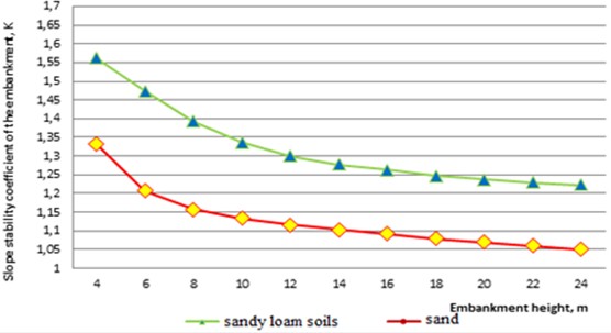
Calculations of the stability coefficient of embankment slopes, using Eq. (1), were performed for various soil types. The graphs showing the variation of the slope stability coefficient for different soils are presented in Fig. 2.
Analysis of the calculation results indicates that the normative value of the slope stability coefficient, 1.2 is achieved in all soils except sandy soils. The following factors influence the values of slope stability coefficients: physico-mechanical properties of the soils: unit weight , internal friction angle , cohesion , etc.; cross-sectional profile of the embankment; embankment height; slope inclination; soil amelioration conditions; influence of water; seismic forces.
The most effective method for increasing the stability of railway embankment slopes is reinforcement with geosynthetic materials. A positive effect is also observed when geosynthetic materials are used to enhance the stability of slopes constructed from barchan sands.
Fig. 2Variation of the embankment slope stability coefficient for different soil types
When reinforcing embankment slopes with geosynthetic materials, the increase in stability is achieved due to the increase in the restraining force . In each -th cell of the geogrid, internal forces develop. According to Newton’s third law, in each -th geogrid cell, the resultant shear force and restraining force are equal to zero, since the geogrid cells filled with soil are anchored. These anchors prevent downward displacement of the geogrids.
As a result, cohesion forces between soil particles develop in each -th geogrid cell, denoted as , along with friction forces :
When calculating the forces acting on each -th geogrid cell, restraining forces from the geogrid, , arise. According to the calculation scheme (Fig. 3), these forces are expressed by the following formula:
where: – cohesion of the soil in the -th geogrid cell, kPa; – friction coefficient of the soil in the -th geogrid cell; – base length of the -th geogrid cell, m; – normal component of the weight of the -th geogrid cell, kN.
When calculating the slope stability coefficient for embankments reinforced with geosynthetic materials, it is necessary to modify Eq. (1) by including the proposed restraining forces and , which account for the forces acting on each -th geogrid and geotextile cell.
After this modification, Eq. (1) takes the following form:
The slope stability coefficient of an embankment constructed from sandy soils and reinforced with geosynthetic materials was calculated using the newly derived Eq. (5), taking into account the restraining forces and .
The values of the restraining forces used in the calculation of the slope stability coefficient for embankments constructed from sandy soils are presented in Table 1.
Table 1Values of restraining forces for embankment slopes constructed from sandy soils and reinforced with geosynthetic materials
Restraining forces | Embankment height, m | |||||||||
6 | 8 | 10 | 12 | 14 | 16 | 18 | 20 | 22 | 24 | |
450.4 | 494.88 | 527.3 | 564.7 | 634.1 | 683.5 | 774.8 | 839.3 | 906.8 | 994.5 | |
111.0 | 118.2 | 125.3 | 132.4 | 139.6 | 146.7 | 153.9 | 161.1 | 168.2 | 175.4 | |
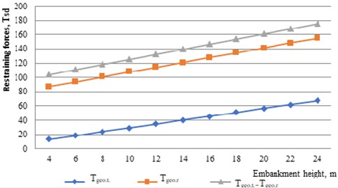
The graph showing the variation of the restraining forces and with embankment height during the installation of geosynthetic materials on the slopes of embankments constructed from sandy soils is presented in Fig. 3.
Fig. 3Variation of restraining forces Tgeo.r and Tgeo.t
The results of the calculations of the slope stability coefficient for embankments constructed from sandy soils, both without reinforcement and with reinforcement using geosynthetic materials, taking into account the restraining forces and , are presented in Table 2.
Table 2Results of the slope stability coefficient calculations for embankments constructed from sandy soils, without reinforcement and with reinforcement using geosynthetic materials
Stability coefficient | Slope stability coefficient at embankment height, m | |||||||||
6 | 8 | 10 | 12 | 14 | 16 | 18 | 20 | 22 | 24 | |
, without reinforcement | 1.207 | 1.158 | 1.134 | 1.116 | 1.103 | 1.092 | 1.083 | 1.075 | 1.068 | 1.061 |
, with reinforcement | 1.491 | 1.392 | 1.337 | 1.299 | 1.273 | 1.251 | 1.234 | 1.222 | 1.215 | 1.211 |
The graphs showing the variation of slope stability coefficients for embankments constructed from sandy soils, both without reinforcement and with reinforcement using geosynthetic materials, taking into account the restraining forces and , are presented in Fig. 4.
The graph showing the variation of slope stability coefficients for embankments in different soils, without reinforcement and with reinforcement using geosynthetic materials in sandy soils, taking into account the restraining forces and , is presented in Fig. 5.
It is advisable to reinforce the slopes of embankments and cuttings of newly constructed roads with water-soluble polymers, which strengthen the soil, particularly sandy soil. This also promotes accelerated vegetation growth, improving the overall appearance of the road and contributing to the development of tourism in the country.
Fig. 4Variation of slope stability coefficients for embankments constructed from sandy soils: 1 – without reinforcement; 2 – with reinforcement using geosynthetic materials
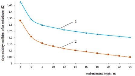
Fig. 5Variation of slope stability coefficients for embankments in different soils: without reinforcement and with reinforcement using geosynthetic materials in sandy soils
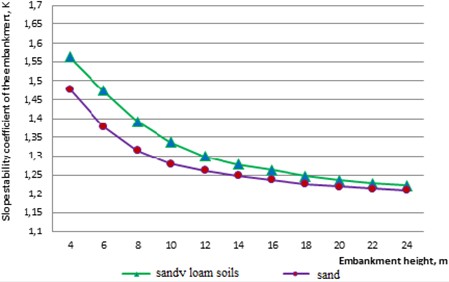
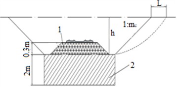
Fig. 6Cross-section of an embankment excavation with geotextile reinforcement – 1, and compacted foundation – 2
4. Conclusions
The volume of earthworks during soil reinforcement is reduced due to the increased steepness of embankment and cutting slopes. This leads to a narrower right-of-way for the railway, which meets modern ecological requirements.
An increase in the restraining force by 18-25 % was observed when reinforcing the slopes of embankments constructed from sandy soils with geosynthetic materials, due to the additional calculated parameters and . As a result, the slope stability coefficient increases by 14-23 % and consistently satisfies the required condition 1.2.
Key findings from the calculations and experiments include:
1) The normative stability threshold \approx 1.2 was achieved for all soils except untreated sandy soils ( \approx 1.1.05).
2) Reinforcement with geosynthetics increased the stability coefficient of sandy soils from 1.05 to 1.35, surpassing the normative requirement.
3) Factors affecting include: soil physico-mechanical properties (unit weight , cohesion , internal friction ), embankment height, slope inclination, cross-sectional profile, water content, soil amelioration, and seismic forces.
4) Graphical analysis (Fig. 2) demonstrates that geosynthetic reinforcement consistently improves stability across all soil types, with the largest effect observed in highly deformable sandy soils.
The results clearly indicate that the most effective approach for improving slope stability is the use of geosynthetic materials. In addition to stability, reinforcement reduces material usage and labor costs, demonstrating both economic and environmental benefits. These outcomes support the implementation of the proposed reinforcement solutions in new construction projects and in the reconstruction or widening of existing embankments, particularly in desert areas with barchan sands.
The experimental and calculated data confirm that the geosynthetic reinforcement system ensures structural integrity, meets normative stability requirements, and provides a practical, cost-effective solution for high-speed railway subgrades under challenging geotechnical and seismic conditions.
References
-
A. Abdujabarov, P. Begmatov, M. Mekhmonov, and F. Eshonov, “Strengthening of the railroad track for high-speed traffic on the Bukhara-Misken section,” E3S Web of Conferences, Vol. 515, p. 02014, Apr. 2024, https://doi.org/10.1051/e3sconf/202451502014
-
A. Abdujabarov, F. Eshonov, P. Begmatov, M. Mekhmonov, and M. Khamidov, “Calculation of the seismic stress state of the ground-gallery system,” in AIP Conference Proceedings, Vol. 3045, No. 1, p. 030098, Jan. 2024, https://doi.org/10.1063/5.0197333
-
M. Muzaffarova and M. Mirakhmedov, “Dilatation of the method of fixation of moveable sands,” in AIP Conference Proceedings, Vol. 2612, p. 040007, 2023, https://doi.org/10.1063/5.0135327
-
K. S. Lesov and M. K. Kenjaliyev, “Organizational and technological parameters during the construction of the bukhara-misken railway line,” in AIP Conference Proceedings, Vol. 2471, p. 030026, Jan. 2022, https://doi.org/10.1063/5.0089621
-
K. S. Lesov, Z. Z. Ergashev, M. K. Kenjaliyev, and S. A. Tadjibaev, “Quantitative characteristics of construction and reconstruction of railway sections in Uzbekistan,” E3S Web of Conferences, Vol. 401, p. 03024, Jul. 2023, https://doi.org/10.1051/e3sconf/202340103024
-
I. P. Kiselev, “High-speed railway transport and its development prospects worldwide,” Transport of the Russian Federation, Vol. 5, No. 42, pp. 44–51, 2012.
-
M. Muzaffarova and M. Mirkhanova, “Investigations of damage to the under-rail base on the main routes JSC “Uzbekistan Temir Yullari,” E3S Web of Conferences, Vol. 401, p. 05034, 2023, https://doi.org/10.1051/e3sconf/202340105034
-
G. A. Khalfin and K. Umarov, “The work of intermediate rail fasteners on mountain sections of railways,” in International Scientific Conference Construction Mechanics, Hydraulics and Water Resources Engineering, CONMECHYDRO 2021 ASTashkent7 September 2021, Sep. 2021.
-
I. N. Zhuravlev, “Assessment of the influence of geomaterials on the stress-strain state of railway embankments,” St. Petersburg, 2005.
-
P. V. Dyba, “Increasing the bearing capacity of loaded soil masses by reinforcement with geosynthetic materials,” St. Petersburg, 2011.
-
A. D. Koshchin, “Technology for reinforcing slopes of earth structures with cut geocell constructions,” Ufa, 1998.
-
V. M. Ermakov, J. I. S. Blazhko, and M. V. Bushuev, “Efficiency of geotextile installation,” Way and Track Economy, No. 3, pp. 5–8, 2008.
-
A. L. Lanis, “Methods of embankment reinforcement by grouting,” Izvestiya TransSib, Vol. 3, No. 27, pp. 117–124, 2016.
-
K. S. Lesov, A. K. Mavlanov, U. K. Abduraimov, and M. K. Kenzhaliev, “Development of design solutions for ensuring the stability of sandy soil embankments,” in Materials of the Republican Scientific and Technical Conference with Participation of Foreign Scientists “Resource-Saving Technologies in Railway Transport, Vol. 15, No. 15, pp. 78–81, 2020.
-
S. A. Chelobitchenko, “Methodology for calculation and design-technical solutions of embankments reinforced with three-dimensional geogrids on permafrost soils,” St. Petersburg, 2007.
-
K. S. Lesov, S. A. Tadzhibaev, A. M. Mavlanov, and M. K. Kenzhaliev, “Calculation of embankment stability and slope reinforcement of railway embankments using geosynthetic materials,” Transport of the Silk Road (International Scientific Electronic Journal), No. 1, pp. 78–83, 2021.
-
“Program and methodology for experimental studies on reinforcing slopes of railway embankments,” TashIIT, Tashkent, Tashkent institute of railway engineers, 2020.
About this article

The authors have not disclosed any funding.
The datasets generated during and/or analyzed during the current study are available from the corresponding author on reasonable request.
The authors declare that they have no conflict of interest.
