Abstract
The paper presents the results of comparative numerical analyses of design alternatives for the permanent lining of Hydraulic Tunnel No. 3 at the Rogun Hydropower Plant in the zone of intersection with the Ionakhsh tectonic fault. Three tunnel lining design options were considered. The comparison of structural alternatives was carried out based on the ability of the linings to accommodate ground movements within the Ionakhsh fault zone, where ongoing tectonic activity has been recorded. The behavior of the lining under fault-induced displacements was investigated using a three-dimensional finite element method, taking into account nonlinear contact deformations associated with shear and opening along the lining deformation joints, as well as at the interface between the tunnel and the surrounding rock mass.
Highlights
- Comparison of Design Options: Three structural alternatives for the Rogun HPP Hydraulic Tunnel №3 lining were evaluated using 3D finite element analysis to determine their capacity to accommodate ground movements within the active Ionakhsh tectonic fault zone.
- Optimized Structural Performance: All three options can withstand design displacements, but Option №1 is the most economical, while Option №2 is the stiffest. Adjusting joint orientation is recommended to reduce tensile stresses and excavation volumes.
- Numerical Simulation Results: 3D FEM modeling revealed that fault-induced displacements of 50–100 mm cause significant stress concentration and non-uniform joint opening, particularly in the hanging wall, due to the misalignment of joints with the fault strike.
1. Introduction
Three tunnel lining design options for a hydraulic tunnel in the zone of intersection with the Ionakhsh tectonic fault are considered in the paper:
– Option 1, developed in the original design by Sredazgidroproekt.
– Option 2 (Tono Energy International, Iran).
– Option 3 (Electroconsult, Italy).
The comparison of the lining design alternatives was performed based on their ability to accommodate displacements along the Ionakhsh fault system, where contemporary tectonic movements are observed [1]. The response of the tunnel lining to fault-induced displacements was investigated using a three-dimensional finite element model, incorporating nonlinear contact shear deformations along the lining deformation joints and at the tunnel-rock mass interface [3].
Tectonic faults are geological structures formed as a result of crustal movements. It is well known that the Earth’s crust consists of large and small plates, referred to as lithospheric plates. When these plates move, they may collide, diverge, or shift relative to each other in different directions. Such movements lead to the formation of various geological structures, including faults.
Faults are often associated with earthquakes and crustal deformation. As plates move along fault planes, stress develops and accumulates, causing deformation of rocks and soils. This process may occur over long geological periods and can result in the formation of mountain ranges, depressions, and other geological features [5].
2. Geological setting and research methodology
The assessment of permanent lining design options is carried out using Hydraulic Tunnel No. 3 of the Rogun Hydropower Plant as a case study. The hydraulic tunnel sequentially intersects the feathering zone of tectonic lens fragmentation and the displacement plane of the Ionakhsh fault. These discontinuities separate tectonic blocks that differ significantly in geological structure [4].
The tectonic block partially located between the inlet portal and the Ionakhsh fault consists of terrigenous deposits with gypsum admixtures and Cretaceous carbonate formations composing the Kirbich synclinal fold.
Numerical Simulation Methodology. To evaluate the structural integrity, a three-dimensional finite element method (FEM) was employed. The numerical model accounts for the non-linear interaction between the reinforced concrete lining and the surrounding rock mass. Contact elements were used to simulate the shear and opening behaviors of the deformation joints under a design fault displacement of 50-100 mm, corresponding to a 10-20 year service life.
3. Modeling of the stress-strain state of the contour of mining
The pressure hydraulic tunnel has a total length of 1.8 km. Along the alignment of Hydraulic Tunnel No. 3 of the Rogun Hydropower Plant, several basic lining types were designed, with a characteristic clear span of 14.0-14.5 m.
Numerical Simulation Framework. The numerical analysis was performed using the ANSYS Mechanical APDL software suite. The rock mass and the thickened lining sections were discretized using high-order 3D 10-node tetrahedral structural solids (SOLID187), providing high accuracy for irregular geometries. To simulate the behavior of deformation joints and the tunnel-rock interface, a non-linear contact model was implemented using TARGE170 (target surface) and CONTA174 (contact surface) elements. The Coulomb friction model was applied at these interfaces to capture potential sliding and opening under tectonic displacement. The iterative solution was based on the Newton-Raphson method to ensure convergence of the non-linear kinematic equations.
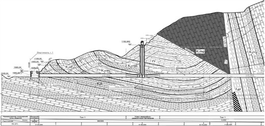
According to the design, Hydraulic Tunnel No. 3 at chainage 8+28 crosses the Ionakhsh fault approximately 400 m downstream of the maintenance gates [8]. The fault is located at the boundary between limestone and argillite rock masses. Contemporary tectonic movements have been recorded along this fault; therefore, a special lining structure is designed at the fault crossing section [10]. Currently, based on new data obtained during tunnel excavation, the engineering-geological cross-section has been significantly refined compared with the 2012 design, as shown in Fig. 1.
Fig. 1Engineering-geological cross-section. Source: Created by the authors based on Rogun HPP geological surveys, 2024
According to the updated data, the thickness of the crushed zone of the tectonic lens fault has been reduced from 35 m to 10 m, while the thickness of the fault gouge has decreased to 1 m. Ongoing tectonic movements are observed along the fault, with an average displacement rate of up to 5 mm per year. The displacement direction is as follows: the footwall moves downward, while the hanging wall moves upward along the fault plane.
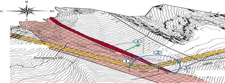
In the intersection zone with the transport tunnel, the fault dip angle is 85°, and the strike angle is 45° (measured clockwise from north). The strike of Tunnel ST-3 at the fault crossing location is 155°. Accordingly, the angle between Tunnel ST-3 and the fault strike is 70°, as illustrated in Fig. 1.
At the intersection of Hydraulic Tunnel No. 3 with the transport tunnel, the fault dip angle is 85°, and the strike angle is 45° (measured clockwise from north). The strike of Hydraulic Tunnel No. 3 at the fault crossing location is 155°. Accordingly, the angle between the hydraulic tunnel axis and the fault strike is 70°, as shown in Fig. 2.
In the numerical analyses, the self-weight of the rock mass, including the fault infill material and reinforced concrete linings, was not considered. Therefore, the calculated displacements and stresses are caused solely by the kinematic displacement of the hanging wall block along the fault plane, referred to as “additional displacements and stresses”.
In addition, reinforcement connections between lining segments were not considered in the stress-strain analysis of the three variants, due to the unconventional structural behavior [2], whereby interaction forces develop only after a certain displacement of reinforcement within the cavity of the kinematic problem.
Hydraulic Tunnel No. 3 is considered a temporary structure; assuming a service life of 10-20 years, the design fault displacement is estimated to be 50-100 mm.
Fig. 2Plan of the intersection of Tunnel No. 3 of the Rogun HPP with the Ionakhsh Fault: 1 – strike angle of the Ionakhsh Fault (45°, measured clockwise from north); 2, 3 – angles between the tunnel axis and the fault strike (110° and 70°); 4 – fault dip direction
In the numerical analyses and presentation of results, a global coordinate system was used: the -axis is directed along the tunnel towards the downstream side, the -axis is oriented vertically upward, and the -axis is perpendicular to the flow. The origin of the coordinate system is at the ±0.000 level. The orientation of the coordinate axes in three-dimensional space is indicated in the figures, usually in the lower-left corner.
Option No. 1. According to the designs by Sredazgidroproekt, a tunnel lining configuration was developed for the intersection with Fault No. 35, which has a significantly smaller thickness than the Ionakhsh Fault [7]. Therefore, the tunnel lining design was adjusted for the conditions of the Ionakhsh Fault, which has a crushing zone thickness of 10 m and a friction clay layer thickness of 1 m. Parameters from the lining designs of Tunnel Options No. 2 and No. 3 in the Ionakhsh Fault zone were also taken into account.
The proposed design solution consists of thickening the monolithic reinforced concrete lining to 1.8 m in the section intersecting the tectonic disturbance, with the lining divided into 7 segments, each 3.0 m long. Where the thickened lining adjoins the standard lining, two additional transition segments of 1.5 m length are provided. Thus, eight deformation joints, each 30 mm wide with reinforcement connectors, are created in the fault intersection zone. The total length of the lining, including the transition segments, is 24.0 m.
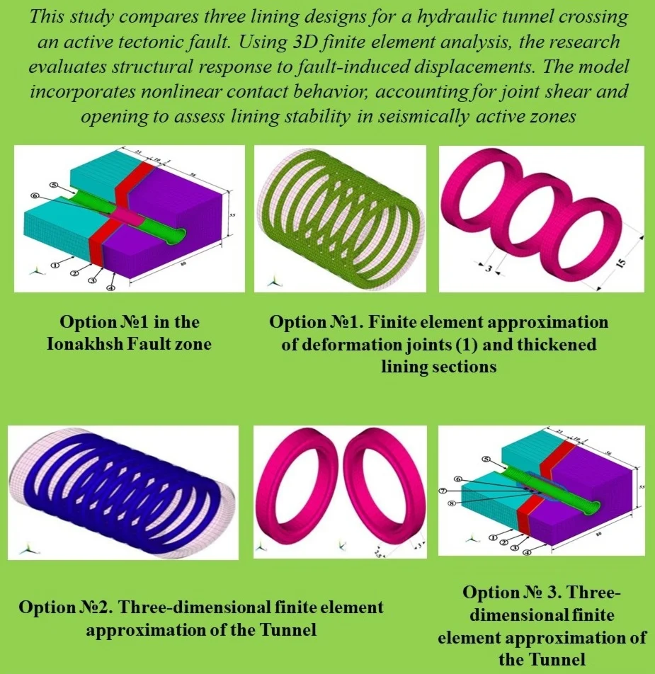
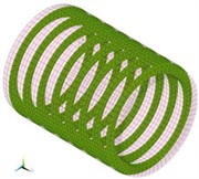
The developed three-dimensional finite element model of the hydraulic tunnel with lining according to Option No. 1 is shown in Fig. 3. The dimensions of the rock block enclosing the tunnel are 90 m along the tunnel length, 55 m in height, and 80 m in width. The model consists of 123.256 finite elements (FEs), including solid FEs of type SOLID for modeling the rock mass (90.272 FEs) and the thickened lining sections (12.090 FEs), shell FEs of type SHELL for modeling the standard tunnel lining (4.092 FEs), and special contact elements of type CONTA/TARGE for modeling contact interactions between lining segments (4.960 FEs) and between the lining and the rock mass (11.842 FEs).
Fig. 3Option No. 1 in the Ionakhsh Fault zone: 1 – sandstone; 2 – crushing zone; 3 – friction clay; 4 – argillites; 5 – standard tunnel lining; 6 – lining in the compensation section
Displacement analysis shows that a 10 mm fault displacement causes significant movements across two deformation joints, while fault displacements of 50 mm and 100 mm affect four joints.
It is notable that the largest displacements and stresses are concentrated in the hanging side of the fault and are localized within two rings, whereas the four rings on the footwall side remain largely inactive. The uneven distribution of forces among the rings and the non-uniform opening of the deformation joints – which considerably complicate the performance of the structure – are associated with the poor alignment of the deformation joints relative to the direction of fault displacement.
Fig. 4Option No. 1: a) finite element approximation of deformation joints and b) thickened lining sections
a)
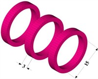
b)
Option No. 2. The design solution also involves thickening the standard monolithic reinforced concrete lining at the section intersecting the fault [9]. In Option No. 2, the lining thickness is set at 2.5 m, with the tunnel length divided into 8 segments, each 3.0 m long. At the locations where the thickened lining adjoins the standard lining, two additional transition segments, each 4.0 m long, are provided. Thus, a total of nine deformation joints, each 30 mm wide with grooves and reinforcement connectors, are created in the fault intersection zone. The total length of the lining, including the transition segments, is 32.0 m.
It should be noted that the main difference between Option No. 2 and the previous Option No. 1 lies in the structural design of the deformation joints, specifically:
1) The deformation joints are designed with grooves.
2) The reinforcement connectors are arranged in two rows.
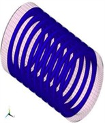
The developed three-dimensional finite element model of the hydraulic tunnel with lining according to Option No. 2 is presented in Fig. 5. The dimensions of the rock block enclosing the tunnel are the same as those in Option No. 1. The model consists of 112.905 finite elements (FEs), including solid FEs of type SOLID for modeling the rock mass (54.240 FEs) and the thickened lining sections with grooved joints (33.600 FEs), shell FEs of type SHELL for modeling the standard tunnel lining (1.800 FEs), and special contact elements of type CONTA/TARGE (Fig. 5). To simulate contact interactions (13.860 FEs), the grooved deformation joints with an initial opening of 30 mm are reproduced; 90.345 FEs are at the “concrete–rock mass” interface.
Fig. 5Option No. 2. Three-dimensional finite element approximation of the Tunnel No. 3 – enclosing rock mass system in the Ionakhsh Fault zone: 1 – sandstone; 2 – crushing zone; 3 – friction clay; 4 – argillites; 5 – standard tunnel lining; 6 – thickened lining with grooved joints
a)
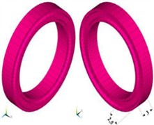
b)
The results show that the largest displacements and stresses are concentrated in the hanging wall of the fault and are localized in four thickened rings. It should be noted that the four thickened rings and the transition ring on the footwall side remain largely inactive under fault displacement. Due to the grooves, the structure is stiffer compared to Option No. 1, engaging a larger number of rings; however, tensile stresses in both directions are increased.
As in Option No. 1, the uneven distribution of forces among the rings and the non-uniform opening of the deformation joints – which significantly complicate the structural performance – are associated with the misalignment of the deformation joints relative to the fault displacement direction.
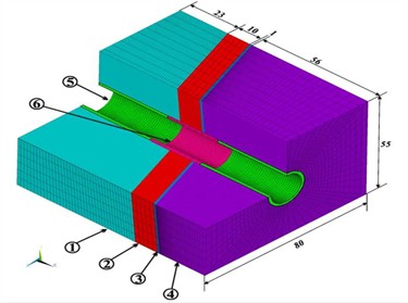
Option No. 3. The design solution consists of a three-layer composite lining. The outer reinforced concrete lining, 3.5 m thick, is segmented by deformation joints at 5.0 m intervals. The middle layer, 1.5 m thick, is intended by the designers to serve a damping function and is made of cellular concrete. The inner reinforced concrete lining, 0.5 m thick, is continuous along the entire fault intersection zone. Thus, the total thickness of the three-layer lining is 5.5 m.
According to Fig. 6, five standard segments, each 5 m long, and four transition segments (two on each side) of the same length are proposed. Therefore, six deformation joints are created within the standard segment zone (in the thickened three-layer lining), and two deformation joints are created within the transition segment zone (in the thickened single-layer lining), resulting in a total of eight deformation joints. The total length of the lining, including the transition segments, is 45 m.
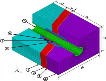
The developed three-dimensional finite element model of the hydraulic tunnel with lining according to Option No. 3 is shown in Fig. 6. The dimensions of the rock block enclosing the tunnel are the same as in Option No. 1. The model consists of 94.364 finite elements (FEs), including solid FEs of type SOLID for modeling the enclosing rock mass (48.112 FEs), thickened sections of the outer lining (14.260 FEs), the damping layer made of cellular concrete (6,386 FEs), shell FEs of type SHELL for modeling the standard tunnel lining and the inner lining (4.526 FEs), and special contact elements of type CONTA/TARGE. For simulating contact interactions, 4.960 FEs reproduce deformation joints in the outer lining with an initial opening of 30 mm; 10.292 FEs represent the “concrete-rock mass” interface, and 5.828 FEs represent the interface between cellular concrete and reinforced concrete.
Notably, the largest displacements and stresses are concentrated in the hanging wall of the fault, primarily within the main thickened ring; the four thickened rings and the transition rings on the footwall side remain largely inactive under fault displacement.
Stresses in the three-layer lining are distributed unevenly. In the outer lining, the highest tensile stresses occur in the circumferential direction, reaching +26.0 MPa. In the inner reinforced concrete lining, the maximum tensile stresses reach +24.6 MPa. In the damping layer made of cellular concrete, the stress range is from -3.25 to +1.75 MPa.
As in the previous options, these structural performance challenges are associated with the misalignment of the deformation joints relative to the direction of fault displacement.
Fig. 6Option No. 3. Three-dimensional finite element approximation of the Tunnel No. 3 – enclosing rock mass system in the Ionakhsh Fault zone: 1 – sandstone; 2 – crushing zone; 3 – friction clay; 4 – argillites; 5 – standard tunnel lining; 6 – segmented outer reinforced concrete lining; 7 – damping layer of cellular concrete; 8 – continuous inner reinforced concrete lining
4. Conclusions
1) Based on mathematical modeling of the lining behavior under fault displacement, a comparison was performed for three design options of the permanent lining of Hydraulic Tunnel No. 3 in the Ionakhsh Fault intersection zone.
2) The main drawback of all lining design options in the Ionakhsh Fault zone is that the orientation of the planned deformation joints forms a large angle with the fault displacement direction. From a kinematic perspective, the joint orientation is unfavorable, leading to ineffective performance of the deformation joints, significant tensile stresses in the lining sections, and increased volumes of underground work.
3) Analysis of the numerical study results indicates that all lining options can theoretically be used in the Ionakhsh Fault zone for fault displacements in the range of 50-100 mm; however, the following key features of each option should be considered:
– Option No. 1 – the most economical in terms of material consumption, but the efficiency of the structure is limited: displacement along the fault is distributed over only four of the eight designed deformation joints, and significant circumferential tensile stresses (up to +39.0 MPa) require substantial reinforcement of the sections.
– Option No. 2 – the stiffest design due to the grooved deformation joints; as a result, tensile stresses are the highest (+44.3 MPa in the circumferential direction and +23.8 MPa in the axial direction), requiring the greatest amount of reinforcement.
– Option No. 3 – the most material-intensive. Implementation requires excavation 45 m in length and 25 m in diameter to intersect the Ionakhsh Fault with a thickness of 11 m. Additional tensile stresses in the outer lining can reach +26.0 MPa at 3.5 m thickness, and in the inner lining up to +24.6 MPa at 0.5 m thickness; these stresses may increase after the failure of the damping layer.
4) The selection of the preferred option should be based on economic comparison, as the options differ significantly in terms of rock excavation volumes, concrete and reinforcement consumption, constructability, and ease of execution.
5) To refine the lining design, it is recommended to determine the maximum expected fault displacement considering the design service life of the tunnel and operational requirements for joint sealing.
6) A significant reduction in rock excavation, concrete, and reinforcement consumption can be achieved by modifying the lining design of Tunnel No. 3 in the Ionakhsh Fault zone through adjustment of the orientation of the deformation joints [6].
References
-
C. C. Li, “Disturbance of mining operations to a deep underground workshop,” Tunnelling and Underground Space Technology, Vol. 21, No. 1, pp. 1–8, Jan. 2006, https://doi.org/10.1016/j.tust.2005.04.001
-
M. H. Baziar, A. Nabizadeh, R. Mehrabi, A. Ghalandarzadeh, and C. J. Lee, “Evaluation of integrated segment tunnel lining under normal fault movement using 1g physical modeling,” Environmental Earth Sciences, Vol. 71, No. 12, pp. 5209–5223, 2014.
-
R. Jankowski, “Experimental study on earthquake‐induced pounding between structural elements made of different building materials,” Earthquake Engineering and Structural Dynamics, Vol. 39, No. 3, pp. 343–354, Jul. 2009, https://doi.org/10.1002/eqe.941
-
M. G. Kalibhat and A. Upadhyay, “Numerical modeling of continuous steel concrete composite girders considering cracking of concrete,” Structures, Vol. 27, pp. 1313–1323, Oct. 2020, https://doi.org/10.1016/j.istruc.2020.07.031
-
G. Russo and A. Grimaldi, “Advanced design of deep tunnels in complex tectonic environments,” Rock Mechanics and Rock Engineering, Vol. 52, No. 12, pp. 5195–5210, 2019.
-
N. M. Khasanov, “Methods for conducting cementation works in hydraulic construction,” Bulletin of TNU, No. 3, pp. 85–93, 2022.
-
“SP 14.13330.2018. Construction in Seismic Regions,” Minstroy of Russia, Moscow, 2018.
-
“Rogun HPP. Construction Tunnel No 3,” Hydroproject Institute, Moscow, 2012.
-
“Rogun HPP. Technical Drawings RG-CT3-ROC-004-R3,” Tono Energy International, Tehran, 2014.
-
M. Huang and C. Song, “Upper-bound stability analysis of a plane strain heading in non-homogeneous clay,” Tunnelling and Underground Space Technology, Vol. 38, pp. 213–223, Sep. 2013, https://doi.org/10.1016/j.tust.2013.07.012
About this article

The authors have not disclosed any funding.
The datasets generated during and/or analyzed during the current study are available from the corresponding author on reasonable request.
The authors declare that they have no conflict of interest.
