Abstract
The article presents the deformations occurring at the transition section and damages of different degrees of track structure elements due to different stiffness in the zone of conjunction of the bridge bank piers with the earth bed at high-speed railway sections. The reduction of the coefficient of active pressure arising laterally by means of transferring a part of active pressure of the earth bed to the foundation as a result of reinforcement of embankment with reinforced concrete piles at the places of conjunction of the bridge bank supports and the earth bed of the high-speed railroad section in the seismically active zone is given. The elastic deformability with reduction of impact on the bridge shore support in different seismic activity as a result of reinforced concrete piles reinforcement of embankment at the transition section of the bridge with the earth bed has been determined. And also graphs of increase of angle of internal friction of soil and decrease of pressure coefficient under the action of seismic and vibrodynamic forces are given. Methods for determining the distribution of seismic and vibrodynamic forces arising from high-speed railways on embankments constructed from different soils and geometric dimensions of reinforced concrete piles to reduce them on the basis of graphs are given.
Highlights
- The photograph taken by the second author on August 25, 2025, depicts the process of examining issues in the railway superst.
- Scheme of deformation occurrence due to reduced embankment rigidity in the transition zone from the roadbed to the bridge.
- Reinforcement of the embankment part of the earth bed of the bridge shore abutment with piles 1-shore bridge abutment; 2-reinforced concrete piles; L-length of piles.
1. Introduction
Seismic inertial forces acting on the railway track is determined in accordance with the requirement of SNiP Uzbekistan (SHNK 2.01.20-16) according to the known formula depending on the weight of the railway track, as well as the coefficient of seismicity and dynamism, which in real conditions need to be specified.
It should be noted that given the seismicity of the area, the number of in-depth special studies devoted to the design of railways is very small. When designing the Turkestan-Siberian railway they faced big problems on seismic resistance. These problems were partially solved by researches of Prof. V.O. Tshokher in 1929 and reflected in the edition of SNiP II-A, 12-69. The question of designing the earth bed taking into account the initial seismicity became more and more acute during the design of the Baikal-Amur Mainline in 1968 [1], [2], [3], [4], [5].
The issue of generalization of all the studies conducted on the design of railways taking into account the degree of seismicity of the area was assigned to the Moscow Research Institute of Transport Construction (TsNIIS) and the laboratory “Subgrade”, the main executors were appointed F. I. Tselikov and E. A. Yakovleva. F. I. Tselikov and E. A. Yakovleva noted that experimental studies on earthquake resistance of the earth bed using a seismic platform under the guidance of Academician M.T. Urazbayev at the Institute of Mechanics and Earthquake Resistance of Structures of the Academy of Sciences of the Republic of Uzbekistan were carried out and the only results were published [6], [7].
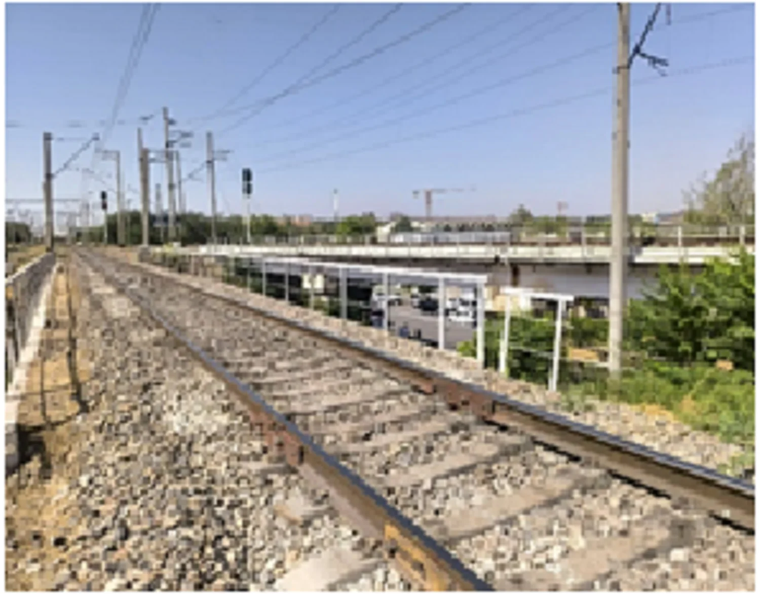
Numerous studies of the increased damageability of bridge shore piers during operation and especially under the action of seismic effects, as well as from high-speed train traffic, have revealed a number of causes that have affected the deformation of the structure to varying degrees. At the transition section, various defects appear in the elements of the upper track structure due to deformation of the earth bed (Fig. 1).
Fig. 1In the transition section, increased vibration of the road's upper structure occurs due to the deformation of the embankment soil, leading to the crushing of ballast materials. The photograph taken by the second author on August 25, 2025, depicts the process of examining issues in the railway superstructure elements at the junction zone between the earthwork and the bridge
The impact of active soil pressure on the shore support, which increases dramatically with increasing traffic speed and seismic effects during an earthquake [8].
2. Materials and methods
The dynamic stiffness of the subgrade, which is interrupted at the bridge shore abutment, is significantly reduced and depends on the stiffness of the bridge span structure and the interface with the bridge abutment [9-12].
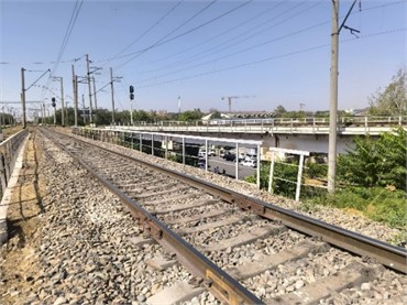
There are various deformations resulting from the increase of amplitude-frequency characteristics in the soils of the railway subgrade due to seismic forces. Under the action of seismic forces, the external forces increase significantly. Increased oscillatory motion of the subgrade leads to changes in the condition of the elements of the track top structure. Different deformations appear as a result of the increase in the active pressure of the subgrade soil under the action of seismic and vibrodynamic forces at the approaches to bridges (Fig. 2).
Fig. 2Scheme of deformation occurrence due to reduced embankment rigidity in the transition zone from the roadbed to the bridge
Analyses show that such deformations during the construction of embankments on approaches to railway bridges will depend primarily on a whole complex of objective and subjective factors related to insufficient soil compaction, as well as changes in the moisture regime during the operation of railways. The active soil pressure affecting the bridge shore support will increase significantly due to seismic forces. As a result, the stability of the bridge will be reduced [13], [14].
3. Results and discussion
Various design solutions have been developed to reduce the impact of active soil pressure on the shore support of the railway bridge at the transition sections. The reinforcement of embankments with reinforced concrete piles at transition sections mainly serves to transfer the external load from the train from the weak soil to the active part of the soil with higher density.
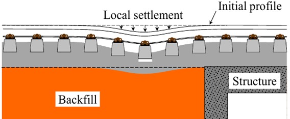
Reinforcement of the embankment in front of the bridge abutment with piles reduces the active soil pressure on the structure, part of the impact loads from moving traffic is transferred directly to the base soil. When piles are driven, the soil of the embankment is additionally compacted and this leads to a more uniform distribution of stresses in the cross-section of the structure.
Fig. 3Reinforcement of the embankment part of the earth bed of the bridge shore abutment with piles 1 – shore bridge abutment; 2 – reinforced concrete piles; L – length of piles
The use of piles to reinforce the embankment of the subgrade allows to increase the stability of the entire structure in a possible earthquake, because it is a relatively flexible reinforcement that allows deformation of the embankment soil without failure, which is described in more detail in.
The most effective reinforced concrete piles are I-beam piles, which are much lighter than rectangular piles and have a large area of contact with the soil. For single-track railroads it is enough -2 piles, for double-track railroads-3 piles.
Under the action of seismic and vibrodynamic forces there is a significant increase in vibrations in the earth bed, erected from weak soils. As a result of driving reinforced concrete piles into the embankment at an angle to the vertical, it is possible to reduce the amplitudes of vibrations and increase the dynamic stiffness of soils in the subgrade. As a result, the reliable operation of the earth bed during the established period is ensured.
We calculate the distance between reinforced concrete piles driven into the ground in order to increase the dynamic stiffness of soils on the approaches to bridges at the height of the embankment 6 m on barchan sands: the width of the main area of the earth bed on the I track sections is 7.6 m, the width of the main area on the II track sections is 11.7 m (ShNK 2.05.01-19. Railways of 1520 mm gauge. Design standards):
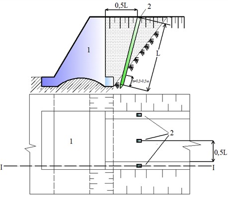
where, – distance between reinforced concrete piles, m; – width of the main site, 7.6 m; – height of the embankment, 6 m; – dynamic coefficient taking into account soil properties, – for barchan sands, 40; – coefficient that takes into account the speed of train traffic: at speeds up to 40 km/h; 1.0; at speed up to 60 km/hour; 0.95; at speed up to 80 km/hour; 0.90; at speed up to 120 km/hour; 0.85; at speed up to 160 km/hour; 0.80; at speed up to 200 km/hour; 0.78; – pile slope angle, it is advisable within the limits -20°-40°; 20; – length of reinforced concrete piles, m. We calculate the length of reinforced concrete piles by geometric method (Fig. 4):
it follows ; m
The calculated distances between reinforced concrete piles driven into the embankment constructed from barchan sands are given in Table 1.
Fig. 4Scheme for determining the length of reinforced concrete pile: 1 – railroad bed, 2 – reinforced concrete pile
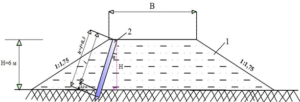
Table 1Distance between reinforced concrete piles driven into embankments on barchan sands
On the I track section embankment height 6 m, width of the main platform 7.6 m | On the II track section embankment height 6 m, width of the main platform 11.7 m | ||
13.9 m | 1.0 | 29.5 m | 1.0 |
13.3 m | 0.95 | 28.2 m | 0.95 |
12.7 m | 0.90 | 26.9 m | 0.90 |
12.1 m | 0.85 | 25.5 m | 0.85 |
11.6 m | 0.80 | 24.1 m | 0.80 |
11.4 m | 0.78 | 23.6 m | 0.78 |
The calculated distances between reinforced concrete piles driven into embankments made of clay soils are presented in Table 2.
Table 2Distance between reinforced concrete piles driven into the embankment in clay soils
On the I track section embankment height 10 m, width of the main platform 7.6 m | On the II track section embankment height 10 m, width of the main platform 11.7 m | ||
19.9 m | 1.0 | 41.9 m | 1.0 |
19.1 m | 0.95 | 40.1 m | 0.95 |
18.3 m | 0.90 | 38.1 m | 0.90 |
17.5 m | 0.85 | 36.2 m | 0.85 |
16.7 m | 0.80 | 34.3 m | 0.80 |
16.4 m | 0.78 | 33.6 m | 0.78 |
The shore support of a railroad bridge must absorb the active pressure () of the ground arising under the action of vibrational and seismic forces from the rolling stock, as well as ensure the safe operation of the structure. The equidistance of the design seismic horizontal ground pressure is determined by the following formula:
where – specific gravity of embankment soil (kN/m3); – design width along the rear surfaces of the pile where seismic ground pressure is distributed, (m); – height from the bottom of the embankment foundation slabs to the bottom of railroad bridge sleepers, m; – coefficient of lateral pressure of embankment soils under seismic action.
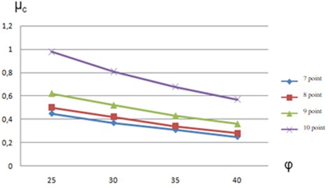
The lateral pressure coefficient of the sandy soil embankment shown in Fig. 5 can be determined as a function of the standard angle of internal friction φ and the design seismic force.
Fig. 5Graph of dependence of lateral pressure coefficient on soil properties at different earthquake intensities without pile driving at transition sections of high-speed railways
The equidistance of the design seismic horizontal ground pressure at the transition sections of high-speed railways after pile driving is determined by the following formula:
where – specific gravity of soil after pile driving in the embankment, (kN/m3); – design width along the rear surfaces of the pile where seismic ground pressure is distributed, (m); – height from the bottom of the embankment foundation slabs to the bottom of railway bridge sleepers, m; – coefficient of lateral pressure of embankment soils under seismic action after pile driving into the embankment.
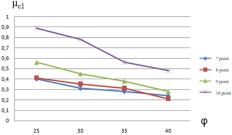
The active ground pressure acting on the shore support of a railroad bridge can be reduced by pile driving, which also results in a significant reduction of the seismic force (Fig. 6).
Fig. 6Graph of dependence of lateral pressure coefficient on soil properties at different earthquake intensities after driving reinforced concrete piles at transition sections of high-speed railways
An increase in the active pressure of the embankment soil due to seismic and vibrodynamic vibrations is observed in the area where the earthwork and the bridge connect. As a result, vertical oscillations occur in the transition section. These vertical oscillations cause various deformations in the road superstructure. To reduce these deformations, reinforcement of the embankment in the transition section with reinforced concrete piles is required.
4. Conclusions
1) An elastic deformed structural solution is developed to prevent vertical irregularities of track elements of high-speed railways on approaches to bridges in a seismic active region.
2) By reinforcing the embankment designed in a seismic active region with reinforced concrete piles on approaches to high-speed railway bridges, significantly reducing the active soil pressure on the structure, a part of the impact forces from the rolling stock is transferred to the base soil.
3) At an internal friction angle of 300 and intensity of 7 points, the experimental study determined the reduction of the lateral pressure coefficient of high-speed railway embankments up to 19 %.
References
-
K. S. Lesov, M. M. Rasulmukhamedov, A. K. Mavlanov, and M. K. Kenjaliyev, “Tension of ground pressure on the foundations of railway catenary supports,” in E3S Web of Conferences, Vol. 401, p. 03035, Jul. 2023, https://doi.org/10.1051/e3sconf/202340103035
-
K. Lesov, M. Kenjaliyev, A. Mavlanov, and S. Tadjibaev, “Stability of the embankment of fine sand reinforced with geosynthetic materials,” in E3S Web of Conferences, Vol. 264, p. 02011, Jun. 2021, https://doi.org/10.1051/e3sconf/202126402011
-
G.-A. Khalfin, K. Umarov, I. Purtseladze, and M. Yembergenov, “System for determining state of continuous welded track,” in E3S Web of Conferences, Vol. 401, p. 02050, Jul. 2023, https://doi.org/10.1051/e3sconf/202340102050
-
X. Guo, J. Liu, and R. Cui, “Research on train-induced vibration of high-speed railway station with different structural forms,” Materials, Vol. 17, No. 17, p. 4387, Sep. 2024, https://doi.org/10.3390/ma17174387
-
E. Fortunato, A. Paixão, and R. Calçada, “Railway track transition zones: design, construction, monitoring and numerical modelling,” International Journal of Railway Technology, Vol. 2, No. 4, pp. 33–58, Jan. 2013, https://doi.org/10.4203/ijrt.2.4.3
-
A. Abdujabarov, M. Mekhmonov, P. Begmatov, F. Eshonov, and M. Khamidov, “Consideration of the environmental impact on the seismic inertial forces of the railway track in difficult conditions,” in Problems in the Textile and Light Industry in the Context of Integration of Science and Industry and Ways to Solve Them: PTLICISIWS-2, Vol. 3045, p. 030097, Jan. 2024, https://doi.org/10.1063/5.0197332
-
A. Abdujabarov, F. Eshonov, P. Begmatov, M. Mekhmonov, and M. Khamidov, “Calculation of the seismic stress state of the ground-gallery system,” in Problems in the Textile and Light Industry in the Context of Integration of Science and Industry and Ways to Solve Them: PTLICISIWS-2, Vol. 3045, p. 030098, Jan. 2024, https://doi.org/10.1063/5.0197333
-
M. Mekhmonov, S. Makhamadjonov, and A. Uralov, “Efficiency of reinforcement of transition sections on the railroad by the developed constructions,” in E3S Web of Conferences, Vol. 508, No. 9, p. 08017, Apr. 2024, https://doi.org/10.1051/e3sconf/202450808017
-
M. Mekhmonov, S. Makhamadjonov, and A. Uralov, “Stabilization of embankments and coastal bridges with reinforced concrete piles,” in E3S Web of Conferences, Vol. 508, No. 9, p. 08018, Apr. 2024, https://doi.org/10.1051/e3sconf/202450808018
-
A. Abdujabarov, P. Begmatov, M. Mekhmonov, and F. Eshonov, “Strengthening of the railroad track for high-speed traffic on the Bukhara-Misken section,” in E3S Web of Conferences, Vol. 515, No. 8, p. 02014, Apr. 2024, https://doi.org/10.1051/e3sconf/202451502014
-
M. Mekhmonov and S. Makhamadjonov, “Investigation of the period of natural oscillations of the embankment on approaches to bridges,” in E3S Web of Conferences, Vol. 401, p. 05032, Jul. 2023, https://doi.org/10.1051/e3sconf/202340105032
-
M. Mekhmonov and A. Uralov, “Reducing impact of embankment soils on shore support of bridge on the approaches to bridges,” in E3S Web of Conferences, Vol. 401, p. 02040, Jul. 2023, https://doi.org/10.1051/e3sconf/202340102040
-
D. Connolly, A. Giannopoulos, and M. C. Forde, “Numerical modelling of ground borne vibrations from high speed rail lines on embankments,” Soil Dynamics and Earthquake Engineering, Vol. 46, pp. 13–19, Mar. 2013, https://doi.org/10.1016/j.soildyn.2012.12.003
-
R. Fang, Z. Lu, H. Yao, X. Luo, and M. Yang, “Study on dynamic responses of unsaturated railway subgrade subjected to moving train load,” Soil Dynamics and Earthquake Engineering, Vol. 115, pp. 319–323, Dec. 2018, https://doi.org/10.1016/j.soildyn.2018.08.037
About this article

The authors have not disclosed any funding.
The datasets generated during and/or analyzed during the current study are available from the corresponding author on reasonable request.
The authors declare that they have no conflict of interest.
