Abstract
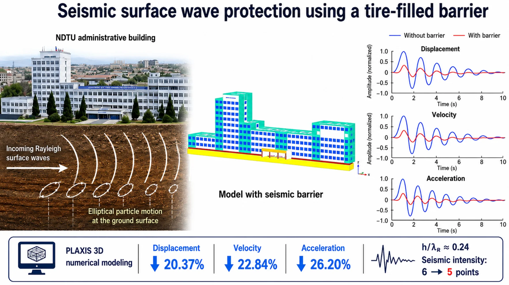
Seismic surface waves affecting the administrative building of Namangan State Technical University were numerically modeled using PLAXIS 3D. Displacement, velocity, and acceleration amplitudes at selected points were evaluated, and the reduction of structural vibrations with a seismic barrier was analyzed. A 1 m thick and 3 m deep tire-particle seismic barrier was placed along the foundation perimeter. The results showed a significant decrease in surface-wave amplitudes, confirming the effectiveness of the proposed protection method. The findings demonstrate that seismic barriers can effectively improve the seismic safety of buildings in active seismic regions.
Highlights
- Rayleigh-wave-induced vertical displacement, velocity, and acceleration of the NDTU administrative building were numerically simulated using PLAXIS 3D.
- A 1 m thick and 3 m deep tire-filled barrier installed around the foundation perimeter reduced displacement by 20.37%, velocity by 22.84%, and acceleration by 26.20%
- The relative barrier depth h/λR ≈ 0.24 confirms the effective attenuation of Rayleigh waves and supports the reduction of seismic intensity from 6 to 5 points.
- Tire-derived particles can be effectively used as a seismic surface-wave barrier for improving the dynamic safety of buildings.
- The proposed barrier provides a practical and sustainable solution for vibration and seismic protection of structures.
1. Introduction
The implementation of the tasks defined in the Decree of the President of the Republic of Uzbekistan No. PF-144 dated May 30, 2022, “On measures to further improve the system for ensuring seismic safety in the Republic of Uzbekistan,” namely the development of effective solutions aimed at preventing deficiencies or problems in construction activities, is considered scientifically and practically relevant [1]. During an earthquake, seismic surface waves propagating in the soil medium are among the wave types that cause the greatest damage to buildings and structures. Of the total seismic energy, approximately 7 % is carried by longitudinal P-waves, 26 % by transverse S-waves, and about 67 % by seismic surface waves. Nearly two-thirds of the seismic wave energy corresponds to Rayleigh waves, which attenuate more slowly with distance and depth in the soil compared to body waves. These waves propagate with high energy in the near-surface soil layers and induce significant vibrations in structural elements [2].
Fig. 1Deformations produced by surface waves: a) Rayleigh wave; and b) Love wave
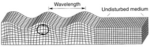
a)
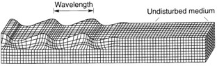
b)
The present study investigates the propagation of seismic surface waves affecting the administrative building of Namangan State Technical University and evaluates the effectiveness of methods for reducing their impact through numerical modeling. The research was carried out using the PLAXIS 3D software package based on the finite element method. The effectiveness of the proposed engineering solution was assessed by performing a comparative analysis of vibration parameters of the building under conditions without a seismic barrier and with a seismic barrier.
2. Methods
For solving this problem, the selected model has a length of 200 m, a width of 100 m, and a depth of 50 m. The soil profile consists of a sandy loam layer with a thickness of 1 m and a gravelly soil layer with a thickness of 49 m. The building is 123 m long, 27 m wide, and 34.05 m high, and its basement is located at a depth of 3 m below ground level.
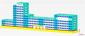
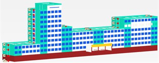
Fig. 2Exterior view of the building

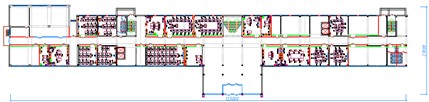
Fig. 3First-floor wall layout of the building
We consider the problem as one of wave propagation in an inhomogeneous half-space within the framework of the theory of elasticity. After placing the building on the boundary of the half-space, the problem becomes an inhomogeneous one with complex geometry, which cannot be solved by analytical methods. Therefore, the problem is solved using numerical methods, in particular the finite element method. It is known that numerical methods cannot be directly applied to an infinite domain. For this reason, the infinite half-space is replaced by a finite domain in the form of a parallelepiped. In this case, boundary conditions that ensure the propagation of waves toward infinity at the model boundaries are imposed as follows [3]:
where and denote the normal and shear stresses, respectively; , , and represent the velocity components of the boundary nodes in the , , and directions; and are the compressional (P-wave) and shear (S-wave) velocities, respectively; and are dimensionless coefficients related to absorbing boundary conditions, typically taken as 1 and 1; is the material density.
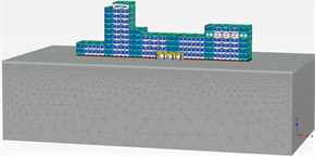
Viscous (absorbing) boundary conditions were applied in the -direction and at the bottom boundary in the -direction to simulate wave propagation in a semi-infinite medium and to prevent artificial reflections. No special boundary condition was assigned in the -direction. The study domain was discretized into 37 916 finite elements and 77 473 nodes. The finite elements were selected in the form of irregular tetrahedra. The order of the system of differential equations of motion was 77 473×3 = 232 419 (Fig. 5).
Fig. 4Application of boundary conditions
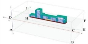
Fig. 5Discretization of the model into finite elements
The system of differential equations describing the motion of the mechanical system under the action of dynamic loading is expressed as follows:
where is the mass matrix, is the damping matrix, is the stiffness matrix, and is the dynamic load vector. displacement, velocity, and acceleration are continuous functions of time.
A computational model of the research object was developed using the PLAXIS 3D software package. Within the scope of the study, the soil at the site of Namangan State Technical University was represented by sandy loam and gravelly layers.
To solve the problem, the administrative building of Namangan State Technical University (Fig. 6) and a seismic protection barrier placed along the outer perimeter of the administrative building foundation were modeled (Fig. 7).
Fig. 6Model without a seismic barrier
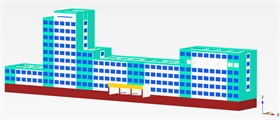
Fig. 7Model with a seismic barrier
Rayleigh surface waves propagate along the free surface of a semi-infinite elastic medium and are characterized by elliptical particle motion in the vertical plane (-). Unlike body waves (P and S waves), Rayleigh waves are confined to the near-surface region and exhibit an exponential decay of amplitude with depth. This behavior is consistent with classical wave propagation theory in elastic half-space models. The propagation of seismic surface waves was simulated by introducing a harmonic dynamic excitation into the numerical model. A harmonic excitation was adopted as a simplified representation to isolate the dominant frequency effect of Rayleigh surface waves. Although real seismic excitations are non-stationary and broadband, harmonic loading is widely used in numerical studies to investigate wave-barrier interaction mechanisms under controlled conditions. The excitation was applied as a prescribed displacement at the base boundary of the computational domain, allowing for a clear evaluation of wave propagation and attenuation mechanisms. The excitation function is defined as:
where is the amplitude and 10 Hz represents the dominant frequency range of seismic surface waves affecting low- to mid-rise structures. To prevent artificial reflection of waves at the model boundaries, viscous absorbing boundary conditions were applied on the lateral and bottom boundaries. These boundaries were defined based on the shear and compressional wave velocities of the soil layers. Furthermore, Rayleigh damping was incorporated into the model, where the damping matrix is expressed as:
where and are damping coefficients determined according to the target damping ratio of the soil medium. The dynamic analysis was performed using a time-stepping scheme, ensuring numerical stability and accurate simulation of wave propagation.
To identify and compare the seismic surface waves affecting the building, a total of 44 observation points were selected on the structure (Fig. 8).
Fig. 8Observation points on the building
3. Results and discussion
The values of vertical displacement , velocity , and acceleration at the selected observation points were comparatively analyzed to evaluate the influence of seismic surface waves on the building. For example, the coordinates of point 32 are 138 m, 96 m, and 7.3.
Fig. 9Comparison graph of displacement at observation point 32, m: without seismic barrier (Blue line), with seismic barrier (Red line)
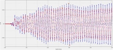
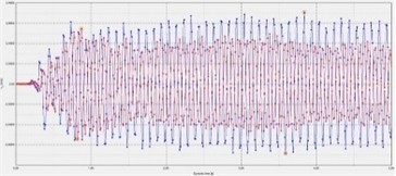
Fig. 10Comparison graph of velocity at observation point 32, m/s: without seismic barrier (Blue line), with seismic barrier (Red line)
As shown in Fig. 9, at observation point 32 of the building model without any surrounding barrier, the maximum vertical displacement along the z-axis was 0.00153 m. When a trench barrier filled with tire particles was introduced, the maximum displacement decreased to 0.00122 m. A comparative analysis showed that, relative to the case without a surrounding barrier, the tire-particle barrier provides a seismic mitigation efficiency of 20.37 %.
As shown in Fig. 10, at observation point 32 of the building model without any surrounding barrier, the maximum vertical velocity along the -axis was 0.070 m/s. When a trench barrier filled with tire particles was introduced, the maximum velocity decreased to 0.054 m/s. A comparative analysis showed that, relative to the case without a surrounding barrier, the tire-particle barrier provides a seismic mitigation efficiency of 22.84 %.
Fig. 11Comparison graph of acceleration at observation point 32, m/s2: without seismic barrier (Blue line), with seismic barrier (Red line)
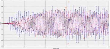
As shown in Fig. 11, at observation point 32 of the building model without any surrounding barrier, the maximum vertical acceleration along the -axis was 759 m/s2. When a trench barrier filled with tire particles was introduced, the maximum acceleration decreased to 0.560 m/s2. A comparative analysis showed that, relative to the case without a surrounding barrier, the tire-particle barrier provides a seismic mitigation efficiency of 26.20 %.
The study was conducted in a two-layer soil medium. The near-surface layer consisted of sandy loam with a thickness of 1 m, for which the Poisson’s ratio was taken as = 0.35. The shear wave velocity = 104.9 m/s was determined based on site-specific soil properties and represents the average value for the sandy loam layer. This value is rounded to one decimal place for consistency. Beneath this layer, gravelly soil was assumed, with a Poisson’s ratio of = 0.30 and a shear wave velocity of = 133.7 m/s. Under dynamic loading, it is necessary to determine the main parameters of Rayleigh-type surface waves propagating in the soil medium, as these parameters are important for evaluating the effectiveness of the seismic barrier. In a two-layer soil medium, the main energy of Rayleigh surface waves propagates in the near-surface layers while also penetrating to a certain depth. Since the model depth is 50 m, the values of shear wave velocity and Poisson’s ratio are determined as effective values based on the influence depth. The effective shear wave velocity is determined using the harmonic mean as follows:
where: is the model depth, is the thickness of the first layer, is the thickness of the second layer.
The effective Poisson’s ratio is determined using the weighted average as follows:
The velocity of Rayleigh surface waves depends on the physical and mechanical properties of the soil and is determined by the following expression [5]:
The wavelength of the Rayleigh surface wave is determined as a function of frequency as follows [5]:
The effectiveness of the seismic barrier depends on the relative depth and can be expressed as follows:
Researcher Richard D. Woods determined that the reduction in vibration amplitude begins when the relative depth of the seismic barrier is within the range 0.2-0.3, and that higher attenuation efficiency can be achieved when the depth is increased to the range 0.6-1.0 [5]. The obtained results show that selecting the relative depth of the seismic barrier as 0.24 is scientifically justified and confirms its effectiveness. The reduction in vibration amplitude at the nodes of the preselected observation points on the building can be explained by this condition, since the main energy of Rayleigh waves propagates in the near-surface layer of the soil [6]-[7].
According to the research conducted by B. Rakhmonov and M. Siddiqov, for earthquake intensities in the range of 6-10 points, the vibration parameters of buildings corresponding to the applied seismic load are determined according to Table 1 [8].
According to Table 1, the displacement in the building was determined under a seismic intensity of 6 points. When the seismic barrier was applied, the influence of surface waves decreased from 6 points to 5 points. This result indicates that the structural and geometric parameters of the selected seismic barrier were appropriately chosen and confirms its practical effectiveness.
Table 1Vibration parameters [8]
Earthquake intensity, points | Building point displacement interval, m | Building point velocity amplitude interval, m/s | Building point acceleration amplitude interval, m/s2 |
6 | 0.0015-0.003 | 0.03.0-0.06 | 0.30-0.60 |
7 | 0.0031-0.060 | 0.061-0.120 | 0.61-1.20 |
8 | 0.0061-0.0120 | 0.121-0.240 | 1.21-2.40 |
9 | 0.0121-0.0240 | 0.241-0.480 | 2.41-4.80 |
10 | 0.0241-0.0480 | 0.481-0.900 | 4.81-9.60 |
4. Conclusions
The present study determined the key parameters of Rayleigh surface waves and evaluated the effective physical and mechanical properties of a layered soil medium. The effective shear wave velocity was found to be 132.97 m/s, and the effective Poisson’s ratio was 0.301. Based on these values, the Rayleigh wave velocity was calculated as 123.17 m/s, with a corresponding wavelength of 123.17/10 ≈ 12.31 m for an excitation frequency of 10 Hz. A seismic barrier consisting of a 3 m deep trench filled with tire-derived particles was implemented along the building foundation. Numerical results from PLAXIS 3D simulations showed a significant reduction in displacement, velocity, and acceleration amplitudes, with an overall efficiency of approximately 20-30 %. The relative barrier depth ≈ 0.24 falls within the effective range reported in previous studies, confirming the validity of the selected design. The results demonstrate that the proposed seismic barrier provides an effective, practical, and sustainable solution for reducing the impact of seismic surface waves on buildings.
References
-
D. Fazilova, K. Magdiev, M. Makhmudov, and A. Fazilov, “A multi-criteria GIS model for geohazard assessment in the Charvak reservoir area, Uzbekistan,” The Egyptian Journal of Remote Sensing and Space Sciences, Vol. 28, No. 3, pp. 587–596, Sep. 2025, https://doi.org/10.1016/j.ejrs.2025.09.003
-
S. L. Kramer, “Performance-based design methodologies for geotechnical earthquake engineering,” Bulletin of Earthquake Engineering, Vol. 12, No. 3, pp. 1049–1070, 2013, https://doi.org/10.1007/s10518-013-9484-x
-
S. Yuldashev, A. Abdunazarov, S. Jumaboyeva, M. Boytemirov, and Y. Tillaboyev, “Attenuation of seismic surface waves affecting the building using various barriers,” in AIP Conference Proceedings, Vol. 3282, No. 1, p. 030016, Apr. 2025, https://doi.org/10.1063/5.0265304
-
Y. Achaoui, T. Antonakakis, S. Brûlé, R. V. Craster, S. Enoch, and S. Guenneau, “Clamped seismic metamaterials: ultra-low frequency stop bands,” New Journal of Physics, Vol. 19, No. 6, p. 063022, Jun. 2017, https://doi.org/10.1088/1367-2630/aa6e21
-
R. D. Woods, “Screening of surface wave in soils,” Journal of the Soil Mechanics and Foundations Division, Vol. 94, No. 4, pp. 951–979, Apr. 1968, https://doi.org/10.1061/jsfeaq.0001180
-
A. Alzawi and M. Hesham El Naggar, “Full scale experimental study on vibration scattering using open and in-filled (GeoFoam) wave barriers,” Soil Dynamics and Earthquake Engineering, Vol. 31, No. 3, pp. 306–317, Mar. 2011, https://doi.org/10.1016/j.soildyn.2010.08.010
-
A. Moussa and H. El Naggar, “Numerical evaluation of buried wave barriers performance,” International Journal of Geosynthetics and Ground Engineering, Vol. 6, No. 4, p. 56, Nov. 2020, https://doi.org/10.1007/s40891-020-00240-z
-
B. Rakhmonov, I. Safarov, M. Teshaev, and R. Nafasov, “Vibrations of a deformed half-space with inclusion under the influence of surface waves,” E3S Web of Conferences, Vol. 274, p. 03027, Jun. 2021, https://doi.org/10.1051/e3sconf/202127403027
About this article

The authors have not disclosed any funding.
The datasets generated during and/or analyzed during the current study are available from the corresponding author on reasonable request.
The authors declare that they have no conflict of interest.
