Abstract
This paper addresses the inverse synthesis of a disk-cam mechanism used as a cam-type vibration exciter with an elastically coupled oscillating mass. The primary aim is to determine the cam geometry directly from a prescribed acceleration program of the working body. The mechanism is modelled as an in-line translating flat-faced follower driven by a rotating cam and coupled to the oscillating mass through a spring, while a return spring provides force closure. The cam profile is obtained as the envelope of follower-face lines, yielding closed-form parametric equations for the working profile as well as analytical expressions for pressure angle and curvature radius. An acceleration-driven synthesis chain is formulated, where the required follower motion is computed from an inverse elastic model (algebraic for undamped coupling). Design inequalities for the base-circle radius are proposed to satisfy pressure-angle limits and prevent undercutting. A near vibro-impact case study is simulated in Wolfram Mathematica. In contrast to direct kinematic studies of predefined excitation mechanisms, the present work solves an inverse design problem in which the disk-cam profile is synthesized from a prescribed acceleration law of an elastically coupled oscillating mass. The practical outcome is an explicit analytical link between the target output acceleration, follower motion, admissible base-circle radius, pressure angle, and curvature constraints.
Highlights
- An inverse synthesis methodology for cam-type vibration exciters with elastically coupled masses is developed. It uses an envelope approach to derive closed-form parametric equations for the profile and its analytical geometric qualities.
- Design inequalities for the base-circle radius are established based on pressure-angle and curvature limits. Curvature constraints are the dominant factor for aggressive, "impact-like" acceleration programs.
- A near vibro-impact case study at 1200 rpm achieves short 76g acceleration pulses with a 100 mm base-circle cam. Wolfram Mathematica simulations validate the asymmetric kinematics of the oscillating body.
1. Introduction
Vibration-driven machines and mechanisms enable high-throughput processing and compact actuation, but their performance often relies on operation near resonance, where small parameter variations can cause large response changes, overloads, or intermittent contact. Consequently, recent research increasingly treats the exciter not as a fixed periodic source, but as a synthesizable subsystem whose motion law can be matched to the host structure’s dynamics and constraints.
The study [1] applies invariant-based inverse design to prescribe slider motion so that spring-force projections compensate inertia, motivating acceleration-driven cam synthesis for balancing and load reduction. The paper [2] proposes a controllable crank–slider with cam-actuated variable geometry, highlighting implementable links between geometry, springs, and targeted motion. Vibro-impact and contact sensitivity are emphasized by [3], where a small clearance (“gap”) strongly affects locomotion speed; similarly, realistic interaction models in compaction and conveying systems [4], [5] show that contact continua and tuning around resonance reshape kinematics and loads, requiring experimental verification. Multi-mass modeling and validation further demonstrate that credible inverse synthesis depends on parameter identification and resonance characterization [6], while structural feasibility constraints – especially spring durability under vibro-impact loading – can limit aggressive acceleration programs even when dynamically favorable [7], [8].
A key controversy concerns how follower detachment (jump) should be predicted and mitigated: via preload and classical separation criteria, or through contact-aware simulation augmented by data-driven predictors. Nonsmooth dynamics with unilateral constraints provides a rigorous physics baseline for impact-rich cam-follower systems [9], and frictional rolling/sliding studies show that regime changes can alter response under the same motion law [10]. In parallel, learning-based and hybrid models (e.g., RNN predictors and physics-informed neural architectures) support fast screening and improved extrapolation across operating conditions [11], [12]. Contact compliance and motion-law choice jointly govern periodic detachment patterns [13], and inverse cam design is naturally formulated as a constrained multi-objective problem with motion parametrizations (e.g., Bézier curves, high-order polynomials, jerk minimization) enabling constraint handling but exhibiting diminishing returns at very high orders [14-17].
Overall, the literature points to an integrated inverse workflow that combines motion-law shaping, multi-mass dynamics, contact modeling, and constrained optimization, using data-driven models primarily as accelerators rather than replacements for physics. However, comparatively few studies formulate the inverse problem in which the required acceleration of the working body is prescribed first, and the geometry of a cam-type exciter is then synthesized with explicit checks of pressure-angle and curvature admissibility for an elastically coupled output stage. The present paper addresses this analytical gap by substantiating an acceleration-driven cam profile synthesis methodology for a cam-type vibration exciter with an elastically coupled oscillating mass.
At this point, the specific novelty relative to the authors’ previous studies should be stated explicitly. Earlier works of the group addressed cam-actuated variable-geometry mechanisms and controllable crank-slider systems, as well as vibration exciters based on crank and planetary mechanisms, where the main emphasis was placed on direct kinematic analysis, trajectory generation, or parameter justification of mechanisms with prescribed geometry [1]-[6]. The present paper addresses a different inverse problem. Here, the working mass is elastically coupled to the follower and is therefore not kinematically identical to the follower motion; consequently, the synthesis starts from a prescribed acceleration law of the working body, reconstructs the follower motion through the elastic coupling, and only then determines the cam geometry. The novelty of the paper thus lies not simply in using a cam for vibration generation, but in formulating and demonstrating an acceleration-driven inverse synthesis chain for a cam-type vibration exciter, together with explicit geometric feasibility conditions for pressure angle and curvature in a near vibro-impact regime.
Specifically, the paper contributes: an inverse mapping from the prescribed motion law of the oscillating mass to the follower motion for the undamped elastic coupling; closed-form envelope-based equations of the cam profile for an in-line flat-faced follower; analytical lower-bound inequalities for base-circle radius imposed by pressure-angle and no-undercutting criteria; and a worked near vibro-impact example showing that curvature, rather than pressure angle, may become the governing constraint on cam size.
2. Research methodology
2.1. Mechanism description
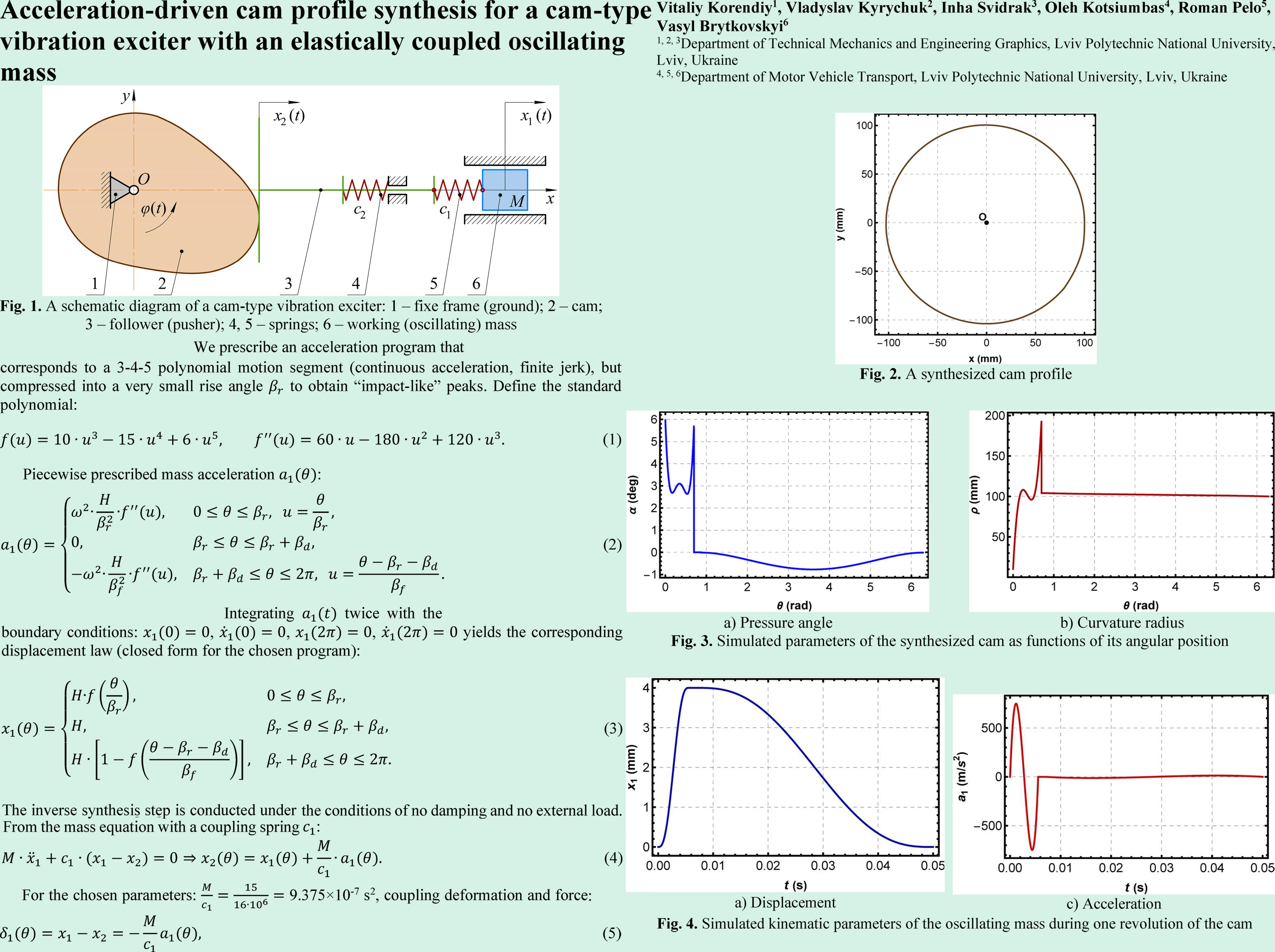
Fig. 1 shows a disk cam (link 2) rotating about a fixed axis at with angle . The cam acts on a translating pusher (follower) (link 3) that moves along the horizontal axis and whose displacement is denoted . A spring (element 4) connects the follower to the frame and provides force closure, ensuring continuous contact between cam and follower. The working (oscillating) mass (element 6) slides along the same axis with displacement and is coupled to the follower through spring (element 5).
Key geometric and kinematic features of the mechanism are the following: 1) translating follower motion is collinear with the cam centerline (in-line translating follower, offset ); 2) the follower contact end is modeled as a flat face, i.e., a flat-faced translating follower is considered; 3) the working mass is not rigidly constrained by the cam; it is excited via the elastic coupling , which is central for the inverse synthesis from a prescribed mass acceleration law.
Fig. 1A schematic diagram of a cam-type vibration exciter: 1 – fixe frame (ground); 2 – cam; 3 – follower (pusher); 4, 5 – springs; 6 – working (oscillating) mass
2.2. Worked example: cam synthesis for a near vibro-impact operating mode
This example follows the mechanism of Fig. 1: a disk cam (2) drives an in-line translating flat-faced follower (pusher) (3) with displacement , while the working mass (6) is excited through the coupling spring (5) and moves as ; contact is maintained by a return spring (4). To keep the example analytically transparent (typical for synthesis stage), we assume: 1) constant cam speed const (one revolution per excitation period); 2) negligible damping in the coupling (so the inverse relation is algebraic); 3) no external technological force on the mass (); 4) follower inertia neglected in kinematic synthesis (contact maintenance to be checked later via and preload). These assumptions intentionally define a synthesis-stage model used to expose the analytical structure of the inverse problem; their implications for applicability to practical cam-follower systems are discussed explicitly in Section 4.
Let us intentionally create a very short “impact-like” forward stroke (high acceleration and jerk) and a long slow return (low acceleration). This is a classic way to approach vibro-impact behavior while keeping the motion kinematically admissible (no true discontinuities). The following input parameters are introduced: 1) cam speed: 1200 rpm 20 Hz, 125.664 rad/s, period 0.05 s; 2) mass 15 kg; 3) coupling stiffness: 16×106 N/m (stiff elastic link); 4) contact spring 0.30×10⁶ N/m with preload (used later for contact check); 5) target stroke of the oscillating mass 4 mm = 0.004 m; 6) cam angle segmentation per revolution: fast forward stroke (“impact-like”) 40° = 0.6981 rad; top dwell: 10° = 0.1745 rad; slow return: 310° = 5.4105 rad. Corresponding time intervals for forward stroke, dwell, and return: 5.56 ms, 1.39 ms, 43.06 ms Let be the cam angle. We prescribe an acceleration program that corresponds to a 3-4-5 polynomial motion segment (continuous acceleration, finite jerk), but compressed into a very small rise angle to obtain “impact-like” peaks. Define the standard polynomial:
Piecewise prescribed mass acceleration :
This acceleration law is periodic and satisfies 0 at segment boundaries (because 0). Resulting acceleration levels: 1) peak during fast forward stroke: ≈ +748.25 m/s2 ≈ 76.3 g, –748.25 m/s2 ≈ –76.3 g; 2) peak during slow return: 12.46 m/s2 ≈ 1.27 g. This strong asymmetry (very high short pulse and long gentle return) is what makes the regime “close to vibro-impact”. Integrating twice with the boundary conditions: , , , yields the corresponding displacement law (closed form for the chosen program):
Near-impact kinematic indicator: the peak forward velocity of the mass is 1.35 m/s, whereas the backward return velocity magnitude is much smaller (approximately 0.17 m/s), confirming “fast-hit and slow-recovery” behavior. The inverse synthesis step is conducted under the conditions of no damping and no external load. From the mass equation with a coupling spring :
For the chosen parameters: 9.375×10⁻⁷ s2, coupling deformation and force is as follows:
so the peak coupling deformation is 0.701 mm, and the peak spring force is 11.2 kN, (equivalently ). For the cam synthesis (with flat-faced translating follower), let us set the cam lift equal to the follower displacement up to a constant shift:
In this example, 0, hence . The computed lift amplitude 4.00 mm. Now, let us check the two key geometric constraints for a flat-faced follower:
– Pressure angle constraint and the design inequality:
– Undercutting and curvature constraint:
Computed minimum base circle radius (dominant is curvature): 89.74 mm. Let us adopt a practical margin 100 mm. Resulting geometric qualities are as follows: 1) maximum pressure angle: 30°; 2) minimum curvature radius: 10.26 mm > 0; 3) maximum cam blank radius (accounting for : 104.52 mm. So a practical blank diameter is about 210 mm (plus machining allowance).
With the synthesized lift and selected , the cam profile in cam-fixed coordinates is:
3. Results and discussion
The synthesis procedure of Section 2.2 was implemented in Wolfram Mathematica to generate the disk-cam profile for an in-line translating flat-faced follower (envelope solution), and to validate the time-domain kinematics and dynamics of the oscillating body (mass ) excited through the elastic coupling according to the mechanism in Fig. 1.
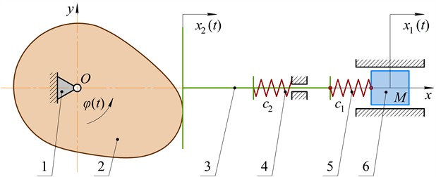
The cam working profile was plotted as the parametric curve described by Eq. (11), where is the synthesized lift of the translating follower and is the base-circle radius. The resulting profile is shown in Fig. 2. The following two observations are important:
1. A near-circular shape is expected. In the adopted “near vibro-impact” regime, the stroke is small compared to the base circle (here 4 mm, 100 mm), therefore, the profile differs from a circle only slightly on the global scale. This is why Fig. 2 visually resembles a circle.
2. The curve is closed, and the cam axis is correctly located at . Fig. 2 explicitly marks the rotation center at the origin of the cam-fixed coordinate system.
Fig. 2A synthesized cam profile
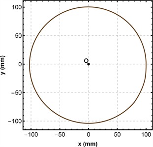
For an in-line translating follower (offset 0), the pressure angle is computed by Eq. (7). The obtained dependence is presented in Fig. 3(a). The curve has a characteristic structure: 1) during the fast rise interval (), exhibits two local maxima and reaches about 6°, which is very small for cam mechanisms (typical admissible limits are much higher, depending on design practice and lubrication); 2) during the dwell, 0 because 0 (the follower position is constant); 3) during the slow return, becomes slightly negative with a minimum of roughly –0.8°, then returns to zero near . From an engineering viewpoint, Fig. 3(a) indicates low side thrust on the follower guide and therefore favorable friction and wear conditions – despite the strongly asymmetric (near vibro-impact) timing.
For a flat-faced translating follower, the curvature radius of the cam profile (in the adopted envelope formulation) can be evaluated by Eq. (9). A physically manufacturable profile without cusps/undercutting requires The computed dependence is shown in Fig. 3(b). The horizontal plateau at approximately 100 mm corresponds to the intervals where is constant and 0 (dwell and “almost quasi-static” parts), so the profile locally behaves like a circular arc dominated by . The large excursions of within the fast rise segment reflect the fact that a near vibro-impact regime produces high derivatives of the lift law (in particular, large negative values of ), hence high curvature demand.
Fig. 3Simulated parameters of the synthesized cam as functions of its angular position
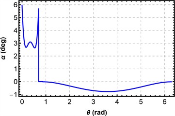
a) Pressure angle
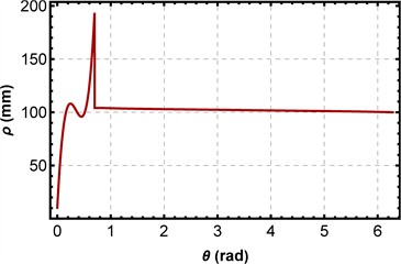
b) Curvature radius
A notable outcome of Fig. 3 is that the limiting geometric factor is not the pressure angle but the curvature radius. In the present example, the pressure-angle requirement remains mild, whereas the minimum feasible base-circle radius is determined by the no-undercutting condition. This result is important for the design of aggressive cam-type vibration exciters because it shows that strongly asymmetric, near vibro-impact excitation laws can remain acceptable from the follower-guidance viewpoint while still imposing severe local geometric demands on the cam profile. Therefore, the proposed framework does not merely reproduce a cam contour; it reveals which geometric criterion becomes dominant when the output-stage acceleration law is prescribed a priori.
4. Limitations of the proposed approach
The proposed methodology should be interpreted as a synthesis-stage analytical framework, and several limitations should be acknowledged. First, the inverse mapping between the oscillating mass and follower motion was derived for the undamped and unloaded case, which leads to the algebraic relation between the follower displacement and the prescribed output acceleration. When viscous damping in the coupling or a nonzero technological load act on the working body, the inverse problem is no longer algebraic and requires a dynamic reconstruction involving displacement, velocity, and force histories.
Second, the worked example assumes constant cam angular speed. Therefore, the present model does not include drive dynamics, torque fluctuations, limited-power-source effects, or possible speed variation near resonance, although such effects may be relevant for practical vibration machines.
Third, follower inertia, friction in the guide-contact pair, and explicit contact-separation criteria were not included in the synthesis model. Consequently, although the return spring is introduced in the mechanism scheme, the positivity of the normal reaction, possible follower jump, and impact severity at the cam-follower interface were not verified in the present study.
Fourth, the formulation was developed specifically for an in-line flat-faced translating follower. Extension to roller followers, offset followers, oscillating followers, or spatial cam geometries would require modified envelope, pressure-angle, and curvature relations.
Fifth, the present paper evaluates geometric admissibility mainly through pressure-angle and curvature criteria. Although the coupling force level is estimated, detailed contact-stress, Hertzian pressure, fatigue, lubrication, and manufacturing-tolerance analyses are beyond the current scope.
Finally, the methodology is illustrated by a single near vibro-impact numerical example and has not yet been experimentally validated. Therefore, the obtained numerical values should be interpreted as rational preliminary-design estimates rather than final operating limits. These limitations do not diminish the usefulness of the proposed framework at the preliminary synthesis stage, but they define the current scope of its applicability.
5. Conclusions
This paper developed an acceleration-driven inverse synthesis framework for a cam-type vibration exciter with an elastically coupled oscillating mass. Unlike direct analyses of mechanisms with predefined geometry, the proposed approach starts from a prescribed acceleration law of the working body, reconstructs the follower motion through the elastic coupling, and then synthesizes the disk-cam profile while checking pressure-angle and curvature admissibility. For the in-line flat-faced follower, the envelope approach yields closed-form parametric equations and compact analytical expressions for the pressure angle and curvature radius (design inequalities) that allow direct geometric validation of the synthesized profile and are convenient for preliminary engineering selection of the base-circle radius.
The inverse mapping from the prescribed motion of the oscillating body to the follower motion was formalized for the undamped coupling case (algebraic relation). Two design inequalities for selecting the base-circle radius were emphasized: a pressure-angle bound and a curvature (no-undercutting) bound. The methodology highlights that for aggressive acceleration programs – especially near vibro-impact regimes – the curvature condition often becomes the dominant limitation on cam geometry.
In the near vibro-impact numerical example (1200 rpm, 4 mm, 40°, 10°, 310°), the prescribed program produced a short acceleration pulse of about ±750 m/s2 (approximately ±76 g). The computed minimum feasible base-circle radius was 89.74 mm; selecting 100 mm yielded 5.96°, 10.26 mm, and a practical blank diameter of about 210 mm.
The reported results should be interpreted within the limitations of a synthesis-stage model: undamped coupling, constant cam speed, no external technological load, neglected follower inertia, and absence of explicit contact-separation, friction, stress, and experimental verification. Within this scope, the study still shows that under aggressive near vibro-impact excitation laws the curvature constraint can govern the feasible cam size even when pressure angles remain small. Further development of the approach should include explicit contact-maintenance verification (normal reaction positivity) with realistic return-spring preload, follower inertia, and friction, as well as multi-objective optimization of , rise and return angles, and smoothing order to reduce peak curvature demand while preserving the required acceleration program.
References
-
V. Korendiy, V. Pasika, V. Kyrychuk, R. Kachmar, V. Borovets, and V. Brytkovskyi, “Analysis and synthesis of a cam-actuated variable-length crank for frame saw drives with perpendicular springs,” Vibroengineering Procedia, Vol. 60, pp. 8–15, Dec. 2025, https://doi.org/10.21595/vp.2025.25497
-
V. Korendiy, V. Pasika, V. Kyrychuk, B. Vasyliv, P. Hashchuk, and I. Zakhara, “Analysis and synthesis of a controllable crank-slider mechanism with parallel springs for frame saws,” Vibroengineering Procedia, Vol. 59, pp. 41–49, Sep. 2025, https://doi.org/10.21595/vp.2025.25178
-
V. Korendiy, O. Kachur, V. Gurskyi, and P. Krot, “Studying the influence of the impact gap value on the average translational speed of the wheeled vibration-driven robot,” Engineering Proceedings, Vol. 24, No. 1, p. 25, Sep. 2022, https://doi.org/10.3390/iecma2022-12897
-
V. Korendiy and O. Kachur, “Dynamic behavior of a vibratory plate compactor working on a horizontal elastic-viscous-plastic surface,” in Lecture Notes in Mechanical Engineering, pp. 434–443, Sep. 2022, https://doi.org/10.1007/978-3-031-16651-8_41
-
O. Kachur and V. Korendiy, “Dynamic behavior of vibratory screening conveyor equipped with crank-type exciter,” in Lecture Notes in Mechanical Engineering, pp. 44–53, May 2023, https://doi.org/10.1007/978-3-031-32774-2_5
-
V. Korendiy, O. Lanets, O. Kachur, P. Dmyterko, and R. Kachmar, “Determination of inertia-stiffness parameters and motion modelling of three-mass vibratory system with crank excitation mechanism,” Vibroengineering Procedia, Vol. 36, pp. 7–12, Mar. 2021, https://doi.org/10.21595/vp.2021.21924
-
V. Gursky and I. Kuzio, “Dynamic analysis of a rod vibro-impact system with intermediate supports,” Acta Mechanica et Automatica, Vol. 12, No. 2, pp. 127–134, Jun. 2018, https://doi.org/10.2478/ama-2018-0020
-
G. Filimonikhin, V. Yatsun, A. Matsui, V. Kondratets, and V. Pirogov, “Selection and research of stability of the steady state motions of a single-mass resonance vibromating machine working on the Somerfeld effect,” Eastern-European Journal of Enterprise Technologies, Vol. 3, No. 7(117), pp. 68–76, Jun. 2022, https://doi.org/10.15587/1729-4061.2022.259567
-
P. Flores, R. Leine, and C. Glocker, “Application of the nonsmooth dynamics approach to model and analysis of the contact-impact events in cam-follower systems,” Nonlinear Dynamics, Vol. 69, No. 4, pp. 2117–2133, Apr. 2012, https://doi.org/10.1007/s11071-012-0413-3
-
S. Sundar, J. T. Dreyer, and R. Singh, “Rotational sliding contact dynamics in a non-linear cam-follower system as excited by a periodic motion,” Journal of Sound and Vibration, Vol. 332, No. 18, pp. 4280–4295, Sep. 2013, https://doi.org/10.1016/j.jsv.2013.02.035
-
W. de Groote, S. van Hoecke, and G. Crevecoeur, “Prediction of follower jumps in cam-follower mechanisms: The benefit of using physics-inspired features in recurrent neural networks,” Mechanical Systems and Signal Processing, Vol. 166, p. 108453, Mar. 2022, https://doi.org/10.1016/j.ymssp.2021.108453
-
W. de Groote, S. van Hoecke, and G. Crevecoeur, “Physics-based neural network models for prediction of cam-follower dynamics beyond nominal operations,” IEEE/ASME Transactions on Mechatronics, Vol. 27, No. 4, pp. 2345–2355, Aug. 2022, https://doi.org/10.1109/tmech.2021.3101420
-
X. Zhang, G. Luo, Z. Wang, X. An, and F. Yin, “Dynamics analysis of a cam with flat-bottomed follower system,” Scientific Reports, Vol. 15, No. 1, Aug. 2025, https://doi.org/10.1038/s41598-025-14991-0
-
F. Hamza, H. Abderazek, S. Lakhdar, D. Ferhat, and A. R. Yıldız, “Optimum design of cam-roller follower mechanism using a new evolutionary algorithm,” The International Journal of Advanced Manufacturing Technology, Vol. 99, No. 5-8, pp. 1267–1282, Aug. 2018, https://doi.org/10.1007/s00170-018-2543-3
-
S. Cardona, E. E. Zayas, L. Jordi, and P. Català, “Synthesis of displacement functions by Bézier curves in constant-breadth cams with parallel flat-faced double translating and oscillating followers,” Mechanism and Machine Theory, Vol. 62, No. 1, pp. 51–62, Apr. 2013, https://doi.org/10.1016/j.mechmachtheory.2012.11.004
-
M. Todorović, G. Marković, R. Bulatović, M. Bošković, and M. Savković, “Cam displacement curve optimization for minimal jerk using search and rescue optimization algorithm,” Proceedings of the Institution of Mechanical Engineers, Part C: Journal of Mechanical Engineering Science, Vol. 238, No. 21, pp. 10332–10343, Jul. 2024, https://doi.org/10.1177/09544062241260566
-
K. Özgür and F. Pasin, “Separation phenomena in force closed cam mechanisms,” Mechanism and Machine Theory, Vol. 31, No. 4, pp. 487–499, May 1996, https://doi.org/10.1016/0094-114x(95)00086-e
About this article

The authors have not disclosed any funding.
The datasets generated during and/or analyzed during the current study are available from the corresponding author on reasonable request.
The authors declare that they have no conflict of interest.
