Abstract
This paper presents a kinematic synthesis of a groove-type disk cam that directly drives sliders in a novel internal-combustion engine architecture. The synthesis is formulated in an invariant (normalized) space and enforces zero acceleration at phase boundaries while embedding a quasi-constant-velocity segment in the mid-portion of the compression (retraction) phase. An arbitrary shaping function is introduced to generate a family of admissible motion laws; a constrained optimization (series truncated to four terms) minimizes the peak acceleration under a prescribed bound on velocity, yielding a PLM with a quasi-constant-velocity interval of approximately 39 % of the kinematic cycle (±5 %). The synthesized retraction law is paired with a sinusoidal approach (power) law to ensure zero endpoint accelerations for both phases. Cam profiles for the working and return strokes are constructed; maximum pressure angles remain within admissible limits across examined phase splits, including an experimental 65°/25° case. Compared with the sinusoidal baseline, the synthesized law retains a similar acceleration constant but reduces the velocity constant by approximately 31 %, indicating lower inertial loading and milder end-conditions that are favorable for mixture preparation and bearing lubrication. The results provide a compact, implementable route to motion programming for cam-driven reciprocators in internal-combustion engines and establish feasibility for multi-cylinder layouts.
Highlights
- A kinematic synthesis for a disk cam in a novel engine using invariant space and shaping functions is carried out. This ensures zero acceleration at phase boundaries and enables a quasi-constant-velocity segment to reduce inertial shocks.
- The optimized law achieves a quasi-constant-velocity interval for roughly 39% of the kinematic cycle. Compared to a sinusoidal baseline, it reduces the velocity constant by 31%, lowering inertial loading with similar peak acceleration.
- A novel engine architecture where sliders are directly driven by cam grooves, eliminating separate tappets and rollers, is validated. Pressure angle analysis confirms values remain within the admissible 30° limit for a 65°/25° phase split.
1. Introduction
Cam-follower mechanisms remain a cornerstone of motion programming in engines and machinery because they let designers impose displacement, velocity, acceleration and jerk (SVAJ) with high precision while respecting constraints such as pressure angle and contact stress [1], [2]. Classical motion programs (cycloidal, harmonic, and higher-order polynomials such as the 4-5-6-7 law) are still widely used because they offer continuous velocity/acceleration and bounded jerk, which helps limit vibration and wear [2]. Practical design rules also bound the pressure angle for translating followers (typically less than 30°) to avoid side-load-induced losses and jamming [2].
Beyond closed-form motion laws, modern cam synthesis often treats the profile as an optimization problem. Early work represented the cam law with B-splines to minimize objectives tied to dynamics and manufacturability [3]. Metaheuristic searches (e.g., particle swarm optimization) and fractional/piecewise polynomials have been used to reduce jerk and Hertzian stress while meeting boundary conditions [4], [5]. Introducing explicit control points into B- or classical splines provides additional degrees of freedom to damp SVAJ peaks and can be tuned with genetic or fuzzy approaches; Non-Uniform Rational B-Splines (NURBS) formulations generalize this strategy and have been validated in design studies and theses [6-8]. Recent studies continue to optimize high-order polynomials specifically for minimal jerk under practical constraints, showing measurable gains relative to conventional laws [9].
Parallel to kinematic synthesis, dynamic analyses of valve/translation trains emphasize flexible bodies, contact/friction, gyroscopic effects, and speed-dependent phenomena. Rigid-flexible models and experimental validations show that profile choice, shaft dynamics, and clearances strongly influence seating impacts, stress, and vibration; this has been demonstrated for conventional and desmodromic systems alike [10], [11]. Such results reinforce that cam laws designed to suppress boundary accelerations and to flatten mid-stroke velocity can materially improve dynamic performance while keeping pressure angles in allowable limits [2], [10], [11].
In this paper, we address a groove-type disk cam that directly drives sliders in a novel internal-combustion configuration. Our contribution is a kinematic synthesis that enforces zero acceleration at phase boundaries and a quasi-constant piston velocity interval mid-stroke, followed by checks on pressure angle and roller kinematics. We position the method relative to spline/optimization literature and standard practice, and we report the kinematic invariants and feasibility metrics needed for design integration [1]-[3], [5]-[9], [12].
2. Research methodology
2.1. Schematic diagram of a novel internal combustion engine
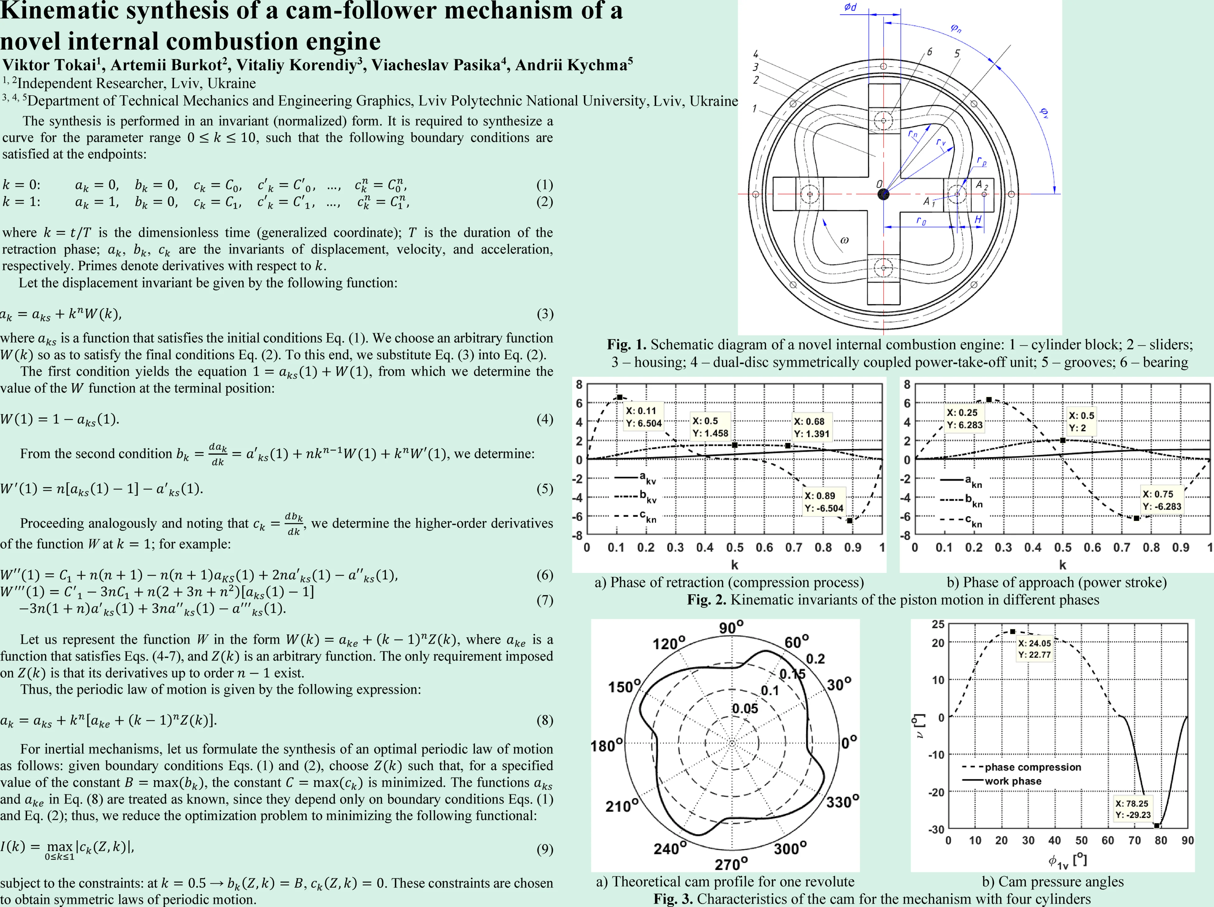
In the patents [13] and [14], the authors have proposed a novel internal combustion engine comprising a cylinder block 1 in which the sliders 2 move (Fig. 1). The cylinder block is stationary and rigidly connected to a housing 3 that accommodates a dual-disc symmetrically coupled power-take-off unit 4 with grooves 5. The cylinders 1 are arranged between the two discs of the power-take-off unit 4. A shaft (pin) is rigidly attached to each slider; a bearing 6 is mounted on the end of this pin and rolls within the groove. The pistons together with the groove form a cam mechanism that dispenses with a separate tappet and roller. This structural solution – i.e., replacing the rod and rollers with pins fitted with end bearings – simplifies the design and eliminates drawbacks of earlier configurations associated with excessive piston mass (inertial overloading). The cam-equipped disc 4 is driven by an external source (starter). When rotating through the retraction phase angle , the cams move the slider from position to position (compression phase). As the system approaches position , combustion occurs, and the generated gases drive the sliders back from to ; during this power stroke, the cams rotate through the approach phase angle . Disc 4 is rigidly connected to the cams and rotates about the center of rotation . The minimum radial distance of the sliders from the center is , and the slider stroke is . Positions and are the extremes (Bottom Dead Center (BDC) and Top Dead Center (TDC)).
The preferred number of cylinders is four, which means that during one revolution of the discs, four cylinders deliver a power stroke. The proposed internal combustion engine is compact, provides high torque and specific power, and compares favorably with inline and V-type engines because it does not require complex theoretical analysis and mechanical balancing. The groove profile for the retraction (compression) phase has been synthesized so that piston motion attains zero acceleration at the phase boundaries and exhibits a quasi-constant-velocity interval around the midpoint of the kinematic cycle. This eliminates end-of-phase shocks and better prepares the fuel-air mixture for combustion. For the approach phase, the profile is synthesized according to a sinusoidal law, which ensures zero inertial loading at the phase boundaries.
Fig. 1Schematic diagram of a novel internal combustion engine: 1 – cylinder block; 2 – sliders; 3 – housing; 4 – dual-disc symmetrically coupled power-take-off unit; 5 – grooves; 6 – bearing
2.2. Synthesis of a periodic motion law
The cam profile comprises two phases: retraction and approach. During the retraction phase, the fuel-air mixture is compressed; during the approach phase, the power stroke occurs. The cam profile for the retraction phase is synthesized to produce slider motion with a quasi-constant-velocity segment near the middle of the kinematic cycle. To reduce inertial loading on the slider, the slider acceleration is zero at the outer boundaries (endpoints) of both phases.
The synthesis of a periodic law of motion is reduced to the classical mathematical problem of constructing a curve that passes through two prescribed points. Such curves are most commonly represented by polynomial functions [3]-[8]; thus, the synthesis amounts to determining, from a system of algebraic equations, the coefficients of the polynomial that describes the curve being synthesized. The number of equations equals the number of conditions imposed on the curve at the specified points. This system has a unique solution, yielding a single curve from the multitude of possible ones. If additional non-discrete (i.e., non-pointwise) conditions are imposed on the curve, this approach does not produce the desired result. Unlike existing methods, the proposed approach not only enables the synthesis of a curve under discrete conditions, but also allows one to formulate and solve the problem of selecting a curve for which the specified extremal parameters attain minimum values.
The synthesis is performed in an invariant (normalized) form. It is required to synthesize a curve for the parameter range , such that the following boundary conditions are satisfied at the endpoints:
where is the dimensionless time (generalized coordinate); is the duration of the retraction phase; , , are the invariants of displacement, velocity, and acceleration, respectively. Primes denote derivatives with respect to .
Thus, adopting Eqs. (1) and (2), we impose boundary conditions on the law of motion.
Let the displacement invariant be given by the following function:
where is a function that satisfies the initial conditions Eq. (1). We choose an arbitrary function so as to satisfy the final conditions Eq. (2). To this end, we substitute Eq. (3) into Eq. (2).
The first condition yields the equation , from which we determine the value of the function at the terminal position:
From the second condition , we determine:
Proceeding analogously and noting that , we determine the higher-order derivatives of the function W at ; for example:
Let us represent the function W in the form , where is a function that satisfies Eqs. (4-7), and is an arbitrary function. The only requirement imposed on is that its derivatives up to order exist.
Thus, the periodic law of motion is given by the following expression:
The resulting periodic law of motion has clear advantages over polynomial laws [3]-[8]. As can be seen, the expression includes an arbitrary function subject only to the requirement that its derivatives up to order exist. By selecting this arbitrary function appropriately, we gain an additional degree of freedom to shape the law itself. Moreover, all basic periodic motion laws can be recovered as special cases of the proposed formulation.
For inertial mechanisms, let us formulate the synthesis of an optimal periodic law of motion as follows: given boundary conditions Eqs. (1) and (2), choose such that, for a specified value of the constant , the constant is minimized. The functions and in Eq. (8) are treated as known, since they depend only on boundary conditions Eqs. (1) and Eq. (2); thus, we reduce the optimization problem to minimizing the following functional:
subject to the constraints: at → , . These constraints are chosen to obtain symmetric laws of periodic motion.
3. Results and discussion
3.1. Numerical modeling of the kinematic invariants of the piston motion
To carry out the numerical minimization of functional Eq. (9), let us represent (expand) as a series:
where are undetermined coefficients and are preselected functions. Then, functional Eq. (9) depends only on the coefficients , i.e., . For practical purposes, it is sufficient to truncate the series at .
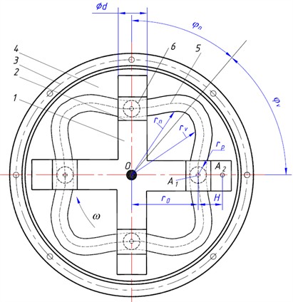
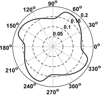
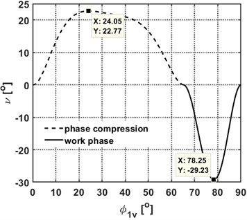
As a result of minimizing functional Eq. (9), a periodic law of motion was obtained that contains a quasi-constant-velocity segment over 39 % of the kinematic cycle, within a 5 % tolerance (Fig. 2(a)). At the boundaries of the synthesized law, the slider acceleration is zero, which ensures the absence of end-of-phase soft impacts. The kinematic invariants of the slider during the retraction phase are:
During the approach phase, the cam profile can, in principle, be arbitrary. We adopt the simplest cycloidal periodic motion law – the sinusoidal law (Fig. 2(b)) [1], [2], which ensures zero slider acceleration at the phase boundaries:
At the transition point from the retraction phase to the approach phase, the slider acceleration is also zero.
The synthesized periodic motion law (Fig. 2(a)) compares favorably with the well-known sinusoidal law (Fig. 2(b)). The acceleration constants for the two laws are practically identical, and . For the synthesized law, the velocity constant is , which is 31 % lower than the sinusoidal law’s 2.
Fig. 2Kinematic invariants of the piston motion in different phases
a) Phase of retraction (compression process)

b) Phase of approach (power stroke)
3.2. Synthesis of the cam profile for the working (power) and return (idle) strokes
The cam mechanism under consideration is non-classical: it has no separate tappet; nevertheless, its synthesis can be performed using the standard, well-established methodology [2].
The radius vector of the theoretical cam profile in the retraction phase is given by:
and in the approach phase:
The actual (dimensional) values of the slider’s kinematic characteristics in the retraction and approach phases are calculated from the following expressions:
where , are the durations of the retraction and approach phases, respectively, and is the total time of both phases.
The linear velocity of the roller axis in the retraction phase and in the approach phase are calculated from the following expressions:
The pressure angle in cam mechanisms governs efficiency and the propensity of the cam-follower pair to jam. For the mechanism under study, the pressure angles are computed using the standard relations for a radial (central) cam with a translating follower [1], [2]:
where , are the derivatives of the radius vector with respect to the dimensionless variable .
In the course of the study, we examined phase-duration splits between the retraction (pressurization/compression) phase and the approach (discharge/exhaust) phase ranging from 70°/20° to 60°/30°. The experimental model was implemented with a 65°/25° split, and with the following parameters [13], [14]: 45 mm, 0.01 s, 65°, 25°, 140 mm, 12.5 mm, 50 mm, 0.67 kg (the reduced mass of the piston).
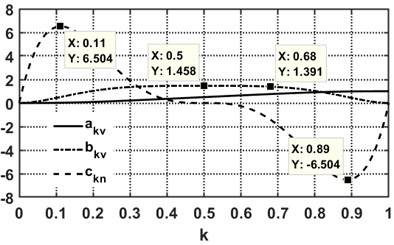
Fig. 4(a) shows the theoretical cam profile for a four-cylinder mechanism. The transition from the compression phase to the power stroke is characterized by a rapid decrease in the profile’s radius vector, which may raise concerns about the operability of the cam mechanism. However, the pressure angles plotted in Fig. 5 indicate that their maximum values lie within permissible limits (typically up to 30° [2]), confirming that the cam mechanism is fully operable.
Fig. 3Characteristics of the cam for the mechanism with four cylinders
a) Theoretical cam profile for one revolute
b) Cam pressure angles
4. Discussion of the results obtained
Sensitivity to design parameters. A qualitative sensitivity scan was performed for the following key non-dimensional and sizing parameters:
1) Radius ratio . Increasing the minimum cam radius to stroke ratio reduces the maximum pressure angle and follower side load at the expense of a larger cam envelope. The S-V-A shapes remain similar in normalized coordinates; dimensional peaks scale down with larger .
2) Plateau fraction . Enlarging the quasi-constant-velocity segment widens the interval of low velocity gradient and suppresses mid-stroke ripples. Curvature changes shift toward the phase boundaries; enforcing zero acceleration at the transitions limits end-effects. Excessive may increase local curvature near the joins, which should be checked against contact stress criteria.
3) Phase split . The retraction-to-approach split moves the locations of kinematic extrema. More time allocated to the process-critical phase lengthens its constant-speed span without raising endpoint peaks, provided pressure-angle limits are respected. The demonstrated split remains inside the admissible envelope.
4) Speed . Angular speed scales dimensional velocity, acceleration, and jerk linearly, but does not change normalized constants. Bearing selection, lubrication regime, and thermal load should therefore be verified using dimensional S-V-A levels for the intended .
5) Follower mass and compliance. Higher reduced mass increases inertial forces at a given acceleration profile; compliant elements in the transmission can filter jerk but may introduce resonances. For high-rate operation, pairing the synthesized profile with adequate damping and stiffness helps maintain contact and limit peak forces.
These trends provide practical levers for balancing compactness, efficiency, and durability: governs pressure-angle headroom, sets process smoothness, the phase split tailors where peaks occur, and fixes dimensional load levels.
Comparison with literature data. This study synthesizes a non-symmetric motion program that includes a mid-stroke quasi-constant-velocity segment and zero-acceleration boundary conditions at phase transitions. In cam and slider design, common reference profiles are sinusoidal, cycloidal, and polynomial families such as 3-4-5. Relative to a sinusoidal law of equal stroke and duration, the present program reduces the mid-stroke velocity gradient while keeping comparable peak acceleration. This aligns with reported links between lower velocity ripple and reduced tool-force variation and contact heating in reciprocating mechanisms [1-4]. Compared with cycloidal profiles, the proposed law preserves smooth endpoint behavior while shifting kinematic activity away from the mid-stroke, which is advantageous when constant process speed is desired during a critical segment of motion [2, 5]. Against 3-4-5 polynomials, the synthesized law achieves similar endpoint smoothness with a more explicitly tunable plateau fraction, allowing a direct trade-off between constant-speed span and curvature concentration near transitions [3, 6]. Pressure-angle checks remain within ranges broadly considered admissible for translating followers in compact mechanisms, which is consistent with published feasibility criteria [7-12]. Overall, the normalized kinematic constants and pressure-angle envelopes observed here are consistent with literature trends for low-vibration, durability-oriented cams, while the explicit plateau provides an added degree of freedom for process control.
Engineering interpretation and design implications. The synthesized retraction law contains a mid-stroke quasi-constant-velocity segment. Physically, this flattens piston speed when the trapped charge is being compressed, which reduces pressure rise rate irregularities, lowers instantaneous inertial force variation on the slider–bearing pair, and eases mixture preparation. Enforcing zero acceleration at both phase boundaries removes end-of-stroke inertial “snaps,” so contact forces and seating impacts are milder and lubrication is more stable. Relative to a sinusoidal baseline, the present law preserves a similar peak acceleration constant while lowering the velocity constant. This means comparable peak inertial demand but smaller mid-stroke velocity gradients, which helps reduce wear and energy loss in the cam-follower contact. Pressure angles remain within common admissible limits for translating followers, which indicates low risk of side-load jamming and acceptable efficiency. Together these traits explain, in practical terms, why the proposed motion law is attractive for cam-driven reciprocators in engines and related machinery.
5. Conclusions
An invariant formulation for cam-driven slider motion was developed, introducing an arbitrary shaping function that enables both exact satisfaction of endpoint constraints and optimization of peak acceleration. The optimized periodic law of motion includes a quasi-constant-velocity segment spanning approximately 39 % of the compression phase with ±5 % tolerance; accelerations vanish at the phase boundaries, mitigating soft impacts. When paired with a sinusoidal approach law, the synthesized retraction law preserves comparable acceleration constants (6.504 vs. 6.283) while lowering the velocity constant by approximately 31 % (1.458 vs. 2.000), indicating reduced inertial loading. Complete cam profiles for working and return strokes were obtained, and pressure-angle analysis across tested phase splits (e.g., 70°/20° to 60°/30°) stayed within typical admissible limits for translating followers, confirming mechanism feasibility.
The framework yields closed-form kinematic invariants and dimensional kinematics for piston and roller, enabling bearing-speed estimation needed to target hydrodynamic lubrication regimes. The approach is compact and implementable (series truncated to four terms) and is readily extensible to multi-objective designs (e.g., co-minimizing jerk and contact stress) and to alternative motion bases (e.g., spline/NURBS) in future work.
Comprehensive experimental validation of the proposed motion law, including prototype fabrication, bench tests of kinematics and pressure-angle limits, and endurance measurements, is underway, and detailed results with test rig description and uncertainty analysis will be presented in subsequent publications.
References
-
R. L. Norton, “Cam Design and Manufacturing Handbook, 2nd ed.,” Industrial Press, New York, NY, USA, 2009.
-
R. L. Norton, “Design of Machinery: An Introduction to the Synthesis and Analysis of Mechanisms and Machines, 6th ed.,” McGraw-Hill Education, New York, NY, USA, 2020.
-
E. Sandgren and R. L. West, “Shape optimization of cam profiles using a B-spline representation,” Journal of Mechanisms, Transmissions, and Automation in Design, Vol. 111, No. 2, pp. 195–201, Jun. 1989, https://doi.org/10.1115/1.3258983
-
R. H. Bravo and F. W. Flocker, “Optimizing cam profiles using the particle swarm technique,” Journal of Mechanical Design, Vol. 133, No. 9, p. 09100, Sep. 2011, https://doi.org/10.1115/1.4004587
-
S. Acharyya and T. K. Naskar, “Fractional polynomial mod traps for optimization of jerk and hertzian contact stress in cam surface,” Computers and Structures, Vol. 86, No. 3-5, pp. 322–329, Feb. 2008, https://doi.org/10.1016/j.compstruc.2007.01.045
-
M. Mandal and T. K. Naskar, “Introduction of control points in splines for synthesis of optimized cam motion program,” Mechanism and Machine Theory, Vol. 44, No. 1, pp. 255–271, Jan. 2009, https://doi.org/10.1016/j.mechmachtheory.2008.01.005
-
Nguyen and T. T. N., “Motion design of cam mechanisms by using non-uniform rational B-Spline,” RWTH Aachen University, Aachen, Germany, 2018.
-
L. K. Sahu, O. P. Gupta, and M. Sahu, “Design of cam profile using higher-order B-Spline,” International Journal of Innovative Science, Engineering and Technology, Vol. 3, No. 2, pp. 327–335, Feb. 2016.
-
M. Todorović, G. Marković, R. Bulatović, M. Bošković, and M. Savković, “Cam displacement curve optimization for minimal jerk using search and rescue optimization algorithm,” Proceedings of the Institution of Mechanical Engineers, Part C: Journal of Mechanical Engineering Science, Vol. 238, No. 21, pp. 10332–10343, Jul. 2024, https://doi.org/10.1177/09544062241260566
-
B. Hu, C. Zhou, H. Wang, and L. Yin, “Prediction and validation of dynamic characteristics of a valve train system with flexible components and gyroscopic effect,” Mechanism and Machine Theory, Vol. 157, p. 104222, Mar. 2021, https://doi.org/10.1016/j.mechmachtheory.2020.104222
-
A. Rivola, M. Troncossi, G. Dalpiaz, and A. Carlini, “Elastodynamic analysis of the desmodromic valve train of a racing motorbike engine by means of a combined lumped/finite element model,” Mechanical Systems and Signal Processing, Vol. 21, No. 2, pp. 735–760, Feb. 2007, https://doi.org/10.1016/j.ymssp.2006.06.004
-
R. L. Norton, “DYNACAM User Manual,” Norton Associates Engineering, Norfolk, MA, USA, 2006.
-
V. N. Tokai and A. V. Burkot, “Method for operating an internal combustion engine,” (in Ukrainian), Ukrainian Patent UA 156790, 2024.
-
V. N. Tokai and A. V. Burkot, “Internal combustion engine,” (in Ukrainian), Ukrainian Patent UA 157599, 2024.
About this article

The authors have not disclosed any funding.
The datasets generated during and/or analyzed during the current study are available from the corresponding author on reasonable request.
The authors declare that they have no conflict of interest.
