Abstract
A methodology has been proposed for calculating the force loading of anchor bandages of locomotive traction electric motors from the action of external dynamic factors, which makes it possible to determine dynamic stresses in each section of the anchor bandage along its entire length, depending on the operating modes of the traction electric motor, taking into account its design features and real operating conditions. It has been established that the most significant influence on the fluctuations of the armature shaft of traction electric motors of diesel locomotives is exerted by dynamic influences from the collision of wheels with joints and unevenness of the rail track, as well as from errors in the manufacture of the serrated broadcast (gears). The supposed economic effect from the creation of new glass bandage designs for the anchors of traction electric motors of diesel locomotives of the 2TE10M series is estimated at approximately 10.92 million soums for one such diesel locomotive. It is recommended to continue these studies in order to develop and justify rational geometric parameters of a new design of the anchor glass bandages of a traction electric motor with increased fatigue strength.
Highlights
- A method for calculating the force loading of anchor bandages of locomotive traction electric motors from the action of external dynamic factors has been developed, taking into account real operating conditions and design features of the traction electric motor.
- The proposed methodology for calculating anchor bandages makes it possible to determine dynamic stresses in each section of the anchor bandage along its entire length, depending on the operating modes of the traction electric motor.
- The economic effect from the introduction of the proposed (new) design of the glass bandage for the anchors of traction electric motors of diesel locomotives with traction electric motors of the ED-118B type, will amount to approximately 910 thousand soums.
1. Introduction
The main task of railway transport is to universally meet the needs for the transportation of goods and passengers on sections of railways of varying complexity.
The efficiency of existing and newly-built locomotives directly depend on the compliance of their traction and energy characteristics with operating conditions, and this is primarily determined by the parameters of the traction electric motor, as the most stressed unit of the energy transmission.
The above puts forward certain requirements for improving the designs of locomotive components [1-3], including traction electric motors through a higher use of active materials, taking into account an increase in rotation speed with a corresponding decrease in the specific mass of these engines, as well as the improvement of the operating locomotive fleet through factory repairs and modernization of energy-consuming systems, which include traction power circuits and auxiliary equipment that ensures their trouble-free and uninterrupted operation.
Works [4-13] are devoted to the development of theoretical foundations for design and methods for calculating the strength of various components of traction electric motors.
An analysis of these works shows that they consider methods for calculating individual components and parts of wheel-motor units of diesel locomotives, including the bandages for fastening the frontal parts of the anchors of traction electric motors. However, these methods relate to the designs of metal bandages and glass tape bandages and do not fully take into account operating conditions, taking into account the stress distribution along the length of the bandage.
This article is devoted to theoretical research on the justification of the force loading of anchor bandages of traction electric motors from the action of external dynamic factors encountered along in the route of rolling stock. The premise for this was research [14-21] into the study of the power loading of various units of the locomotive undercarriage.
2. Objects and methods of research
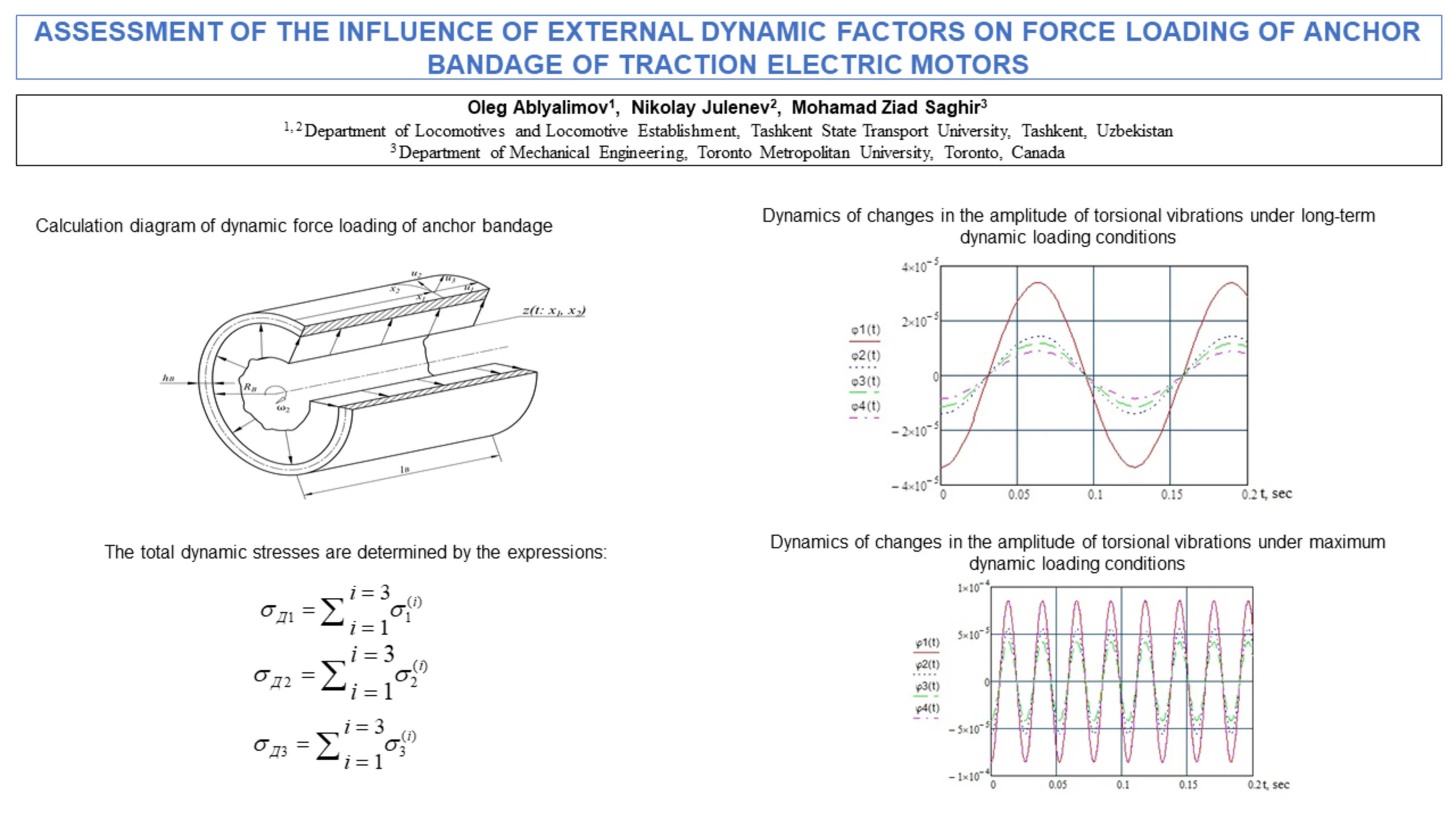
In operation, the traction electric motor armature operates under extremely difficult conditions. It is subject to bending from the forces of magnetic attraction to the poles, gear reaction from transmitted torques, gear errors, as well as forces resulting from the interaction of the wheel-motor units with the rail base. The above force factors also influence the stress state of the anchor shrouds due to the dynamic addition to the centrifugal forces acting on the masses of the frontal parts and the shroud itself as a whole.
In order to determine the amplitude and frequency of the dynamic forces acting on the anchor shroud of traction electric motors of diesel locomotives 2TE10M, we used the data obtained in works [1, 2], which presented the results of analytical and experimental studies of vibrations of the armature shaft of these traction electric motors.
These works show that the most significant influence on shaft vibrations is exerted by dynamic influences from the collision of wheels with joints, unevenness of the rail track and manufacturing errors in the circumferential pitches of the pinion and gear wheel.
To solve the problem of dynamic loading of the rear anchor bandage, as the most loaded due to the cantilever of the frontal parts, the following assumptions were made.
1. The bandage is a cylindrical shell rotating at a constant speed with thickness and radius (and ). Taking into account the last relation, the moment-free theory [3, 21] is applicable to such a shell, which is a simplified version of the general moment theory of shell calculations, in which is neglected the influence of bending and torsional moments, as well transverse forces on the stress-strain state.
2. The bandage is subject to an external distributed dynamic centrifugal load from the mass of the bandage and the frontal parts, caused by bending vibrations of the traction electric motor armature shaft from the interaction of the wheel-motor unit with irregularities and joints of the rail track and from systematic errors (inaccuracies) in the gear transmission of the traction reducer.
3. The bending rigidity of the frontal parts of the winding is not taken into account in the safety factor of the bandage.
4. We neglect the resistance to elastic vibrations of the anchor bandage in order to somewhat simplify the solution of the problem posed by the safety factor of the specified bandage.
5. Steady-state forced vibrations of the anchor bandage are considered.
The design diagram of the bandage in the form of a cylindrical shell with the ratio in accordance with the above assumptions is shown in Fig. 1.
Fig. 1Calculation diagram of dynamic force loading of anchor bandage

The coordinates on the middle surface of the shell are coordinates along the generatrix and arc length in the circumferential direction [4]. The displacements of the points of the middle surface along the coordinate lines , and along the normal are indicated, respectively, by ; and .
Let us determine the potential energy of shell deformations [22], namely:
where , , – the deformation components are respectively equal:
Taking into account relations Eq. (2), the potential energy of the shell, expressed through the displacement of points on its middle surface, will be written in the form:
The kinetic energy of the shell is determined by the expression [4]:
The work of centrifugal forces in accordance with [4] can be written in the form:
According to Hamilton’s principle, it is necessary to find the stationary value of the functional for the known conditions imposed on variations according to [4, 23], that is:
3. Results and their discussion
After substituting expressions for kinetic, potential energy and work of centrifugal forces into Eq. (6), we obtain the following analytical expression for the Lagrange function of the considered (studied) shell, namely:
In accordance with the well-known provisions of the calculus of variations [24, 25], the system of functions ; and , implementing the principle of least action, must satisfy the system of partial differential equations ( 1, 2, 3), that is:
After substituting the expression for the Lagrange Eq. (7) into Eq. (8), the following system of shell vibration equations is obtained:
where – external dynamic load normal to the surface of the anchor bandage, per unit surface of the shell.
As explained above, the dynamic load is a centrifugal force caused by bending vibrations of the armature shaft of a traction electric motor due to the interaction of wheels with irregularities and joints of the rail track, and systematic errors in the circumferential pitch of the gear reducer.
Therefore, the dependence of the external dynamic load on time and coordinates is taken in the form:
where – coefficient of reduction of the mass of the frontal parts to the anchor bandages; – coefficient taking into account the distribution of centrifugal forces along the length of the anchor bandages. This assumption is due to the fact that the frontal parts are secured in the grooves with wedges; – coefficient taking into account the distribution of centrifugal forces along the perimeter of the anchor bandage caused by the eccentricity of the anchor shaft; – dynamic deflection of the armature shaft from the action of the -th disturbing factor; – frequency of forced bending vibrations of the armature shaft under the influence of the -th disturbing factor; and – integers.
The solution to the system of Eq. (9) for forced oscillations, due to their linearity, was obtained by superposition of solutions for any -th disturbing factor, each of which was found in the form:
Using Eq. (11), the stress values in the middle surface are determined for each -th dynamic force factor:
The total dynamic stresses are determined by the expressions:
The prerequisite for the next stage of research was also the unconditional “importance” of the anchor bandage for traction electric motors operating under difficult conditions and at high speeds, since reliable fastening of the armature winding with a bandage is critical for preventing premature emergency failures that occur during the movement of rolling stock.
In addition, despite the fact that the presented research methodology provides a completely reliable assessment of the parameters of the force loading of the anchor bandages of traction electric motors from the action of external dynamic factors encountered along the route of the rolling stock, it should be noted that additional uncertainty estimates and limitations, the data associated with the numerical study of torsional vibrations of the masses of the wheel-motor unit of the 2TE10M diesel locomotive, in which the traction electric motor is the central unit, will make it possible to obtain the dynamics of changes in the amplitudes of torsional vibrations of the traction electric motor armature shaft under various dynamic loading conditions.
Fig. 2Dynamics of changes in the amplitude of torsional vibrations under long-term dynamic loading conditions
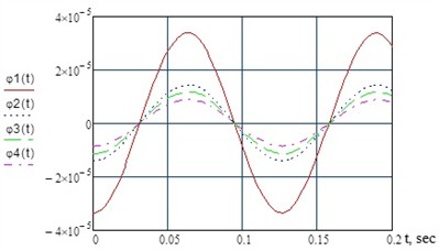
Fig. 3Dynamics of changes in the amplitude of torsional vibrations under maximum dynamic loading conditions
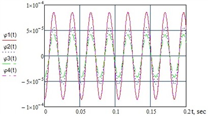
Numerical studies were carried out in the MATHCAD 15 programming environment, based on a dynamic model of torsional vibrations in the wheel-motor unit of a similar diesel locomotive of the UzTE16M series [26]. To implement the numerical studies, two main dynamic loading modes were adopted: long-term and maximum loading modes at the rotation frequency of the traction motor anchor, respectively 476 rpm and 2290 rpm.
The results of numerical calculations of torsional vibrations in the wheel-motor unit of the studied 2TE10M diesel locomotive are shown in Fig. 2 and Fig. 3, where the amplitudes of torsional vibrations are indicated for the following sections: – armature shaft; – gears; – toothed wheels; – wheelset axles.
An analysis of the results of numerical studies showed that with an increase in the rotation frequency of the anchor of the ED-118B traction electric motor of the 2TE10M series diesel locomotive, the amplitude of torsional oscillations of various masses of the studied wheel-motor unit increases, while the period of their oscillations decreases.
4. Conclusions
Based on the results of the study, the goal of the work was achieved and the following general conclusions and proposals were formulated:
1) Based on an analysis of existing methods for calculating the strength of bandages for fastening frontal parts for windings of anchors of electric machines, a method for calculating the force loading of anchor bandages of locomotive traction electric motors from the action of external dynamic factors has been developed, taking into account real operating conditions and design features of the traction electric motor.
2) The proposed methodology for calculating anchor bandages, in contrast to the known ones, makes it possible to determine dynamic stresses in each section of the anchor bandage along its entire length, depending on the operating modes of the traction electric motor.
3) The economic effect from the introduction of the proposed (new) design of the glass bandage for the anchors of traction electric motors of diesel locomotives, obtained by reducing manufacturing costs and correspondingly increasing the operational reliability of one traction electric motor of the ED-118B type, will amount to approximately 910 thousand soums.
4) The main direction of research here is the substantiation of rational design parameters of glass bandages taking into account the conditions of their fatigue strength, based on the analytical and graphical dependencies obtained by the authors of the articles, by performing calculations using a computer, as well as the development of a new design of an anchor glass bandage for a traction electric motor with increased strength and manufacturability, which provides for the use of standard equipment in its manufacture.
References
-
G. V. Strokov, “Improving the design of anchor bands for traction electric motors of locomotives,” Moscow, 1999.
-
A. D. Glushchenko and H. H. Tulchinskaya, “Substantiation of the parameters of the structures of high-strength terminals for magnetic systems of electric motors of diesel locomotives,” The works of Tashiit, No. 146, pp. 6–12, 1998.
-
V. K. Volkov and A. G. Suvorov, Improving the Operational Reliability of Traction Engines. Moscow: Transport, 2003.
-
H. H. Tulchinskaya, “Method of calculating voltages in wires and terminals of pole windings of traction electric motors of locomotives,” The works of Tashiit, No. 166, pp. 22–30, 2002.
-
I. P. Gordeev and E. M. Tarasov, “On the issue of defection of anchors of traction electric motors,” (in Russian), Izvestiya of Higher Educational Institutions. The North Caucasus Region. Technical Sciences, No. 2, pp. 57–63, 2006.
-
I. P. Gordeev, “On the issue of the organization of selective control in the production of electric machines,” Bulletin of Electrical Engineers of Railway Transport, pp. 333–338, 2003.
-
A. S. Kosmodamiansky, “Measurement and regulation of temperature of windings of traction electric machines of locomotives,” RGOTUPS, 2002.
-
V. I. Kiselev and G. V. Strokov, “Methods of calculating anchor bands of traction electric motors of transport electric machines for strength,” TSNIITEI MPS, Moscow, 1997.
-
A. D. Glushchenko and V. I. Yushko, Dynamics of Traction Electric Motors of Diesel Locomotives. Tashkent: Fan, 1990.
-
S. M. Ovcharenko, O. V. Balagin, and D. V. Balagin, “Increasing the efficiency of the cooling system of diesel locomotives in operation,” Journal of Transsib Railway Studies, Vol. 27, No. 1, pp. 27–34, 2017.
-
S. M. Ovcharenko, I. S. Ring, and S. S. Ovcharenko, “Study of temperature conditions of operation of cooling systems of diesel locomotives during operation,” Journal of Transsib Railway Studies, Vol. 50, No. 2, pp. 116–123, 2022.
-
S. Abdurasulov, N. Zayniddinov, and K. Kosimov, “Strength requirements for locomotive load-bearing structures: a literature review,” International Scientific Journal “Engineer”, Vol. 3, No. 1, pp. 14–18, 2025.
-
S. V. Myamlin, O. Lunys, and L. O. Neduzha, “Peculiarities of running gear construction of rolling stock,” Science and Transport Progress, No. 3(69), pp. 130–146, Jun. 2017, https://doi.org/10.15802/stp2017/104824
-
O. Ablyalimov, “To the diagnostic technique of support-returning devices and of the spring suspension of diesel locomotives,” in E3S Web of Conferences, Vol. 460, p. 10008, Dec. 2023, https://doi.org/10.1051/e3sconf/202346010008
-
O. Ablyalimov, “To the substantiation of charge air parameters on different operating modes of diesel engines of diesel locomotives,” in E3S Web of Conferences, Vol. 460, p. 06010, Dec. 2023, https://doi.org/10.1051/e3sconf/202346006010
-
O. Ablyalimov, “Justification of force loading parameters of screw cylindrical springs for spring suspension of locomotives,” in 6th International Scientific Conference Construction Mechanics, Hydraulics and Water Resources Engineering (CONMECHYDRO 2024), Vol. 3286, p. 060006, Jan. 2025, https://doi.org/10.1063/5.0279718
-
O. Ablyalimov, G. Bakyt, N. Tursunov, U. Safarov, and Y. Baubekov, “Research of heat transfer processes in motor-axial bearings of traction electric motors of diesel locomotives,” Vibroengineering Procedia, Vol. 58, pp. 264–270, May 2025, https://doi.org/10.21595/vp.2025.24955
-
O. Ablyalimov and M. Z. Saghir, “Analytical studies to justify the design parameters of springs combining the qualities of fluctuations damper,” in International Conference on Thermal Engineering, 2025.
-
O. Ablyalimov and M. Z. Saghir, “On the question of calculation methodology of springs of spring suspension of rolling stock for strength,” in International Conference on Thermal Engineering, Vol. 1, No. 1, 2025.
-
O. Ablyalimov and M. Z. Saghir, “Experimental studies of characteristics of springs with composite section on models from polymer materials,” in International Conference on Thermal Engineering, 2025.
-
V. Y. Panovko, Strength, Stability, Fluctuations: a Reference Book. Moscow: Nauka, 1976.
-
A. T. Filippov, Oscillations of Deformable Systems. Moscow: Mechanical Engineering, 1975.
-
G. Korn and T. Korn, Handbook of Mathematics (For Researchers and Engineers). Moscow: Nauka, 1977.
-
B. P. Rodin, Calculus of Variations: Textbook. St. Petersburg: Baltic State Technical University Voenmekh named after D.F. Ustinov, 2017.
-
A. V. Panteleev, Calculus of Variations in Examples and Problems. Moscow: Graduate School, 2006.
-
S. Fayzibaev, A. Avdeeva, S. Mamaev, and D. Nigmatova, “Modeling of torsional vibrations of the wheel-motor unit of the uzte16m diesel locomotive,” Universum: Technical sciences, Vol. 97, No. 5-5, Apr. 2022, https://doi.org/10.32743/unitech.2022.97.4.13387
About this article

The authors have not disclosed any funding.
The datasets generated during and/or analyzed during the current study are available from the corresponding author on reasonable request.
The authors declare that they have no conflict of interest.
