Abstract
This paper develops and evaluates a cam-actuated variable-length crank for reciprocating frame-saw drives equipped with springs placed perpendicular to the slider path. An invariant formulation is used to synthesize a periodic slider motion in which the spring force projected along the stroke cancels the slider inertia force. This yields a second-order differential equation with a non-dimensional stiffness parameter for the perpendicular-spring layout; the corresponding cam (variable crank length) is then recovered from the synthesized law of motion. Numerical studies for a representative frame-saw geometry confirm that the proposed synthesis eliminates inertial loading of the slider and produces a pronounced quasi-constant-velocity segment in mid-stroke (about 40 % of the stroke within a 5 % tolerance). The theoretical cam profile is well approximated by an ellipse (semi-axes 0.4996 and 0.4106 in non-dimensional form) with a maximum radial deviation of 0.00235; the associated pressure angles are about 13°, i.e., comfortably within typical limits. These results demonstrate that combining a cam-modulated variable crank length with a perpendicular-spring environment enables kinematic balancing with feasible pressure angles and motion shaping favorable for wood and stone cutting.
Highlights
- An invariant synthesis for a cam-actuated variable-length crank with perpendicular springs balances slider inertia forces. This integrates dynamic balancing directly into the kinematic design to reduce unbalanced loads in frame-saw drives.
- The synthesized motion law produces a quasi-constant-velocity segment covering 40% of the slider stroke within ±5% tolerance. This enables uniform cutting conditions, potentially reducing tool-force variation and improving surface finish.
- The theoretical cam profile is well approximated by an ellipse (semi-axes 0.4996 and 0.4106) with a max radial deviation of 0.00235. Pressure angles remain near 13°, staying well within admissible limits for efficient power transmission.
1. Introduction and methodology
Reciprocating frame saws remain essential for wood and stone processing, yet their main-motion drives must meet conflicting targets: high removal in the power stroke, gentle reversal near dead points, low velocity ripple, and bounded inertial forces. Evidence across vibro-impact and crank-excited systems shows that excitation shape – not only stiffness – governs dynamic loads and efficiency [1-4]. In frame-saw applications, time-varying feed-drive dynamics amplify velocity fluctuations and shift resonances, which motivates motion laws that temper excitation through the cut [5]. Process-level studies (e.g., reciprocating-swing motion in diamond frame saws) link tailored kinematics to chip thickness and force benefits [6], while narrow-kerf gang sawing highlights lateral force components as a key source of geometric error, emphasizing control of transients near reversals [7]. Together, these results indicate that shaping the reciprocation law can reduce wear, force spikes, and accuracy loss.
Two strands of synthesis are especially relevant to a cam-actuated variable-length crank: inverse (motion-driven) cam design directly enforces a desired follower trajectory and can reduce torque ripple relative to forward methods [8], and approximate dwell near dead points can be realized with multi-loop linkages to achieve “slow-near-dead-point / fast-through-cut” motion [9]. Related concepts in engines modulate effective crank radius via eccentrics, paralleling crank-length variation achievable with a cam-modulated sleeve, though without the explicit dwell and force shaping of cams [10]. A second thread concerns elastic-energy management: embedding springs in slider-crank transmissions can exploit resonance, cut peak joint forces, and lower input torque [11, 12]. Finally, perpendicular (orthogonal) spring layouts decouple along-stroke and transverse stiffness, enable high-static-low-dynamic or quasi-zero-stiffness behavior, and buffer reversal transients; demonstrations span six-DOF isolators and orthogonal modules with tunable stiffness [13-15]. These insights support a reciprocation law shaped by inverse cam synthesis and aided by perpendicular springs.
While the literature provides accurate models of sawing and feed dynamics [5]-[7], motion-law synthesis via cams and multi-loop linkages [4], [8], [9], concepts for modulating effective crank radius [10], and elastic architectures enabling HSLDS/QZS behavior [11]-[15], there is still no integrated treatment of a cam-actuated variable-length crank tailored to frame-saw kinematics with a perpendicular-spring environment that couples kinematic synthesis and dynamic response. This paper continues the authors previous research presented in [16] and addresses the above-mentioned gap by deriving the kinematics of a cam-modulated telescoping (variable-length) crank that enforces extended dwell near dead points and a high-velocity cutting segment; and formulating a synthesis procedure that co-selects cam law, crank-length schedule, and spring parameters to meet constraints on pressure angle, peak force, and velocity ripple. The resulting methodology targets lower cutting-direction force spikes, reduced return-stroke losses, and improved dimensional accuracy relative to constant-throw drives.
The major contributions and novelty of the present research are as follows. This work: 1) derives an invariant synthesis for a cam-actuated variable-length crank with perpendicular springs that balances slider inertia with projected spring force; 2) produces a motion law with a mid-stroke quasi-constant-velocity segment of about 40 % within ±5 %; 3) recovers a manufacturable cam whose pressure angle does not exceed 13° and is well approximated by an ellipse with small radial error; 4) provides a practical stiffness selection rule using non-dimensional parameters of the actuating mechanism.
The methodology of research consists in the following. We prescribe a periodic slider motion that equalizes the projected spring force and inertia along the stroke, yielding a second-order ordinary differential equation for the displacement vs. cam angle. Solving this equation gives the motion law; the variable crank length (theoretical cam) follows analytically. We then compute pressure angle and manufacturability metrics and compare against a constant-throw baseline.
2. Synthesis of the variable crank length in the combined crank-slider mechanism with perpendicular spring placement
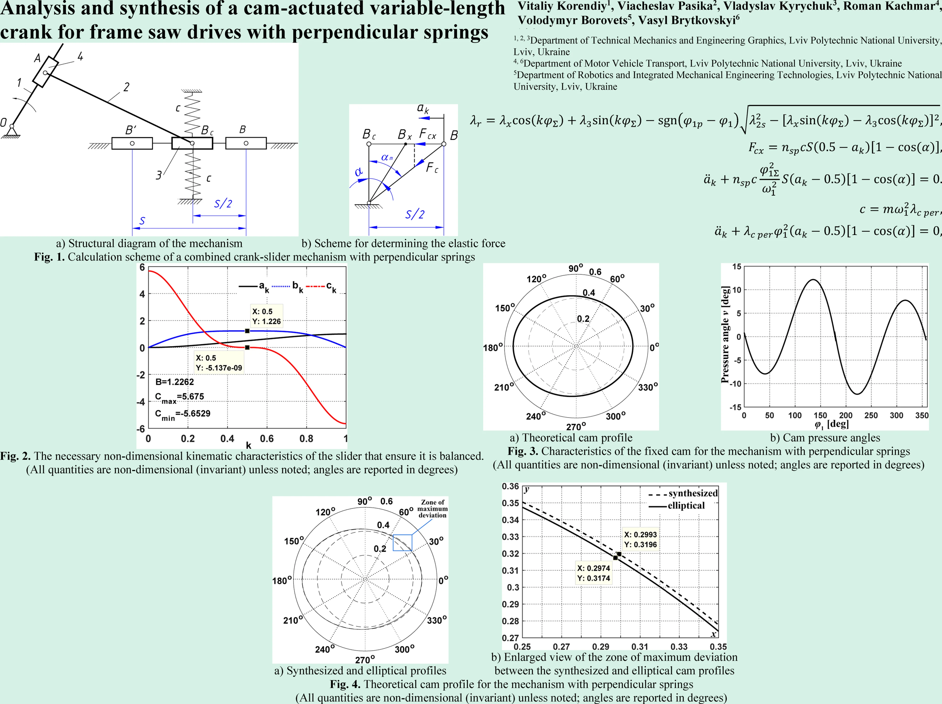
Fig. 1(a) shows the structural diagram of a balancing system for a crank-slider mechanism with springs positioned perpendicular to the direction of slider motion. To reduce the pressure of the slider () on the guide, the springs are mounted on both sides of the slider, forming a pair of springs. The axes of the springs in their undeformed state intersect the slider’s axis of motion at point , which is the midpoint of the stroke S. The objective when considering this structural scheme is the synthesis of such a relative motion between slider 4 and the crank (i.e., the theoretical profile of the fixed cam, not shown in Fig. 1(a), for which the inertia forces of the slider’s unbalanced mass and the elastic forces of the springs, projected onto the direction of the slider’s motion, will balance each other at any slider displacement. To achieve this goal, two tasks must be addressed: first, synthesize a slider law of motion for which the projected elastic forces of the springs and the slider inertia forces will balance each other. In the non-dimensional (invariant) form, the non-dimensional crank length is determined as follows [16]:
where is a new non-dimensional variable; ; is the crank angle range during the slider displacement towards the crank rotation center and at ; is the crank angle range during the displacement away from the rotation center and at ; is the slider stroke; is the length of the connecting rod . All the other non-dimensional parameters of the slider-crank mechanism are thoroughly analyzed in [16].
Fig. 1Calculation scheme of a combined crank-slider mechanism with perpendicular springs
a) Structural diagram of the mechanism
b) Scheme for determining the elastic force
Having obtained the required slider law of motion , let us use Eq. (1) to calculate the required radius vector of the theoretical fixed cam profile . To do this, let us express these forces in terms of the kinematic, inertial, and elastic characteristics of the balancing system.
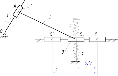
The elastic force of the springs, projected onto the direction of the slider motion, is represented as , where is the elastic force of a stretched spring, and is the angle of inclination of the stretched spring’s axis to the vertical (Fig. 1(b)). From the right-angled triangle let us determine the length of the stretched spring , its deformation , the force , and the angle (where is the number of spring pairs; Fig. 1(a) shows one pair of springs). Substituting these results, we obtain:
where is the spring stiffness.
Let us represent the inertia force as . The derivative of the non-dimensional (invariant) displacement with respect to time is taken using the chain rule for a composite function as . To determine the derivative , let us express in terms of time . It is known that and . Therefore, . From this, let us determine . Similarly, let us determine .
Equating the magnitudes of the inertia forces and the elastic forces yields a differential equation governing the required law of motion for the slider:
To determine the spring stiffness c that ensures slider balancing, we equate the inertia force of the slider and the elastic force of the springs at the extreme position of the mechanism ( 0). Taking into account that in this position the springs are positioned at an angle to the vertical (Fig. 1(b)), we obtain:
where is the non-dimensional (invariant) stiffness parameter for the perpendicular springs.
Taking into account Eq. (4), the differential Eq. (3) takes the form:
for the following initial conditions: , .
The slider experiences two main effects along its stroke: inertia that scales with its instantaneous acceleration and a spring force that acts along the spring axis. Because the springs are placed perpendicular to the stroke, only a component of their force projects along the slider motion. The synthesis selects a periodic slider motion such that, at each position, the projected spring force equals the required inertia force. This “force matching” produces Eq. (5). Once the slider motion is known, the cam-modulated crank length is obtained from Eq. (1), which makes the mechanism generate exactly that motion. The result is a motion with low acceleration in mid-stroke (quasi-constant velocity) and larger acceleration near reversals, so the springs store/release energy where it is most useful while the pressure angle stays within admissible limits.
Thus, the stated goal of the paper has been achieved. A law of motion for the slider (the result of solving differential Eq. (5)) has been synthesized, for which the inertial loads on the slider are eliminated. Based on the synthesized periodic law of motion, the required variable crank length (representing the theoretical profile of the fixed cam) can be determined using the analytical dependency (1).
3. Results and discussion
3.1. Results of numerical simulations
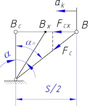
In order to perform further numerical simulation, the following geometrical parameters of a frame saw have been used [16]: slider stroke 0.6 m, length of a connecting rod 2 m, eccentricity 0 m, number of spring pairs , coefficient . Fig. 2 presents the necessary non-dimensional (invariant) kinematic characteristics of the slider for its balancing.
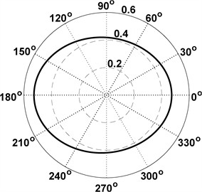
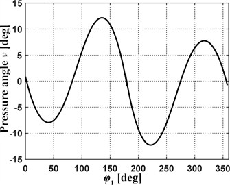
The main difference between the non-dimensional kinematic profiles for the different spring arrangements, particularly, the ones with parallel springs considered in [16] and with perpendicular springs investigated in this paper, is the appearance of the quasi-constant velocity phase in the middle of the kinematic cycle in the case of perpendicular springs (Fig. 2). The kinematic constants are 1.2262 and 5.675 (indicating equal magnitudes for maximum positive and negative values), and the non-dimensional (invariant) kinematic characteristics are symmetrical during the acceleration and deceleration phases.
The synthesized law yields a quasi-constant-velocity segment that covers about 40 % of the slider stroke within ±5 % tolerance (see Fig. 2). In cutting, this reduces velocity ripple through the material, which lowers force variation and can improve surface finish and tool life. Symmetric acceleration and deceleration about mid-stroke limit dynamic skew of the frame and reduce guide wear. Reported kinematic constants indicate equal peak magnitudes in both directions, which aids balance of bearing loads during forward/return strokes.
Fig. 2The necessary non-dimensional kinematic characteristics of the slider that ensure it is balanced. (All quantities are non-dimensional (invariant) unless noted; angles are reported in degrees)
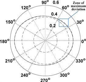
The cam profile and pressure angles for the mechanism with perpendicular springs are shown in Fig. 3. For the synthesized profile, the connecting rod length also increased and is 3.359. The synthesized cam profile resembles an ellipse in shape, whose center is offset from the vertical by 0.0261 to the left. To verify this hypothesis, an ellipse was constructed whose semi-axes are taken as the maximum vertical and horizontal dimensions of the synthesized profile of the cam. They are 0.4996 and 0.4106.
Fig. 3Characteristics of the fixed cam for the mechanism with perpendicular springs (All quantities are non-dimensional (invariant) unless noted; angles are reported in degrees)
a) Theoretical cam profile
b) Cam pressure angles
The maximum pressure angles of the synthesized cam profile (Fig. 3(b)) were found to be approximately 13°, comfortably below typical limits for cam-follower drives (20°...30°) [16]. This reduces normal contact force and local Hertzian stress, easing lubrication demands and follower wear. The pressure-angle distribution is nearly flat through the cutting zone, which helps keep input torque ripple low.
The whole synthesized profile and the considered ellipse are shown in Fig. 4(a). A portion of the synthesized profile and the ellipse, where they differ the most, is shown in Fig. 4(b). The difference between the profiles is insignificant, since the maximum radius vectors differ by no more than 0.00235. Therefore, the synthesized cam profile is well approximated by an ellipse with semi-axes of the lengths of 0.4996 and 0.4106 (non-dimensional), offset slightly from the vertical. The max radial deviation of about 0.00235 implies that standard 2D cam grinding tolerances can reproduce the motion without noticeable degradation of the plateau segment. Using the ellipse surrogate can simplify the numerical control programming and inspection, while the exact profile remains available for high-fidelity builds.
Fig. 4Theoretical cam profile for the mechanism with perpendicular springs (All quantities are non-dimensional (invariant) unless noted; angles are reported in degrees)
a) Synthesized and elliptical profiles
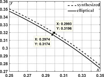
b) Enlarged view of the zone of maximum deviation between the synthesized and elliptical cam profiles
4. Discussion of the results obtained
The carried-out investigations addressed the persistent challenge of high unbalanced inertia forces in conventional frame saws, which limits their operating speed, degrades cut quality, and necessitates heavy, robust construction. Traditional crank-slider mechanisms inherently generate significant dynamic loads proportional to the square of the operating speed, making substantial increases in productivity difficult without compromising reliability or requiring excessively massive designs. The primary working hypothesis of this research was that by synthesizing the main drive mechanism based on a prescribed periodic law of motion for the slider, specifically designed to counteract inertial effects, it would be possible to achieve effective dynamic balancing. This approach departs from conventional mass balancing techniques or simple passive compensation methods by integrating balancing directly into the kinematic design of the drive. The methodology employed a novel crank-slider mechanism with a programmatically variable crank length, controlled via a fixed cam profile (Fig. 4), allowing for the generation of non-standard slider motion profiles tailored for force cancellation.
A significant finding is the difference in the synthesized motion laws required for balancing with parallel springs [16] versus perpendicular springs (Fig. 2). The parallel spring configuration, due to its linear force-displacement characteristic, necessitates a simple cosine motion law for the slider to achieve balance [16]. In contrast, the non-linear geometry and force projection associated with the perpendicular springs require a more complex motion profile, synthesized by solving differential Eq. (5). This more complex profile notably features a quasi-constant velocity phase spanning over 40 % of the stroke within a 5 % tolerance (Fig. 2). This extended period of near-constant velocity could have positive implications for the sawing process itself, potentially leading to more uniform cutting forces, improved surface finish, and reduced tool wear, aspects often influenced by cutting speed variations [6, 7]. The synthesized motion profiles exhibit symmetry between the acceleration and deceleration phases, which contributes to the periodic nature required for continuous operation.
The practical implications of the results obtained for the operation of the wood- and stone-cutting frame saws are as follows. The 40 % mid-stroke quasi-constant-velocity segment reduces velocity ripple across the cut and can lower tool-force variation and wear. Maximum pressure angle of about 13° supports low follower loads and easier lubrication. The ellipse approximation with small radial deviation simplifies numerical control programming and inspection while preserving kinematics. The stiffness selection rule and perpendicular-spring layout reduce reversal transients and bearing loads at higher stroke rates.
Owing to the strict length limit of this paper, we reported the synthesis method and comparative simulations only. Full experimental characterization is outside the present scope. In ongoing work, we are preparing a benchtop cam-slider rig with a 3D-printed quasi-elliptic cam, an encoder-instrumented motor drive, linear guides, and a laser displacement sensor. The validation will compare measured and simulated slider velocity versus cam angle and will report root-mean-square error and the fraction of the ±5 % quasi-constant-velocity plateau; a pressure-angle proxy will be derived from motor torque/current. Robustness to ±10 % variations in spring stiffness and slider mass and a manufacturability tolerance sweep of ±0.2 mm cam radius will also be assessed. Results will be presented in an extended publication.
5. Conclusions
A synthesis framework was established for a crank-slider mechanism with perpendicular springs in which the slider’s periodic motion is designed to balance inertia and elastic forces; the governing second-order equation defines the motion law, and the variable crank length (theoretical cam profile) follows directly from it. A closed-form stiffness selection for the spring set was obtained via a non-dimensional stiffness parameter specific to the perpendicular layout, providing a practical design rule for balancing at the stroke extremes. For a typical frame-saw geometry, simulations predict a broad quasi-constant-velocity phase over 40 % of the stroke (±5 %), with symmetric acceleration-deceleration – conditions favorable to uniform cutting. The synthesized cam is accurately represented by an ellipse (maximum radial error of about 0.00235), and its pressure angles are approximately 13°, well below customary admissible values – supporting manufacturability and smooth transmission. The required connecting-rod length increases in the balanced solution (non-dimensional value 3.359), a factor to be considered in packaging the mechanism within existing frames.
Overall, a cam-modulated variable-length crank combined with perpendicular springs provides a viable route to reduce unbalanced loads, temper reversal transients, and shape the reciprocation law without auxiliary counter-masses. Future work should incorporate friction and guide compliance, assess multi-pair spring configurations, and validate the predicted benefits experimentally on a full-scale frame saw.
References
-
O. Kachur and V. Korendiy, “Dynamic behavior of vibratory screening conveyor equipped with crank-type exciter,” in Lecture Notes in Mechanical Engineering, Cham: Springer Nature Switzerland, 2023, pp. 44–53, https://doi.org/10.1007/978-3-031-32774-2_5
-
V. Korendiy, V. Gursky, O. Kachur, V. Gurey, O. Havrylchenko, and O. Kotsiumbas, “Mathematical modeling of forced oscillations of semidefinite vibro-impact system sliding along rough horizontal surface,” Vibroengineering Procedia, Vol. 39, pp. 164–169, Dec. 2021, https://doi.org/10.21595/vp.2021.22298
-
V. Korendiy, O. Lanets, O. Kachur, P. Dmyterko, and R. Kachmar, “Determination of inertia-stiffness parameters and motion modelling of three-mass vibratory system with crank excitation mechanism,” Vibroengineering Procedia, Vol. 36, pp. 7–12, Mar. 2021, https://doi.org/10.21595/vp.2021.21924
-
V. Pasika, P. Nosko, O. Nosko, O. Bashta, V. Heletiy, and V. Melnyk, “A method to synthesise groove cam Geneva mechanisms with increased dwell period,” Proceedings of the Institution of Mechanical Engineers, Part C: Journal of Mechanical Engineering Science, Vol. 238, No. 15, pp. 7544–7555, Feb. 2024, https://doi.org/10.1177/09544062241234477
-
D. Sun and J. Zhang, “Dynamics modeling and analysis of feed drive system for a frame saw machine considering time-varying load,” Mechanics and Industry, Vol. 22, p. 26, Apr. 2021, https://doi.org/10.1051/meca/2021019
-
P. Dong, J. Zhang, C. Ouyang, D. Sun, and J. Wu, “Investigation on sawing performance of diamond frame saw based on reciprocating swing in processing hard stone,” Journal of Materials Processing Technology, Vol. 295, p. 117171, Sep. 2021, https://doi.org/10.1016/j.jmatprotec.2021.117171
-
K. A. Orlowski, D. Chuchala, M. Szczepanski, W. Migda, W. Wojnicz, and J. Sandak, “Lateral forces determine dimensional accuracy of the narrow-kerf sawing of wood,” Scientific Reports, Vol. 12, p. 86, Jan. 2022, https://doi.org/10.1038/s41598-021-04129-3
-
J. Pozo-Palacios, N. J. Fulbright, J. A. F. Voth, and J. D. van de Ven, “Comparison of forward and inverse cam generation methods for the design of cam-linkage mechanisms,” Mechanism and Machine Theory, Vol. 190, p. 105465, Dec. 2023, https://doi.org/10.1016/j.mechmachtheory.2023.105465
-
A. Tuleshov, R. Halicioglu, A. Shadymanova, and M. Kuatova, “Kinematic synthesis method and eccentricity effects of a Stephenson mechanism,” Mechanical Sciences, Vol. 12, No. 1, pp. 1063–1073, Jan. 2021, https://doi.org/10.5194/ms-12-1-2021
-
K. Wittek, F. Geiger, and M. G. Justino Vaz, “Characterization of the system behaviour of a variable compression ratio (VCR) connecting rod with eccentrically piston pin suspension and hydraulic moment support,” Energy Conversion and Management, Vol. 213, p. 112814, Jun. 2020, https://doi.org/10.1016/j.enconman.2020.112814
-
Y. Yu, S. Wei, Q. Ji, and Z. Yang, “Design, dynamics analysis, and real-time stiffness control of a variable stiffness joint,” Electronics, Vol. 9, No. 6, p. 973, Jun. 2020, https://doi.org/10.3390/electronics9060973
-
W. Fiebig and W. Prastiyo, “Utilization of mechanical resonance for the enhancement of slider-crank mechanism dynamics in gas compression processes,” Energies, Vol. 15, No. 20, p. 7769, Oct. 2022, https://doi.org/10.3390/en15207769
-
R.-B. Hao, Z.-Q. Lu, H. Ding, and L.-Q. Chen, “Orthogonal six-DOFs vibration isolation with tunable high-static-low-dynamic stiffness: Experiment and analysis,” International Journal of Mechanical Sciences, Vol. 222, p. 107237, May 2022, https://doi.org/10.1016/j.ijmecsci.2022.107237
-
Z. Ma, R. Zhou, and Q. Yang, “Recent advances in quasi-zero stiffness vibration isolation systems: an overview and future possibilities,” Machines, Vol. 10, No. 9, p. 813, Sep. 2022, https://doi.org/10.3390/machines10090813
-
Y. Zhang, T. Zheng, Z. Zhou, and W. Fu, “Design and control of an active-passive integrated six-dimensional orthogonal vibration isolation platform,” Applied Sciences, Vol. 15, No. 7, p. 3437, Mar. 2025, https://doi.org/10.3390/app15073437
-
V. Korendiy, V. Pasika, V. Kyrychuk, B. Vasyliv, P. Hashchuk, and I. Zakhara, “Analysis and synthesis of a controllable crank-slider mechanism with parallel springs for frame saws,” Vibroengineering Procedia, Vol. 59, pp. 41–49, Sep. 2025, https://doi.org/10.21595/vp.2025.25178
About this article

The authors have not disclosed any funding.
The datasets generated during and/or analyzed during the current study are available from the corresponding author on reasonable request.
The authors declare that they have no conflict of interest.
