Abstract
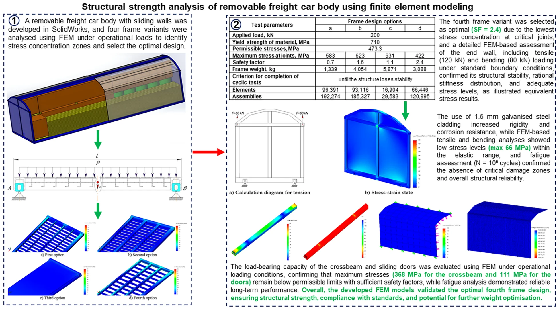
The paper analyses foreign removable body designs whose technical solutions were adopted in the modelling of the load-bearing elements of a freight car removable body. Virtual models were developed and analysed in SolidWorks Simulation using the finite element method. The simulations enabled identification of stress concentration zones, safety factors, and fatigue resistance indicators under operational loads while considering detailed kinematic boundary conditions and realistic fastening parameters (hinged or rigid). Particular attention was given to the frame as the primary load-bearing element; static analysis showed a maximum von Mises stress of 471 MPa at a permissible value of 473.3 MPa, corresponding to a safety factor of 1.5, while the end walls, crossbeam and sliding doors met applicable technical and regulatory requirements. The results confirm the reliability of the proposed design and provide a basis for further optimisation of metal consumption without compromising strength compliance.
1. Introduction
Improving the efficiency of freight transportation and increasing the throughput and carrying capacity of heavily loaded railway sections under rolling stock shortages requires infrastructure modernisation, integration of international railway networks, and the introduction of innovative rolling stock with improved technical and economic characteristics [1, 2]. Wagons with removable and interchangeable bodies are particularly promising because they reduce downtime during seasonal fluctuations by minimising loading and unloading time and labour when changing cargo types. Recent international studies confirm the effectiveness of this approach: European researchers focus on modular freight wagon concepts, American studies emphasise lightweight aluminium and composite structures, and Chinese works investigate sensor-based monitoring and AI-assisted weight optimisation of freight bodies [3-6]. This study investigates the strength characteristics of the load-bearing elements of a freight car removable body using the finite element method implemented in SolidWorks Simulation [7]. The methodology includes 3D modelling, material definition, boundary conditions [8], load application, and stress-strain evaluation based on the von Mises criterion to identify critical zones, verify strength, and optimise structural parameters in accordance with regulatory requirements.
2. Methodology and results
Based on a review of existing removable and replaceable body designs, taking into account their advantages and disadvantages [9, 10], it was decided to develop a new design for a removable body (Fig. 1) with sliding side walls and a roof, allowing the transport of various packaged and palletised cargoes requiring protection from atmospheric precipitation, with their fastening in accordance with technical requirements and standards.
Fig. 1Virtual model of the removable body loaded with packaged and palletised cargo
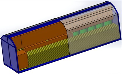
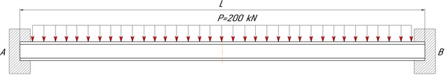
The removable body was designed and analysed using parametric modelling in SolidWorks. The structure consists of a frame, two end walls, a crossbeam, and four sliding roof-integrated side doors [11]. The load-bearing elements are fabricated from high-strength steel profiles [12, 13] by semi-automatic welding. The end walls consist of box-section beams with arched upper members and are equipped with eight fittings for securing and lifting operations, while the side walls are designed as independent sliding doors with roller suspensions and locking devices. The selection of the main load-bearing elements [14, 15] was based on a comparative analysis of four frame variants with identical dimensions (12,200×3,200×180 mm). Strength analysis was carried out under operational loads (Fig. 2) and kinematic boundary conditions, with hinged supports and uniformly distributed vertical loading accounting for the self-weight of the structure.
Fig. 2Kinematic boundary conditions and loading scheme of the removable body frame
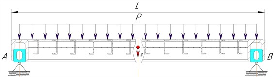
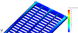
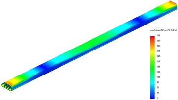
Fig. 3Critical stress concentration zones in the analysed removable body frame variants
a) First option
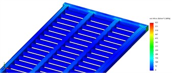
b) Second option

c) Third option
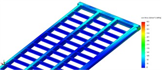
d) Fourth option
Strength analysis of the removable body frames (Fig. 3) made it possible to identify the most highly stressed areas and structural nodes of the analysed variants, requiring reinforcement or design modification [16]. The maximum stresses were concentrated in the joints between the longitudinal and transverse end beams.
Stress-strain analysis showed that maximum equivalent stresses [17] are concentrated in the welded joints of the main longitudinal and transverse beams. To improve load-bearing capacity, high-strength AISI 4340 steel was selected for the principal beams, while intermediate members were designed from standard rectangular tubular profiles, enabling local strengthening with reduced overall metal consumption. However, the use of AISI 4340 is limited by reduced weldability and strict technological requirements, including preheating to 250-300 °C, controlled welding with chromium-molybdenum filler, and post-weld heat treatment (550-650 °C) to relieve stresses [18, 19]. The comparative strength results of the proposed frame variants, reflecting differences in load paths, joint stiffness and material distribution, are presented in Table 1.
Table 1Results of strength calculations for removable body frames
Test parameters | Frame design options | |||
a | b | c | d | |
Applied load, kN | 200 | |||
Yield strength of material, MPa | 710 | |||
Permissible stresses, MPa | 473.3 | |||
Maximum stress at joints, MPa | 583 | 623 | 631 | 422 |
Safety factor | 0.7 | 1.6 | 1.1 | 2.4 |
Frame weight, kg | 1,339 | 4,054 | 5,871 | 3,088 |
Criterion for completion of cyclic tests | until the structure loses stability | |||
Elements | 96,391 | 93,116 | 16,904 | 66,446 |
Assemblies | 192,274 | 185,327 | 29,583 | 120,995 |
Analysis of Table 1 confirmed the optimality of the fourth frame variant, which exhibited the lowest stress concentration at critical joints and the highest safety factor (2.4), and was therefore adopted as the basic design. A comprehensive FEM-based assessment, including static and cyclic analyses, was performed to evaluate the fatigue resistance of the end wall frame. The square-section beams and arched upper ties provide a rational stiffness distribution under tension and bending, which is consistent with published studies on framed freight structures [20]. Under the adopted standard-based boundary conditions (Fig. 4(a)), the end wall was supported on hinged fittings, and tensile forces of 120 kN were applied to the upper fittings with load coefficients in accordance with standards [14, 15]. Additional bending analysis using horizontal loads of 80 kN simulated inertial effects, enabling evaluation of structural stability and prevention of residual deformations in critical joints. The equivalent von Mises stresses are shown in Fig. 4(b).
Fig. 4Boundary conditions and equivalent stress distribution in the removable body end wall
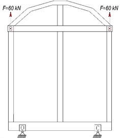
a) Calculation diagram for tension
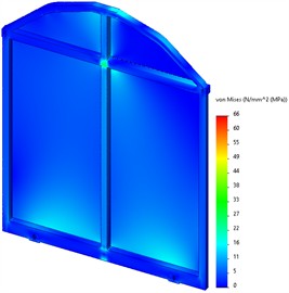
b) Stress-strain state
Galvanised steel sheet (1.5 mm) was used for end wall cladding, increasing rigidity and corrosion resistance. Analytical tensile and bending simulations showed a maximum equivalent stress of 66 MPa in the upper frame near the crossbeam attachment, which is within the elastic range and well below the yield strength, ensuring a sufficient safety margin [21]. Fatigue analysis at 106 cycles revealed no critical damage zones, confirming structural reliability.
The load-bearing capacity of the AISI 4340 steel crossbeam was also evaluated. FEM analysis under kinematic boundary conditions (Fig. 5) with a uniformly distributed load of 200 kN simulated compressive forces during lifting, enabling assessment of bending stiffness and operational reliability.
Fig. 5Kinematic boundary conditions of the crossbeam during strength calculation
The calculations produced equivalent von Mises stress distributions (Fig. 6(a)) and the static safety factor of the crossbeam structure (Fig. 6(b)).
Fig. 6Equivalent stress distribution and safety factor of the crossbeam
a) Equivalent stresses
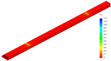
b) Safety factor
Strength analysis of the crossbeam showed a maximum equivalent stress of 368 MPa at a permissible value of 473.3 MPa, corresponding to a safety factor of 1.9 and full compliance with regulatory requirements. FEM analysis was also performed for the sliding side doors designed to enable loading and unloading through the upper opening. Each door is hinged to the body frame at the lower part and fixed to the crossbeam at the upper part. To reduce weight while maintaining strength, the doors were manufactured from 6063 aluminium alloy with hollow profiles and 1.5 mm corrugated sheet cladding [22, 23]. Strength and durability were evaluated under distributed outward forces of 10 kN simulating inertial loads during uneven train motion. The simulation identified stress concentration zones at joints and attachment points and assessed structural rigidity under bending. The results are presented in Fig. 7.
Fig. 7Equivalent stress state and fatigue strength of the removable body sliding doors
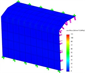
a) Stress-strain state
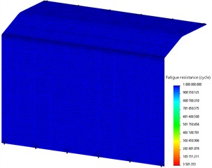
b) Fatigue strength
The strength analysis of the sliding door structural elements showed that the highest equivalent stresses occur at the roller support attachment points, reaching 111 MPa, which agrees with the typical localisation of peak stresses in movable aluminium-framed panels and remains below the permissible limit of 140 MPa. Fatigue strength analysis also demonstrated that the fatigue safety factor significantly exceeds unity, confirming reliable and trouble-free operation of the sliding doors throughout the entire service life of the removable body.
3. Conclusions
Strength investigations of the load-bearing elements of the removable body were performed using the finite element method in the SolidWorks environment. Finite element models of the main structural components were developed to evaluate their strength characteristics and construct equivalent von Mises stress distribution diagrams. Comparative strength analysis of four frame variants showed that the fourth design provides the most favourable stress distribution and safety factor. Analysis of the stress distribution in the body frame, end walls, crossbeam and sliding doors under operational static and dynamic loading conditions confirmed that the maximum equivalent stresses do not exceed the permissible values of the selected materials. The developed numerical models proved to be adequate, and the obtained results demonstrate high operational reliability of the structure while ensuring optimised metal consumption and efficient performance under static and dynamic loading conditions.
For the selected fourth frame variant, the maximum equivalent stress reached 422 MPa at a permissible value of 473.3 MPa, with a safety factor of 2.4, which justifies its adoption as the base design. For the crossbeam under a design load of 200 kN, the maximum equivalent stress was 368 MPa with a safety factor of 1.9. In the end wall frame, peak stresses did not exceed 66 MPa and were localised near the crossbeam connection, confirming a high static strength margin. For the sliding doors, the maximum equivalent stress reached 111 MPa at the roller support attachment points, with a permissible value of 140 MPa, while fatigue analysis confirmed reliable operation of the structural elements throughout the service life. The obtained results can be used for further local weight optimisation of the structural geometry, reduction of metal consumption, preparation of design documentation, and future experimental validation of the proposed design.
References
-
S. V. Ustiantsev and N. V. Pershkhalo, Era Lorenzo: Experience of Successful Adaptation of Foreign Designs and Technologies in Transport Engineering. (in Russian), Nizhny Tagil, Russia: UVZ, 2012.
-
Y. P. Boronenko, R. V. Rahimov, A. A. Komaidanov, and D. S. Zafarov, “Impact of freight car characteristics and operating conditions on the energy performance index of rolling stock,” in Proceedings of the 11th International Conference on Industrial Engineering, pp. 439–448, Sep. 2025, https://doi.org/10.1007/978-3-032-04273-6_41
-
O. Fomin, M. Gorbunov, A. Lovska, J. Gerlici, and K. Kravchenko, “Dynamics and strength of circular tube open wagons with aluminum foam filled center sills,” Materials, Vol. 14, No. 8, p. 1915, Apr. 2021, https://doi.org/10.3390/ma14081915
-
J. Pan, Z. Chen, and Z. Hong, “A novel method to estimate the fracture toughness of pressure vessel ferritic steels in the ductile to brittle transition region using finite element analysis and Master Curve method,” International Journal of Pressure Vessels and Piping, Vol. 176, p. 103949, Sep. 2019, https://doi.org/10.1016/j.ijpvp.2019.103949
-
A. Cascino, E. Meli, and A. Rindi, “Dynamic size optimization approach to support railway carbody lightweight design process,” Proceedings of the Institution of Mechanical Engineers, Part F: Journal of Rail and Rapid Transit, Vol. 237, No. 7, pp. 871–881, Nov. 2022, https://doi.org/10.1177/09544097221140933
-
W. G. Lee, J.-S. Kim, S.-J. Sun, and J.-Y. Lim, “The next generation material for lightweight railway car body structures: Magnesium alloys,” Proceedings of the Institution of Mechanical Engineers, Part F: Journal of Rail and Rapid Transit, Vol. 232, No. 1, pp. 25–42, Apr. 2016, https://doi.org/10.1177/0954409716646140
-
J. Gerlici, A. Lovska, and M. Pavliuchenkov, “Study of the dynamics and strength of the detachable module for long cargoes under asymmetric loading diagrams,” Applied Sciences, Vol. 14, No. 8, p. 3211, Apr. 2024, https://doi.org/10.3390/app14083211
-
J. Dižo, J. Harušinec, and M. Blatnický, “Computation of modal properties of two types of freight wagon bogie frames using the finite element method,” Manufacturing Technology, Vol. 18, No. 2, pp. 208–214, Apr. 2018, https://doi.org/10.21062/ujep/79.2018/a/1213-2489/mt/18/2/208
-
J. Liu, G. Feng, J. Wang, H. Ren, W. Song, and P. Lin, “Fatigue life assessment in the typical structure of large container vessels based on fracture mechanics,” Journal of Marine Science and Engineering, Vol. 11, No. 11, p. 2075, Oct. 2023, https://doi.org/10.3390/jmse11112075
-
J. Gerlici, A. Lovska, G. Vatulia, M. Pavliuchenkov, O. Kravchenko, and S. Solčanský, “Situational adaptation of the open wagon body to container transportation,” Applied Sciences, Vol. 13, No. 15, p. 8605, Jul. 2023, https://doi.org/10.3390/app13158605
-
A. Lovska, I. Stanovska, Y. Pelypenko, H. Barsukova, and O. Yurchenko, “Determining the strength of a frame in a railroad open wagon with slings in its structure to improve its operational energy efficiency,” Eastern-European Journal of Enterprise Technologies, Vol. 5, No. 7 (137), pp. 40–47, Oct. 2025, https://doi.org/10.15587/1729-4061.2025.340014
-
Z. Wang, C. Qian, and Z. Wu, “Stress analysis and structural improvement of LNG tank container frames under impact from railway transport vehicles,” Applied Sciences, Vol. 13, No. 24, p. 13335, Dec. 2023, https://doi.org/10.3390/app132413335
-
M. Mičian, M. Frátrik, and D. Kajánek, “Influence of welding parameters and filler material on the mechanical properties of HSLA steel S960MC welded joints,” Metals, Vol. 11, No. 2, p. 305, Feb. 2021, https://doi.org/10.3390/met11020305
-
“GOST R ISO 3874-2008, Series 1 freight containers – overloading and securing,” (in Russian), Standardinform, Moscow, Russia, 2008.
-
“GOST R 51876-2008, Series 1 freight containers – technical requirements and testing methods,” (in Russian), Standardinform, Moscow, Russia, 2011.
-
R. Rahimov and D. Zafarov, “Justification of the possibility for extending the service life of cast parts of a three-axle bogie based on results of the running strength tests to determine their loading,” Communications – Scientific letters of the University of Zilina, Vol. 27, No. 3, pp. B170–B185, Jul. 2025, https://doi.org/10.26552/com.c.2025.035
-
T. T. Song, “Research on Q450NQR1 high-strength sheet metal forming springback and application of shallow drawing,” Shandong University, Jinan, China, 2011.
-
W. Yue and X. Chen, “Three-dimensional liquid sloshing numerical analysis on a new designed tank container,” in ASME 2019 Pressure Vessels and Piping Conference, p. V005T09A008, Jul. 2019, https://doi.org/10.1115/pvp2019-93455
-
J. Cao, M. Han, and J. Y. Qi, “The study on medium filling scheme of LNG tank container impact testing based on ANSYS,” Advanced Materials Research, Vol. 912-914, pp. 869–872, Apr. 2014, https://doi.org/10.4028/www.scientific.net/amr.912-914.869
-
S. Tiernan and M. Fahy, “Dynamic FEA modelling of ISO tank containers,” Journal of Materials Processing Technology, Vol. 124, No. 1-2, pp. 126–132, Jun. 2002, https://doi.org/10.1016/s0924-0136(02)00196-6
-
M. Opala, J. Korzeb, S. Koziak, and R. Melnik, “Evaluation of stress and fatigue of a rail vehicle suspension component,” Energies, Vol. 14, No. 12, p. 3410, Jun. 2021, https://doi.org/10.3390/en14123410
-
F. Klimenda and J. Soukup, “Modal analysis of thin aluminium plate,” Procedia Engineering, Vol. 177, pp. 11–16, Jan. 2017, https://doi.org/10.1016/j.proeng.2017.02.176
-
F. Wang et al., “Superb mechanical properties of a novel high-Zn Al alloy processed via two-step thermomechanical treatments,” Materials Letters, Vol. 369, p. 136747, Aug. 2024, https://doi.org/10.1016/j.matlet.2024.136747
About this article

The authors have not disclosed any funding.
The datasets generated during and/or analyzed during the current study are available from the corresponding author on reasonable request.
The authors declare that they have no conflict of interest.
