Abstract
Construction near existing structures can induce ground movements that compromise foundation performance, including excessive settlements and loss of bearing capacity. This study evaluates reinforcement strategies for deteriorated shallow footings and pile foundations under combined vertical and lateral loads. Reinforcement is achieved by transferring loads to deeper, more stable soil strata. A finite element analysis simulated soil-structure interaction and assessed total and differential displacements. Cylindrical Type Sheet Piles (CTSP) were installed at varying depths and inclinations, and compared with Deep Cement Mixing (DCM). For footing foundations, CTSP installation reduced horizontal displacement by 72-80% and vertical settlement by 96-98 %. Additional reinforcement using H-beams and inclined CTSP slightly varied reduction, with horizontal displacement decreasing 22-72 % and vertical settlement 23-96 %. For pile foundations, CTSP reduced horizontal displacement by 93-95 % and vertical settlement by 97 %, while DCM provided an economical alternative with 81 % and 86 % reduction, respectively. Increasing CTSP embedment depth from 10 m to 20 m further minimized displacement, particularly in pile foundations. These results provide quantitative guidance for selecting optimal reinforcement systems to enhance stability and performance of existing foundations under complex geotechnical conditions.
1. Introduction
In the design of foundations in the vicinity of existing structures, the impact of new construction and the performance of excavation support systems on the existing foundation must be considered. If the evaluation indicates that the existing foundation elements will undergo unacceptable deformations or reductions in support capacity, then reinforcement of the existing foundations may be required. In addition, reinforcement is needed to improve earthquake resistance and to prevent reduction of bearing capacity caused by riverbed erosion.
Strengthening worn foundations involves upgrading the existing foundation system by extending it into deeper, more stable soil layers beneath the surface. This approach provides additional vertical load-bearing capacity not anticipated in the original design [1].
Reduction of foundation bearing capacity due to the construction and long-term presence of excavation support systems can occur for any existing foundation that falls within the influence zone. A decrease in bearing capacity is often associated with foundation settlement in relation to the surrounding ground surface. Evaluation of the impact of ground movements on adjacent structures should consider both total and differential vertical and lateral movements. The most significant effects on adjacent structures are likely to result from distortion of the structures, both due to differential settlements and differential lateral movements. Differential ground settlements directly affect footings and may also create down-drag loads on deep foundations. Reinforcement of existing foundations should be considered when estimated ground movements exceed tolerable limits for existing structures [2-5].
In this study, Cylinder Type Sheet Pile (CTSP) was used for reinforcement of existing outworn foundation and, in some cases, was combined with Deep Cement Mixing (DCM). The types of existing deteriorated foundations considered in this study are footing and pile foundations.
The novelty of this study lies in the combined application of CTSP and DCM for the reinforcement of existing deteriorated foundations under various loading conditions, as well as in the comparative evaluation of their effectiveness for both footing and pile foundations. In addition, the influence of CTSP embedment depth and inclination on displacement reduction is systematically investigated.
2. Geometry of proposed foundations and material properties
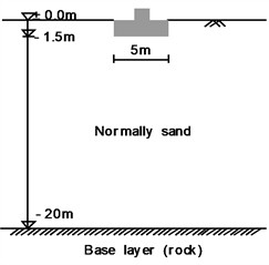
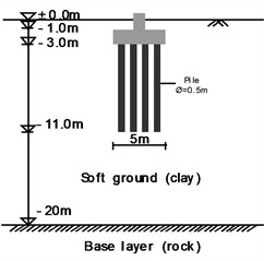
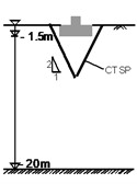
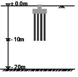
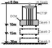
In this study, two types of existing outworn foundations were considered, namely footing and pile foundations. The axial load of each foundation is derived from dead and live load of the super structure (e.g., a bridge), while horizontal loads are included by earthquake actions, deep excavation effect, riverbed erosion, etc. For the footing foundation, an axial load of 600 kN and a horizontal load of 60 kN were applied. For the pile foundation, an axial load of 1000 kN and a horizontal load of 100 kN were applied. The geometrical model consists of a footing with a width of 5.0 m resting on a normally consolidated sand deposit with a depth of 20 m, and pile foundation with a 5.0 m wide pile cap resting on a soft clay deposit with a depth of 20 m, as shown in Fig. 1.
Fig. 1Geometrical model of foundations: a) footing, b) pile
a)
b)
To represent the geotechnical properties of subsoil, standard material properties collected by references were used. The soil behavior was modeled using the Mohr-Coulomb model, while concrete behavior was assumed to be linear elastic. The properties of the material used for the numerical analysis are given in Table 1 and 2. For CTSP (cylinder type sheet pile), the material properties were taken from published studies [6]. The numerical analysis was performed using a finite element approach to evaluate displacement behavior under different reinforcement configurations. The boundary conditions of the structural model were defined assuming a fixed base at the foundation level. Soil-structure interaction was not explicitly modeled; instead, the foundation was considered rigid, which is a common assumption for preliminary dynamic analysis. Damping effects were not measured experimentally and were therefore assumed based on commonly adopted values in structural dynamics. A classical viscous damping model with a constant damping ratio of 5 % was used, which is widely accepted for preliminary analysis of civil engineering structure
Table 1Material properties of soil and interface materials
Material | Constitutive model | Drainage condition | (N/m3) | (N/m3) | (N/m2) | Poisson’s ratio, | Phi |
DCM | Linear elastic | D | 16500 | 19500 | – | 0.35 | – |
Concrete | Linear elastic | D | 24000 | 24000 | – | 0.35 | – |
Sand | Mohr-Coulomb | D | 16000 | 20000 | 1000 | 0.3 | 30 |
Clay | Mohr-Coulomb | UnD | 15000 | 18000 | 2000 | 0.33 | 24 |
Rock | Mohr-Coulomb | D | 27000 | 27000 | 2700000 | 0.3 | 30 |
Note: D – drained; UnD – undrained; – unit weight in unsaturated condition; – unit weight in saturated condition | |||||||
Table 2Mechanical characteristics of reinforcement elements
Reinforcing element | Material behavior | Axial stiffness, EA (N/m) | Bending stiffness, EI (Nm2/m) | Poisson’s ratio, |
Pile Toe | Elastic | 2×10⁹ | 8×10⁶ | 0.20 |
Pile | Elastic | 2×10⁹ | – | – |
Strut | Elastic | 2×10⁹ | – | – |
H-beam | Elastic | 4.374×10⁹ | 1.332×10⁸ | 0.32 |
CTSP | Elastic | 5×10⁹ | 1.4×10¹² | 0.32 |
3. Types of reinforcement for outworn foundations
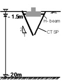
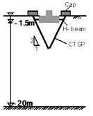
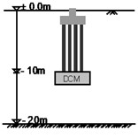
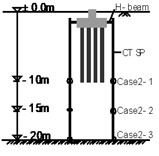
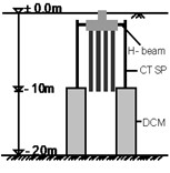
Reinforcement of existing outworn foundation was considered under two types of foundation in soil with several cases. The effect of fixing the CTSP at ground level was also examined. The configurations of reinforcement systems are schematically shown in Figs. 2 and 3. For the footing foundation (Cases 1 and 2) and pile foundation (Cases 2 and 4), CTSP was installed into the ground with different embedment depths (5 m, 10 m, 15 m, and 20 m).
Fig. 2Configuration of reinforcement types for footing foundation
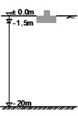
a) Initial
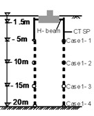
b) Case 1
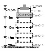
c) Case 2
d) Case 3
e) Case 4
f) Case 5
Fig. 3Configuration of reinforcement types for pile foundation
a) Initial
b) Case 1
c) Case 2
d) Case 3
e) Case 4
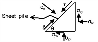
For footing foundations, previous studies have shown that increasing the inclination of micro-piles leads to an increase in bearing capacity [7]. Based on this concept, the present study investigates a sheet pile installed at a 60° inclination. The interaction between the sheet pile and the surrounding soil generates normal and shear stresses along the sheet pile-soil interface [8]. A free-body diagram illustrating the distribution of these normal and shear stresses when the sheet pile is embedded at an angle relative to the horizontal ground surface is presented in Fig. 4. The corresponding expressions for the normal and shear stresses acting on the sheet pile are provided by the following equations:
The resisting force, , developed along the sheet pile is given by:
where, is the friction angle between the sheet pile and the soil. The vertical component of the resisting force () contributes to resisting vertical loads, thereby improving bearing capacity and reducing settlement.
Fig. 4A free-body diagram as a result of sheet pile-soil interaction
4. Deformation behavior of foundations
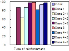
In this paper, a comparative study of different types of reinforcement systems for each foundation type was carried out. The simulation results for horizontal and vertical displacements are summarized in Tables 3 and 4. Figs. 5 and 6 show the percentage reduction in displacement for various reinforcement types of footing and pile foundations, while Fig. 7 shows the displacement with variation of CTSP embedment depth in footing foundations (Cases 2 and 3) and pile foundations (Cases 2 and 4).
Table 3Displacements of footing foundations under various reinforcement configurations
Case | Reinforcement configuration | Horizontal displacement (mm) | Reduction in horizontal displacement (%) | Vertical displacement (mm) | Reduction in vertical displacement (%) |
Initial | No reinforcement | 60 | 0 | 319 | 0 |
1-1 | CTSP | 60.3 | –0.42 | 206 | 35.26 |
1-2 | CTSP | 37.3 | 37.80 | 122 | 61.77 |
1-3 | CTSP | 25 | 58.34 | 79 | 75.23 |
1-4 | CTSP | 11.8 | 80.39 | 8.99 | 97.18 |
2-1 | CTSP+DCM | 44.3 | 26.15 | 139 | 56.26 |
2-2 | CTSP+DCM | 29.5 | 50.84 | 91.8 | 71.22 |
2-3 | CTSP+DCM | 19.6 | 67.37 | 53.8 | 83.12 |
2-4 | CTSP+DCM | 12.4 | 79.34 | 4.57 | 98.57 |
3 | CTSP(60°) | 46.3 | 22.81 | 245 | 23.25 |
4 | CTSP(60°)+H-beam | 32.1 | 46.61 | 144 | 54.80 |
5 | CTSP(60°)+H-beam+Strut | 16.8 | 72.08 | 11.3 | 96.46 |
The percentage reduction in displacement is calculated using the following expression:
where: – percentage decrease of displacement; – displacement in the initial condition; – displacement with reinforcement.
Table 4Pile foundation displacements for different reinforcement configurations (mm)
Case | Reinforcement configuration | Horizontal displacement (mm) | Reduction in horizontal displacement (%) | Vertical displacement (mm) | Reduction in vertical displacement (%) |
Initial | No reinforcement | 639 | 0 | 1340 | 0 |
1 | DCM | 121 | 81.13 | 185 | 86.16 |
2-1 | CTSP | 277 | 56.67 | 501 | 62.64 |
2-2 | CTSP | 105 | 83.62 | 175 | 86.93 |
2-3 | CTSP | 29.7 | 95.35 | 38.5 | 97.13 |
3 | CTSP+DCM | 40.4 | 93.67 | 27.2 | 97.97 |
4-1 | CTSP+DCM | 138 | 78.40 | 249 | 81.42 |
4-2 | CTSP+DCM | 94.1 | 85.26 | 93.4 | 93.03 |
4-3 | CTSP+DCM | 38.2 | 94.86 | 33.9 | 97.47 |
Fig. 5Comparison of deformation for various reinforcement types of footing foundation
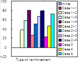
a) Horizontal displacement
b) Vertical displacement
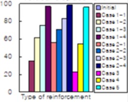
Fig. 6Comparison of deformation for various reinforcement types of footing foundation
a) Vertical displacement
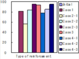
b) Horizontal displacement
Fig. 7Variation of deformation for various reinforcement types of footing and pile foundation
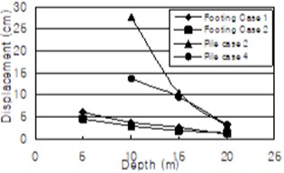
a) Depth vs horizontal displacement
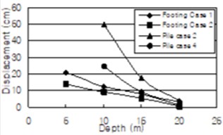
b) Depth vs vertical displacement
5. Result and discussions
The installation of CTSP in existing deteriorated foundations has a substantial impact on reducing settlement in footing foundations. The analysis of Cases 1, 2, and 5 indicates that horizontal displacements decrease by 72-80 %, while vertical displacements were reduced by 96-98 %. The depth of the hard rock layer plays a critical role in selecting the appropriate reinforcement method. When the hard rock layer is relatively shallow, Cases 1 or 2 provide an effective and economical solution. However, if the rock layer is located deeper, the use of Cases 1 or 2 may become uneconomical due to the increased length of CTSP required, making Case 5 the preferred choice for reinforcing the footing foundation.
Additionally, the effect of incorporating H-beams and CTSP caps in the inclined CTSP method should be taken into account. This is illustrated in Cases 3 to 5, where horizontal displacement reductions range from 22 % to 72 % and vertical displacement reductions from 23 % to 96 %. The enhanced reduction in displacements is attributed to the additional resistance generated, as the bending action of the sheet pile becomes effective when both normal and shear stiffness are fully engaged.
In pile foundation, the installation of CTSP in existing outworn foundation is also significant in reducing the settlement. The results are shown in cases 2 to 4 with percentage decreased value for horizontal displacement is between 93-95 and for vertical displacement is 97. Location of the hard rock layer is also very important in the reinforcement method selection. If location of hard rock layer is quite deep, DCM reinforcement method (case 1) is more economically with percentage decrease value for horizontal displacement is 81 and for vertical displacement is 86.
Increasing the CTSP depth significantly reduces settlement, especially in pile foundations (Case 2). Horizontal displacement drops from 27.7 cm to 2.97 cm and vertical displacement from 50.1 cm to 3.85 cm as CTSP depth increases from 10 m to 20 m.
6. Conclusions
In this paper, several methods of reinforcement of existing outworn foundations have been presented to reduce the foundation settlement and harmful accidents. Numerical analysis also has been conducted to obtain the displacement value of each type of foundation. As results of this study, following conclusions are made:
1) Installing CTSP in existing deteriorated foundations significantly reduces settlement in both footing and pile foundations, with maximum displacement reductions up to 98 %.
2) The depth of the hard rock layer is critical when selecting a reinforcement system. If the rock layer is deep, using Cases 1-3 for footing or Cases 2-4 for pile foundations may be uneconomical due to the required CTSP length.
3) Incorporating H-beams and CTSP caps in the inclined CTSP method for footing foundations further improves displacement reduction, as the bending action of the sheet pile becomes effective when both normal and shear stiffness are engaged.
4) The installation depth of CTSP has a significant effect on reducing settlement of existing outworn foundations, especially in pile foundation with increasing depth of CTSP from 10 to 20 m.
References
-
V. B. Shvets, V. I. Feklin, and L. K. Ginzburg, Reinforcement and Reconstruction of Foundations. Rotterdam: A.A. Balkema/Brookfield, 1996.
-
M. Abou Alhaija and L. Batali, “Seismic behavior of micropiles and micropiled structures used for increasing resilience: a literature review,” Applied Sciences, Vol. 12, No. 5, p. 2743, Mar. 2022, https://doi.org/10.3390/app12052743
-
Y. Hu, Y. Miao, W. Cao, J. Chen, T. Liang, and L. Chen, “Structural responses of existing building under pile underpinning and underground excavation,” Engineering Failure Analysis, Vol. 183, p. 110240, Jan. 2026, https://doi.org/10.1016/j.engfailanal.2025.110240
-
Maryam Gaber, Jamal Alsharef, and Ashref Alzawi, “Geotechnical responses of soils and nearby structures to deep excavations: review and case study analysis,” AlQalam Journal of Medical and Applied Sciences, Feb. 2026, https://doi.org/10.54361/ajmas.269203
-
H. Yin, C. He, and H. Shan, “Intelligent settlement forecasting of surrounding buildings during deep foundation pit excavation using GWO-VMD-LSTM,” Buildings, Vol. 15, No. 20, p. 3688, Oct. 2025, https://doi.org/10.3390/buildings15203688
-
M. Kimura, J. K. Arap Too, K. Isobe, and Y. Nishiyama, “Offshore construction of bulkhead waste facilities by H-joint steel pipe sheet piles,” in BGA International Conference on Foundations: Innovations, observations, design and practice, 2003.
-
B. R. Srinivasa Murthy, G. L. Sivakumar Babu, and A. Srinivas, “Analysis of bearing capacity improvement using micropiles,” Proceedings of the Institution of Civil Engineers – Ground Improvement, Vol. 6, No. 3, pp. 121–128, Jan. 2002, https://doi.org/10.1680/grim.2002.6.3.121
-
H. T. Tra, Q. T. Huynh, and T. S. To, “Interaction between retaining wall and structural piles in soft soil-deep excavation,” World Journal of Engineering, pp. 1–13, Dec. 2025, https://doi.org/10.1108/wje-03-2025-0162
About this article

The authors have not disclosed any funding.
The datasets generated during and/or analyzed during the current study are available from the corresponding author on reasonable request.
Abdulaziz Abdullayevich Gulamov is a chair of the 76th International Conference on Vibroengineering and was not involved in the editorial review and/or the decision to publish this article.
