Abstract
As analyzed by the article, the damage of the railway’s structures by even comparatively weak earthquakes with the magnitude of 5-6 may lead to severe destruction in situations of complicated relief and weak soil. The equation that can be used to find the force of the existing seismic impact includes the active seismic isolation coefficient that has been experimentally established in different soils. According to the outcome of the research, the degree of damping of vibration in water and loose soil layers were determined. The feasibility of minimizing the track dynamic stiffness through prestressed sleepers and fluoroplastic gaskets to the track passing through the galleries have also proved true. The solutions put forward permit a decrease in the mass of reinforcement on the supports of bridges, and on embankments of large height, for excavation of reinforced concrete piles and spacing them further apart. Consequently, the reliability enhancement and economic efficiency of the structures are being increased.
1. Introduction
Since even strong earthquakes of a magnitude of 5-6 points cause damage to the railway on a complex relief and ground situation, it is known that the further functioning of the railway may become disastrous [1], [2]. These regions are slopes, riverbeds, and ravines, sharp variations in the physical and mechanical characteristics of the soil, and the degree of groundwater. Peak bending and tensile deformations are applied to the railway track, which in most cases are not consistent with the strength property of the track. The seismic inertia forces in the railway track are calculated as per the requirements of the SNiP of Uzbekistan (SNiP 2.01.20-16) by means of a known formula, basing on the weight of the track, and the seismicity and dynamicity coefficients that should be stated in the real conditions. The mass of the bridge system and the railway track cannot be altered and this in real life would require the further strengthening of the bridge support and that should guarantee the stability of the whole structure in case of an earthquake [3], [4].
Comparative evaluation of the secondary effects of earthquakes indicates that four cargo cars were upset in the Ashgabat earthquake in 1948. A review of the route of the Ashgabat-Gaudan railway line indicates that the vehicles went over on the area where the seismic wave was perpendicular to the track axis. Thus, in creating avalanche and stone-proof galleries, this hazardous direction should be considered in the gallery type, which will exclude the likelihood of overturning wagons.
2. Related work
In effect, all experimental works were performed on models with the help of seismic platform, centrifugal modeling machine developed on the premises of the Theory of Similarity of Solid Deformable Bodies by Academician A.G. Nazarov, Candidate of Technical Sciences, S.n.s. Z.R. Teshaboev, and the current bridge structures of different types. To minimize the effects of the damage to the structures of the railway tracks, it is deemed pertinent to suggest a solution on the premises of theoretical calculations that will enable minimizing the number of deformations and enhancing the service life of the structure.
Most of the above scientists who conducted these works such as Zihong Zhang, Guanyu Yan, M. Zhang, B. Hushmand, Chengshun Xu, and many others use in their scientific papers the technique of experimental methods named Centrifuge shaking table tests, i.e. they tested strong vibrations on a small model, the combination of centrifugal machines and seismic platforms. Consequently, oscillations of the structures were modeled to determine forces on the structures [5]. No solutions have been drawn that can minimize the effects on the structure of transport structures.
3. Materials and methods
In complex and seismic conditions, the rigidity of railway structures is one of the main indicators. Complex conditions, including the junction zone of the earthwork and the bridge's shore support, protective structures used in mountainous conditions, galleries, can be achieved by reducing the stiffness of elements to reduce their stiffness during the design process. In the contact zone between the earthwork and the bridge's shore support, the earthwork's rigidity can be approximated to the rigidity of the bridge's shore support by driving reinforced concrete piles into the embankment soil. In galleries, however, the reduction of stiffness can be achieved by reducing the overall stiffness of the elements of the upper track structure.
The upper track structure to which the earthwork supports the structure is more often employed in flat-roofed galleries, since the support columns support, and the retaining walls foundations used separately, permit of the use of the earthwork, by which rigidity is reduced up to 30 %. A reinforce concrete floor is applied in arched galleries to counteract tensile stresses of the arches, which can take the form of a ballastless path, which enhances the rigidity of the path sharply, adversely affects the rolling stock, and can cause it to overturn [6].
In the case of galleys with beam surfaces, when compacted soil with a layer of gravel ballasts is used, it is advisable to use a path with prestressed reinforced concrete sleepsers, which are less rigid and have elastic deformations (Fig. 1).
Fig. 1Galleries beam covering with compacted earthen foundation with pre-tensioned sleepers: 1 – rails, 2 – fluoroplastic gasket, 3 – reinforced concrete sleeper, 4 – ballast layer, 5 – sand cushion, 6 – compacted soil foundation

In arched roofed galleries, in ballastless railway lines, the supporting structure is a rigid one, the sleepers and ballast being substituted by an intermediate supporting structure, and the rail attached with intermediate supports, as in Fig. 2. In order to make the track stiffer, a fluoroplastic (F-4) gasket is laid beneath the rail.
In the case of the gallery having concrete flooring, a railway track-based construction, which is based on the prestressed reinforced concrete is suggested and depicted in Fig. 3.
The diagram of a railway track presented in Fig. 3 has a load-bearing structure that is a bed consisting of ordinary or prestressed concrete. The bed is padded on gravel ballast. Bed block connectors hold the joints of the bed blocks together. The longitudinal layers make their nests to be densely laid with the rail soles.
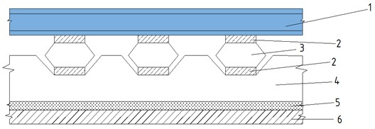
A concrete base has a path consisting of prestressed sleepers with elastic elements as indicated in Fig. 4. Elastic elements are included in the longitudinal profile to decrease the track stiffness, and also to straighten the track. There are separate and permanent fasteners between the rail and sleeper. The polygonal shape of the reinforced concrete sleeper is done in this manner. Such a form of the sleepers makes it possible to install elastic gaskets and avoid transverse displacement.
Fig. 2Construction at the railway tracks on a continuous prestressed reinforced concrete slab with a rail block: 1 – rails, 2 – sub-rail metal gasket, 3 – gasket - F-4, 4 – sub-rail blocks, 5 – bearing structure, 6 – sand cushion, 7 – sealing base
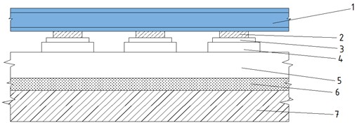
Fig. 3Construction of a railway track with a prestressed concrete foundation: 1 – rails, 2 – sub-rail gasket, 3 – fluoroplastic gasket - F-4, 4 – reinforced concrete bed, 5 – ballast, 6 – sand cushion, 7 – compacted base
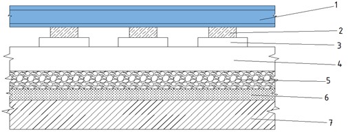
Fig. 4Construction of a railway track with prestressed reinforced concrete sleepers and F-4 railway linings: 1 – rails, 2 – F-4 pads, 3 – prestressed sleepers, 4 – main bearing structure, 5 – sand cushion, 6 – compacted subgrade
4. Results and discussion
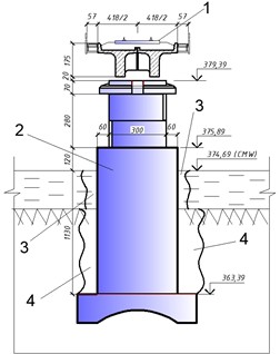
The application of the above-mentioned structures to railway tracks ensures elastic deformation of the railway. The seismic isolation coefficient is determined based on experimental studies and constructions are selected based on the soil type. The experimental scheme for determining the seismic isolation coefficient is presented in Fig. 5.
The seismic force on the bridge structure and the railway is suggested to be calculated using the formula:
where – magnitude of seismic load, (kN); – mass of bridge segment with the surrounding segment of the railroad track, (kN); – seismic coefficient is dependent on the initial seismicity; – dynamism coefficient; – active seismic isolation coefficient, the coefficient of which is experimentally determined.
Fig. 5General schematic view of the test model for determining the seismic isolation coefficient of the railway track soil: 1 – reinforced concrete pile; 2 – earthwork; 3 – weak base soil; 4 – SM-3 sensors, 5 – vibration vibrator (VI-9-8A)
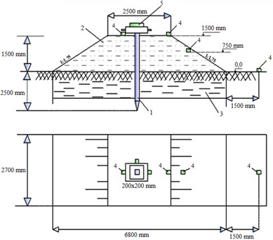
Seismic isolation also does not take place in rocky soils, but its calculated seismicity presents up to 7 points as stated by the Institute of Seismology of the Russian Academy of Sciences. The seismic load on the soil type was depended with the dimension provided in the model diagram of the earthwork embankment. In line with this, there is no damping on rocky soils, and the load influences the structure at 100 percent. Different levels of attenuation of the seismic inertia force are shown in Fig. 6 in water and weak soils.
Fig. 6Graph of the dependence of the seismic load affecting the railway track structure on the change in the physical and mechanical properties of the embankment soil
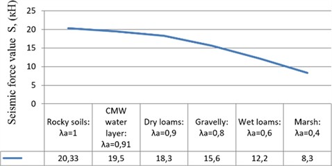
As seen on the graph (Fig. 6), it is feasible to come up with a parabolic dependence of the forces of seismic inertia acting on the railway track setup on the weakening of the physical and mechanical characteristics of the soil on which the bridge crossing supports are situated [3], [4].
Currently, global experience shows that one of the main tasks in designing railway earthworks in complex conditions is to consider seismic forces. When designing with the magnitude of seismic forces, the fact that the soils perform a seismic isolation function depending on the soil type is not taken into account. The results of our research showed that various soils perform a seismic isolation function and were determined using a graphical experiment presented in Fig. 6.
The findings of our investigation enable us to explain seismic inertial loads on reinforced concrete, pile, or column supports of bridges, and thanks to the implementation of the offered structures of railways (Fig. 1-4) it is possible to decrease the percentage of reinforcement of bridge supports to 30-percent based on the characteristics of the foundation soil. Fig. 7 illustrates the seismic wave scheme of propagation in the transverse direction with respect to the axis of the railways.
Fig. 7Directions of propagation of seismic and vibrodynamic vibration waves relative to the railway tracks: 1 – railway track, 2 – bridge supports, 3 – damping layer of water, 4 – damping layer of soil
In the junction zone of the bridge and the earthwork, which is one of the complex sections, the values of the oscillations are different. Considering this, it is possible to achieve a reduction in seismic and vibrodynamic impacts by reinforcing the embankment with reinforced concrete piles. The scheme for driving a reinforced concrete pile into the embankment is shown in Fig. 8.
Fig. 8A scheme for driving reinforced concrete piles to reduce the impact of seismic and vibrodynamic forces on the railway track structure in complex conditions: 1 – coastal support, 2 – reinforced concrete pile, N – vertical pressure, Rs – base reaction force, L – length of the reinforced concrete pile, α – angle of inclination of the reinforced concrete pile to the vertical
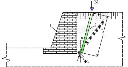
Based on the above diagram, in the junction zone between the earthwork and the bridge, reinforced concrete piles are driven into the railway earthwork, achieving increased embankment soil rigidity. Stamping a reinforced concrete pile in the embankment reduces the impact of seismic and vibrodynamic forces on the earthwork, ensuring the safe operation of the railway tracks.
Consequently, considering that the earthworks extinguish seismic waves, it is possible to increase the distance between reinforced concrete piles. The mathematical expression for calculating the distance between reinforced concrete piles driven into the embankment soil in the junction zone of the railway track and the bridge is given in Eq. (2):
where – width of the railway track, m; – embankment height, m; – dynamic coefficient which puts into consideration the soils characteristics; – coefficient which considers the speed of the trains; – active seismic isolation coefficient, the figure of which is equivalent to: 1.2 under strong ground foundations; 1.1 under weak ground foundations. The values of the above expressions and coefficients were determined as a result of the experiment in the model presented in Fig. 5.
The application of the proposed designs and seismic isolation coefficient in various soils during the railway design process will increase seismic resistance and reduce costs. An economically justified design for increasing the strength of the railway track in difficult conditions has also been proposed.
5. Conclusions
1) In complicated relief conditions, when the soils are rather weak, the damage of the trackway is possible even during the earthquake with the intensity of 5-6 points or due to the impact of high-speed trains traffic which also causes the seismic vibrations.
2) In calculating the seismic loads on the railway tracks, real conditions should be taken into consideration to enable, justify and minimize economic costs in the process of construction.
3) When the trains are traveling rapidly, when the high embankments of the earthen floor are strengthened with the help of reinforced concrete piles the soil of the embankment and the base absorbs the amplitude frequency fluctuations of the rolling stock up to 15 %.
References
-
M. Mekhmonov and A. Uralov, “Reducing impact of embankment soils on shore support of bridge on the approaches to bridges,” E3S Web of Conferences, Vol. 401, p. 02040, Apr. 2023, https://doi.org/10.1051/e3sconf/202340102040
-
A. Abdujabarov, M. Mekhmonov, P. Begmatov, F. Eshonov, and M. Khamidov, “Consideration of the environmental impact on the seismic inertial forces of the railway track in difficult conditions,” in AIP Conference Proceedings, Vol. 3045, p. 030097, Jan. 2024, https://doi.org/10.1063/5.0197332
-
M. Mekhmonov, S. Makhamadjonov, and A. Uralov, “Stabilization of embankments and coastal bridges with reinforced concrete piles,” E3S Web of Conferences, Vol. 508, No. 9, p. 08018, Apr. 2024, https://doi.org/10.1051/e3sconf/202450808018
-
M. Mekhmonov, S. Makhamadjonov, and A. Uralov, “Efficiency of reinforcement of transition sections on the railroad by the developed constructions,” E3S Web of Conferences, Vol. 508, No. 9, p. 08017, Apr. 2024, https://doi.org/10.1051/e3sconf/202450808017
-
Z. Zhang, G. Yan, and C. Xu, “Seismic responses of underground structures based on centrifuge shaking table test in liquefiable site,” Chinese Journal of Geotechnical Engineering, Vol. 47, No. 2, pp. 324–336, Jan. 2025, https://doi.org/10.1007/s11803-024-2272-6
-
H. Li, Z. Hu, T. Zhong, H. Qin, X. Ji, and L. Zhou, “Seismic fragility and life-cycle loss analyses of high-speed railway bridges supported by segmentally assembled round-end hollow piers,” Earthquake Engineering and Resilience, Vol. 3, No. 4, pp. 594–611, Apr. 2024, https://doi.org/10.1002/eer2.99
About this article

The authors have not disclosed any funding.
The datasets generated during and/or analyzed during the current study are available from the corresponding author on reasonable request.
The authors declare that they have no conflict of interest.
