Abstract
Traditional main shaft rolling bearings often experience localized stress concentration, transient overheating, and fatigue spalling under low-speed, heavy-load, and variable-speed operating conditions, making it difficult to meet long-life service requirements. To address this issue, this paper proposes a novel hybrid rolling-sliding bearing structure with a parallel design of rolling and sliding bearings, and investigates its operational performance through simulation. Via parameter optimization, the length-to-diameter ratio of the sliding bearing is determined as 1.4, and the initial radial clearance as 400 μm. The results show that under two typical operating conditions of 8 rpm and 10 rpm, the sliding bearing system can achieve a static equilibrium state. Based on the Reynolds equation and its static equilibrium conditions, the eccentricity ratio and attitude angle of the sliding bearing at the static equilibrium position are determined. These parameters are then applied as the eccentric parameters of the bearing bush in the design of the hybrid bearing structure. Consequently, once the hybrid bearing transitions from the start-stop phase to stable operation, the sliding bearing can generate hydrodynamic effects and effectively share the radial load, thereby significantly reducing the radial load borne by the rolling bearing. By adopting a parallel load-carrying structure of rolling and sliding bearings, the modified rating life of the rolling elements within the hybrid bearing under load-sharing conditions reaches approximately 43.52 years at 8 rpm and 35.43 years at 10 rpm, corresponding to improvement factors of 4.9 and 5.0, respectively, compared to the pure rolling bearing, which exhibits 8.89 years at 8 rpm and 7.11 years at 10 rpm. Furthermore, over the operating speed range of 3 to 16 rpm, the average Modified rating life of the rolling elements within the hybrid bearing under load-sharing conditions is approximately 23.58 years for the design based on 8 rpm eccentricity parameters and approximately 23.79 years for the design based on 10 rpm eccentricity parameters, compared to 9.55 years for the pure rolling bearing. The service life of the system is markedly improved, meeting the long-life operation requirements of wind turbines.
Highlights
- A novel rolling-sliding hybrid bearing structure for 10 MW wind turbine main shafts is proposed, featuring a parallel layout of rolling bearings and an eccentric sliding bearing bush.
- Based on Sommerfeld number analysis, the optimal design parameters are determined: a length-to-diameter ratio of 1.4 and an initial radial clearance of 400 μm.
- By forming a convergent wedge clearance via an eccentric bushing, an effective hydrodynamic film is established at 8 rpm, with a maximum pressure of 1.95 MPa and a minimum film thickness of 242.1 μm.
- Under load-sharing conditions, the modified rating life of rolling elements in the hybrid bearing reaches 43.52 years at 8 rpm, which is 4.9 times that of the pure rolling bearing (8.89 years).
1. Introduction
With the steady advancement of the “dual carbon” goals, China’s installed wind power capacity has continued to grow rapidly, and wind turbines have shown a clear trend towards offshore deployment and increasing power ratings [1]. As one of the core components of wind turbines, the main shaft bearing typically needs to meet the demanding standards of over 20 years of fault-free operation and a reliability requirement exceeding 95 %, imposing extremely high criteria on its lifespan and reliability [2-4]. To meet this demand, rolling bearings, a key foundational component of wind power equipment, must also evolve towards longer life, higher load-carrying capacity, and greater reliability [5]. Currently, damage to large-size roller bearings has become one of the main failure modes in wind turbines. This is primarily due to the more severe operating conditions faced by main shaft support bearings as the size and weight of generating units increase [6]. Therefore, the trend towards larger wind turbines presents increasingly severe challenges to the structural configuration and comprehensive performance of main shaft bearings.
In response, extensive research has been conducted across several key areas. In the field of bearing life prediction and reliability assessment, studies have integrated theoretical models, international standards, and simulation tools. Liang Yong et al. [7] considered the actual operating conditions of the main shaft bearing under radial and axial loads. Based on ANSYS and fatigue theory, they predicted a main shaft bearing life of 24.07 years, meeting the 20-year design requirement. Niu Baozhen et al. [8] focused on the fixed-end bearing of a 4.5 MW wind turbine main shaft. They established a fatigue life theoretical model based on ISO 281:2007 and the Palmgren–Miner linear damage accumulation theory. By comparing the ISO 281 modified algorithm with Romax model simulations, they found that both methods align more closely with actual operating conditions. Jia Xianzhao et al. [9] proposed a numerical simulation method based on ANSYS Workbench and ANSYS nCode DesignLife for predicting the fatigue life of wind turbine main shaft bearings. The validity of this method was verified by an error margin of 5.3 % compared with theoretical calculations. Kenworthy et al. [10] contributed to this discourse by evaluating main bearing rating lives in accordance with IEC 61400-1 and ISO 281 standards. Although predicted lives for large bearings significantly exceeded the 20-year requirement, their study highlighted that such standard assessments fail to explain the high failure rates observed in 1-3 MW turbines, indicating a gap between theoretical models and field experience.
Research on structural mechanics, friction, and design optimization has focused on improving intrinsic bearing performance. Zhao Wei et al. [11] investigated the influence of structural thickness, friction conditions, and interference conditions on subsurface stresses in the main shaft bearing by establishing a finite element model. The results indicated that increasing the inner ring thickness improves the stress reliability of the bearing, while increases in other parameters, such as outer ring thickness, roller length, and material elastic modulus, reduce the bearing’s stress reliability. Li Jincheng et al. [12] developed an analysis method for the friction torque of a three-row cylindrical roller wind turbine main bearing under combined loads. The results showed that the friction torque of this bearing mainly originates from the axial rollers. Reasonable axial clearance, roller parameters, cage mass, and seal ring interference are highly beneficial for the friction reduction design of this bearing. Zhu Yuteng et al. [13] proposed a bearing performance evaluation method combining classical theory and simulation. Analysis using a flexible model built in Romax indicated that considering component deformation allows for a reasonable calculation of bearing fatigue life, and the optimal crown shape for tapered rollers needs to be determined specifically based on the load. In the realm of tribology and lubrication theory, Edward Hart et al. [14] authored a comprehensive review on elastohydrodynamic lubrication theory for wind turbine main bearings. The article systematically reviews fundamental theories, numerical solution methods, film thickness formulas and their applicability, and explores advanced topics such as lubricant starvation, non-steady effects, and grease lubrication. The authors noted that the numerical models cited have been validated against experimental results, and widely used film thickness formulas typically exhibit small prediction errors within their applicable parameter ranges (for example, some formulas have an average error of about 3.3 %).
In the area of condition monitoring, fault diagnosis, and vibration control, the goal is to enable real-time health assessment and intervention. Liang Yonghong et al. [15] combined fault tree analysis and Bayesian networks to design a fault warning method for the main shaft. Comparative experiments demonstrated that this method can not only effectively monitor abnormal vibrations of the main shaft but also provide real-time warnings for potential faults. Guo Mingjun et al. [16], through establishing a fault model for wind turbine main shaft bearings, analyzed that: when rotational speed increases, it is advisable to use diagnostic indicators related to root mean square (RMS) values; when radial load increases, indicators such as peak-to-peak values are more effective; while dimensional parameters are not suitable as diagnostic indicators. Separately, Breńkacz et al. [17] proposed an automatic imbalance control system using a fluid accumulator to adjust correction masses in real time. Simulations and experiments on a 5 MW model demonstrated its effectiveness in reducing vibrations from sources like blade icing, offering a new approach to enhance drivetrain reliability.
Regarding innovative bearing architecture, novel designs have been proposed to overcome the limitations of conventional bearings. P. G. Panait et al. [18], aiming to improve the reliability of megawatt-class wind turbine main shaft bearings, proposed novel bearing structural schemes based on three and four support points to replace traditional standard bearings. They analyzed failure modes including micro-spalling and insufficient lubrication, ultimately providing criteria and solutions for selecting reliable bearings with long life and low maintenance costs. Tim Schröder et al. [19] proposed a novel tapered sliding bearing for wind turbine main shafts. This bearing features a flexible support structure and a replaceable bearing shell design. Its excellent performance in load-carrying capacity, mixed friction characteristics, and start-up behavior was validated through full-scale bench tests. Roman Polyakov et al. [20-21] proposed two hybrid bearing designs: load-separated (PL) and speed-separated (PS). Hybrid bearings refer to the combination of rolling bearings and sliding bearings. Through both theoretical and experimental verification, they demonstrated that hybrid bearings offer advantages such as extended service life, increased load capacity, reduced friction, improved thermal conditions, and enhanced stiffness and damping characteristics. They also effectively circumvent the inherent drawbacks of single-type bearings, namely the speed limitations of rolling bearings and the rubbing/wear issues of hydrodynamic bearings during start-up and shutdown.
Existing research has made significant progress in the life analysis, fault diagnosis, and structural optimization of rolling bearings. Meanwhile, the application of sliding bearings in wind turbine main shafts has primarily focused on structural design. Furthermore, while hybrid bearing technology has been studied in fields such as turbomachinery and aerospace, its application in high-power wind turbine main shafts has yet to be reported.
Therefore, this paper proposes an innovative rolling-sliding hybrid bearing structure. This design combines the respective advantages of rolling bearings – such as low starting friction torque and high rotational stability – with the wider operational speed capability of sliding bearings. Simultaneously, it addresses the inherent limitations of each type: the speed constraints of rolling bearings and the rubbing/wear risks of hydrodynamic bearings during start-up and shutdown phases. Based on the lubrication theory for sliding bearings and the fatigue life theory for rolling bearings, this paper systematically analyzes the influence of key design parameters of the hybrid bearing on modified rating life of the rolling bearing under hybrid load-sharing conditions, thereby validating the effectiveness of this hybrid bearing in significantly enhancing overall lifespan.
2. Structural design of the rolling-sliding hybrid bearing
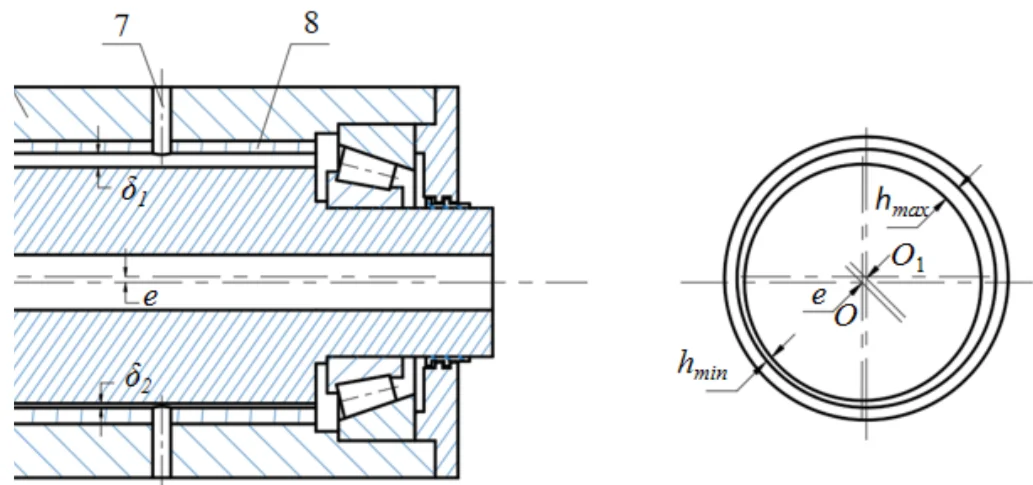
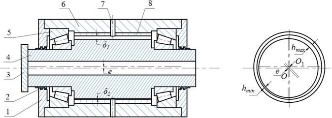
The structure of the rolling-sliding hybrid bearing is shown in Fig. 1, This design employs a pair of coaxially arranged tapered roller bearings installed at both ends of the main shaft. These bearings are responsible for carrying axial and radial loads while providing precise radial positioning. The bearing housing and labyrinth ring together provide axial positioning for the outer rings of the rolling bearings. Additionally, sealing rings are incorporated to ensure sealing performance. The bearing bush is designed with an eccentric structure and is sleeved within the bearing housing to form the tapered clearance necessary for generating the hydrodynamic effect. Here, represents the centerline of the shaft and the outer ring of the bearing bush, while represents the centerline of the inner ring of the bearing bush.
The working principle is described as follows. During the start-stop phase, the main shaft operates at low speed. The hydrodynamic effect is not yet established. Therefore, the external radial load is primarily borne by the rolling bearings. Upon entering stable operation, the main shaft speed increases. Lubricating oil is drawn from the large clearance into the gradually narrowing wedge-shaped region. During this convergent process, sufficient supporting reaction force is generated. This enables the sliding bearing to carry part of the external radial load. The higher the rotational speed, the more pronounced the hydrodynamic effect becomes. The supporting reaction force increases, and a larger share of radial load is assumed. Consequently, the load borne by the rolling bearings progressively decreases.
A load-separated parallel load-sharing structure is adopted by the hybrid bearing. Thus, the radial load distribution satisfies the following mathematical model:
Fig. 1Structure of the rolling-sliding hybrid bearing: 1 – labyrinth ring, 2 – sealing ring, 3 – main shaft flange, 4 – main shaft, 5 – tapered roller bearing, 6 – bearing housing, 7 – oil supply pipe, 8 – bearing bush
3. Mathematical model of the rolling-sliding hybrid bearing
3.1. Mathematical model of the hydrodynamic bearing
The mathematical model of the hydrodynamic bearing is based on the theory of hydrodynamic lubrication. The reaction force of a conventional hydrodynamic bearing is obtained by integrating the pressure distribution over the bearing surface. The pressure distribution must be determined by numerically solving the Reynolds equation. According to reference [22], the Reynolds equation for an incompressible fluid in a radial bearing is given by:
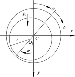
where: is the unknown pressure distribution function; is circumferential coordinate; is axial coordinate; is radial clearance function: ; , are the density and dynamic viscosity of the lubricant; is the circumferential velocity distribution: ; is the rotor angular velocity; , are the velocities of the journal center in the coordinate system; is the velocity distribution in the radial direction on the surface of the journal: . The coordinate system and parameter definitions of the sliding bearing are shown in Fig. 2.
The load-carrying capacity is calculated based on the pressure field distribution:
where, is oil film pressure distribution function; is the bearing radius.
The total load-carrying capacity is:
Fig. 2Sliding bearing coordinate system and parameter definitions
The frictional torque of a hydrodynamic bearing primarily depends on the sliding velocity. Therefore, the frictional torque is:
3.2. Fatigue life model of tapered roller bearings
The fatigue life of the bearing involves the calculation of the rated roller load, roller load distribution, and equivalent roller load. Under normal operating conditions, the basic reference rated life of the bearing corresponding to 90 % reliability is:
where: is the basic dynamic load rating (N); is the equivalent dynamic load (N); – operating speed (rpm).
The formula for calculating the equivalent dynamic load is as follows:
where, is the radial dynamic load coefficient and is the axial dynamic load coefficient.
For a double-row tapered roller bearing, the basic dynamic load rating is:
where: ; is the bearing type correlation coefficient; is the number of rolling elements; is a material coefficient; is the effective length of the roller; is the roller diameter; is the number of rows, is the contact angle.
Based on the basic rated life, modifications are applied to account for load magnitude, bearing speed, lubricant viscosity, and contamination levels. This yields the modified rated life, which more closely reflects the actual operating conditions of the bearing, expressed as:
where: is the reliability life modification factor and is the life modification factor.
In this study, for ease of presentation, “hybrid bearing life” specifically refers to the modified rating life of the rolling elements within the hybrid bearing under load-sharing conditions, as the sliding component does not undergo rolling fatigue.
4. Analysis of the rolling-sliding hybrid bearing characteristics
During the transition from shutdown to stable operation, dynamic load-sharing characteristics are exhibited by the hybrid bearing. To investigate whether this capability extends the service life of the rolling bearing, a simulation analysis is conducted. The load input parameters are shown in Table 1.
Table 1Load input parameters
Load parameter | Value |
Radial load | 4000 kN |
Axial load | 6000 kN |
4.1. Analysis of hydrodynamic characteristics in the hybrid bearing
The Sommerfeld number () is a dimensionless number that describes the relationship between the load borne by the bearing, the viscosity of the lubricant, the rotational speed, and other comprehensive factors relative to the geometric dimensions of the bearing. Its calculation formula is as follows:
where: is the journal radius; is the dynamic viscosity of the lubricating oil; is the shaft rotational speed; is the average pressure on the projected bearing area; , is the total load; is the bearing length; is the bearing diameter.
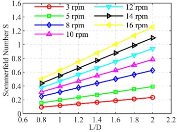
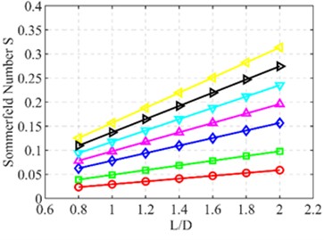
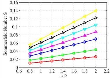
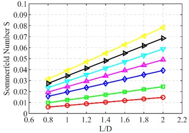
Based on lubrication characteristic analysis, a reasonable range for the length-to-diameter ratio and initial radial clearance was determined. The calculated Sommerfeld numbers under different initial oil film thicknesses are shown in Fig. 3.
As shown in Fig. 3, a significant increase in S is observed with increases in the length-to-diameter ratio and rotational speed. When the ratio increases from 1.0 to 1.4 under the same conditions, rises from 0.196 to 0.274. With a fixed initial oil film thickness of 400 µm, an increase from 3 rpm to 12 rpm causes to increase from 0.0294 to 0.118. Conversely, a noticeable decrease in is observed as the initial oil film thickness increases. When expands from 200 µm to 800 µm, drops sharply from 0.118 to 0.00735.
Considering the low-speed and heavy-load operating conditions of wind turbine main shafts, to ensure that the bearing operates in the hydrodynamic lubrication regime, S should be greater than 0.05. Therefore, the initial oil film thickness should be in the range of 200-600 μm, and the length-to-diameter ratio is preferably controlled within 1.4-1.8. Taking into account the compatibility of the sliding bearing with the rolling bearing in the wind turbine main shaft, the length-to-diameter ratio should not be excessively large. In this paper, a length-to-diameter ratio of 1.4 is adopted.
Simulation parameters are based on the actual operating conditions of a 10 MW wind turbine main shaft. Since the oil supply pressure is extremely low, a value of 0 is used. The specific values are shown in Table 2.
Fig. 3Variation of Sommerfeld number with length-to-diameter ratio and rotational speed: a) c= 200 µm, b) c= 400 µm, c) c= 600 µm, d) c= 800 µm
a)
b)
c)
d)
Table 2Bearing input parameters
Bearing parameter | Value |
Bearing diameter | 1720 mm |
Radial load | 4000 kN |
Inlet oil pressure | 0 |
Length-to-diameter ratio | 1.4 |
Lubricant grade | VG320 |
Bearing width | 2408 mm |
Oil supply temperature | 50 ℃ |
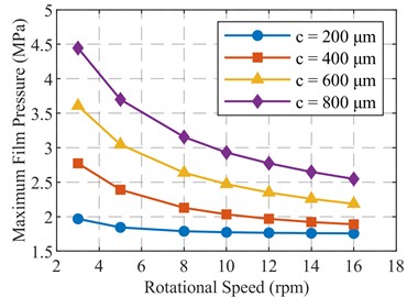
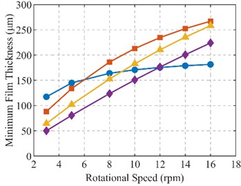
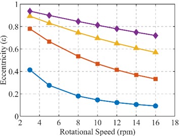
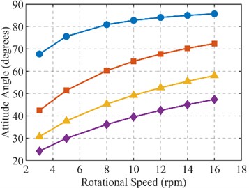
To determine the geometric parameters of the eccentric bearing bush structure, this study systematically analyzed the effects of different radial clearances and rotational speeds on the bearing lubrication performance. The investigation focused on the dynamic response characteristics of the maximum oil film pressure, minimum oil film thickness, eccentricity ratio, and attitude angle. The results are shown in Fig. 4.
At a fixed rotational speed, an increase in the maximum oil film pressure is observed with enlargement of the radial clearance. For example, at 8 rpm, the pressure rises from 1.79 MPa at 200 µm clearance to 3.16 MPa at 800 µm clearance. This suggests that appropriately increasing the radial clearance significantly elevates oil film pressure. Oil film formation capability and lubrication robustness are thereby enhanced. Overall load-carrying performance is improved. Under the same clearance, a decrease in oil film pressure is noted as rotational speed increases. This indicates that stronger oil film pressure can be generated at lower speeds.
Fig. 4a) Maximum oil film pressure, b) minimum oil film thickness, c) eccentricity ratio, d) attitude angle
a)
b)
c)
d)
The minimum oil film thickness increases with higher rotational speeds. It is substantially greater than typical hydrodynamic bearing oil film thicknesses. At the same rotational speed, an increase in initial clearance from 400 µm to 600 µm results in a decrease in oil film thickness.
Regarding shaft center trajectory, under fixed clearance, the eccentricity ratio decreases as rotational speed increases. Under fixed speed, it increases with larger clearances. For instance, at 8 rpm, the ratio rises from 0.181 (200 µm) to 0.845 (800 µm). The attitude angle increases with higher speeds under the same clearance. It decreases with larger clearances at the same speed.
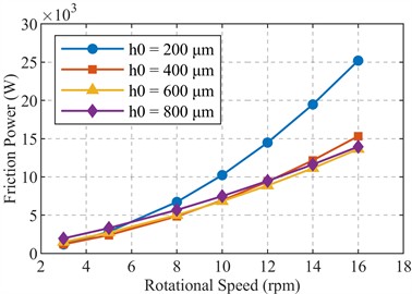
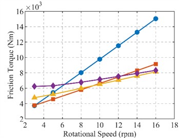
Given the large size and weight, friction torque and frictional power consumption were further analyzed. Their variation with rotational speed and initial clearance is shown in Fig. 5.
Fig. 5a) Bearing frictional power, b) friction torque
a)
b)
As shown in Fig. 5, with the increase in rotational speed, both the friction torque and frictional power consumption exhibit a significant upward trend overall. For instance, with a fixed clearance of 200 µm, when the rotational speed increases from 3 rpm to 16 rpm, the friction torque rises from approximately 3.73 kN·m to about 15.04 kN·m, while the frictional power consumption increases from approximately 1.17 kW to about 25.20 kW. This indicates that the friction is overly sensitive to changes in rotational speed, which can exacerbate bearing wear. To balance lubrication performance and friction losses, the initial radial clearance should be controlled within the range of 400-800 µm.
Taking all factors into consideration, it is determined that the sliding bearing has a length-to-diameter ratio of 1.4 and an initial radial clearance of 400 μm. The selected radial clearance of 400 μm corresponds to a relative clearance of 0.465 ‰ for the 1720 mm diameter bearing. According to ISO 12129-1:2024, the recommended relative clearance range for metal plain bearings is 0.56 ‰-3.15 ‰, while heavy-duty low-speed applications such as rolling mills typically adopt 0.5 ‰-1.5 ‰. The value of 0.465 ‰ is slightly below these ranges, which is reasonable for the ultra-low-speed conditions of 8 to 10 rpm and the heavy-load condition of 4000 kN considered in this study. Additionally, ISO 5753-1991 indicates that radial internal clearances for comparably sized rolling bearings range from 330 μm to 1450 μm, confirming the technological feasibility of 400 μm.
To further address the effect of manufacturing tolerances and assembly deviations, a sensitivity analysis was performed for radial clearances of 350 μm, 400 μm, and 450 μm under the same operating conditions (8 rpm and 10 rpm, radial load 4000 kN, / 1.4). The results are summarized in Table 3.
Table 3Sensitivity analysis results for different radial clearances
Clearance (μm) | Speed (rpm) | Minimum film thickness (μm) | Maximum pressure (MPa) |
350 | 8 | 237.7 | 1.88 |
400 | 8 | 242.1 | 1.95 |
450 | 8 | 241.0 | 2.03 |
350 | 10 | 257.0 | 1.84 |
400 | 10 | 267.0 | 1.89 |
450 | 10 | 270.8 | 1.95 |
In all cases, the minimum oil film thickness remains above 230 μm, which is two orders of magnitude larger than typical surface roughness of approximately 1 μm. Thus, full-film lubrication is maintained across a clearance band of ± 50 μm around the nominal 400 μm value. The maximum pressure varies by less than 8 %, indicating that load-carrying capacity is not highly sensitive to moderate clearance deviations.
Moreover, the operating speed is extremely low, ranging from 3 to 16 rpm, so centrifugal forces and dynamic unbalance are negligible. Small geometric deviations do not induce significant pressure fluctuations. The pressure field is dominated by the convergent wedge geometry, which is not critically affected by moderate misalignment or roundness errors. Additionally, the shaft with a diameter of 1500 mm and the housing with an outer diameter of 1820 mm have very large cross-sections, providing high structural stiffness. Elastic deformations under the applied loads are extremely small and do not compromise the clearance distribution or load-sharing mechanism.
Consequently, within a realistic manufacturing tolerance band of ± 50 μm, which corresponds to IT7-IT8 grade for a bearing of this diameter, the hybrid bearing’s lubrication performance and load-sharing capability remain effective. The nominal clearance of 400 μm is therefore a well-justified design choice for the ultra-low-speed, heavy-load conditions of a 10 MW wind turbine main shaft.
It should be emphasized that the nominal radial clearance of 400 μm used in this study represents an ideal geometric value. Manufacturing tolerances, deviations in roundness and alignment, assembly inaccuracies, and housing deformations are not considered in the present analysis. A detailed tolerance analysis is beyond the scope of this work, which focuses on the fundamental feasibility and performance potential of the hybrid bearing under idealized nominal conditions. Therefore, the results presented herein should be interpreted as an upper-bound estimate of load-sharing capability and life extension. Future work should include tolerance analysis and experimental validation.
According to reference [23], since the main shaft bearing operates at speeds ranging from 0 to 16 rpm, this study conducts simulation analyses at radial clearances of 400 μm and rotational speeds of 8 rpm and 10 rpm to validate the hydrodynamic effect of the sliding bearing.
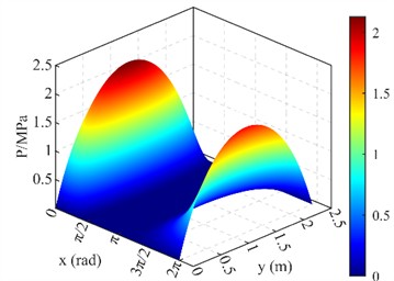
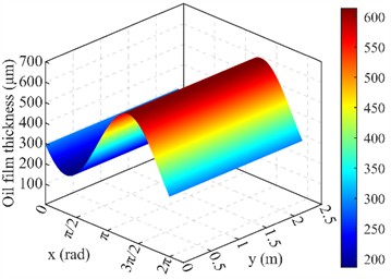
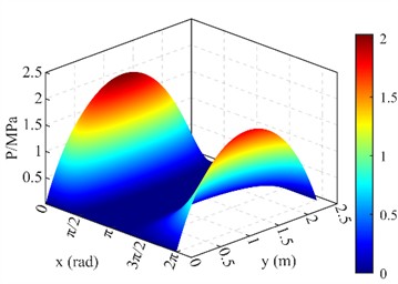
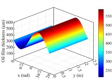
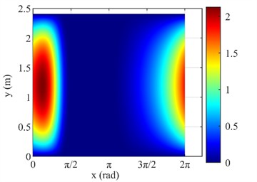
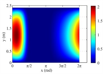
Fig. 6Simulation results for pressure and film-thickness distributions (radial load F acts vertically along the positive Y-axis, with circumferential coordinate φ= 0 corresponding to the load line): a) 3D oil film pressure distribution at 8 rpm; b) 3D oil film thickness distribution at 8 rpm; c) 3D oil film pressure distribution at 10 rpm; d) 3D oil film thickness distribution at 10 rpm; e) 2D planar unwrapped pressure distribution at 8 rpm; f) 2D planar unwrapped pressure distribution at 10 rpm
a)
b)
c)
d)
e)
f)
Based on the simulation analysis from Fig. 6, the results indicate that at 8 rpm, the minimum oil film thickness is approximately 242.1 µm, demonstrating that the bearing operates under a thick-film lubrication condition. Simultaneously, the maximum oil film pressure is about 1.95 MPa. Under these operating conditions, the corresponding eccentricity ratio is approximately 0.395, and the attitude angle is about 68.8°. When the rotational speed increases to 10 rpm, the minimum oil film thickness rises to 267.0 µm, indicating a further thickening of the lubricating film. The maximum oil film pressure slightly decreases to 1.89 MPa, suggesting a more gradual load distribution. Under these conditions, the bearing bush eccentricity ratio decreases to approximately 0.332, while the attitude angle increases to about 72.4°.
The oil film pressure distribution shown in Fig. 6 exhibits near-perfect circumferential symmetry. This result stems from the rigid-shaft assumption, which requires the operating speed n to be significantly lower than the first critical speed (typically / ≲ 0.3). To justify this assumption for the specific shaft-bearing system, a conservative estimate of is provided.
The main shaft is stepped. Taking the smallest diameter (1500 mm, at the rolling bearing mounting position) as the reference diameter, and using the length-to-diameter ratio of 1.4, the shaft length is 2100 mm. The cross-sectional moment of inertia is 0.2485 m4, and the shaft mass is 29100 kg. For such a short-thick shaft ( 1.4), the Euler-Bernoulli beam model is invalid because shear deformation and rotary inertia dominate. Instead, the Timoshenko beam model and engineering experience for megawatt-scale wind turbine main shafts indicate that the first critical speed lies in the range of 50-150 rpm. Owing to the extremely large diameter and high bending stiffness, the first critical speed of this shaft is at the upper end of this range, approximately 150 rpm. This is six times the maximum operating speed of 25 rpm, well satisfying the rigid-shaft condition.
Under the rigid-shaft, purely radial loading, and ideal alignment assumptions adopted herein, the present simulations show high load-sharing ratios, reaching 98.43% at 8 rpm and 99.23% at 10 rpm. However, the influence of shaft flexibility, bending moments, misalignment, and non-uniform support conditions on the load-sharing mechanism has not been investigated and requires verification in future work. It should be emphasized that these results are obtained under nominal conditions; actual performance under more realistic conditions may differ.
Based on the above reasoning, the idealized rigid-shaft model provides an upper-bound estimate of load-sharing and life extension under nominal conditions. Further quantitative investigation using flexible-shaft models, including bending moments, misalignment, and non-uniform support conditions, is required to assess the performance under more realistic operating conditions.
The total radial load on the hybrid bearing remains constant, yet the distribution ratio between the rolling elements and the sliding bearing shell is determined by the shell's eccentric design. This passive load-sharing mechanism, resulting from the eccentric bush geometry and hydrodynamic pressure generation, enables dynamic load variation without active control. Consequently, the aforementioned eccentricity parameters are identified as key determinants in establishing the structural configuration of hybrid rolling-sliding bearing shells.
4.2. Analysis of life characteristics of the rolling-sliding hybrid bearing
The rolling bearing in the wind turbine main shaft includes the bearing inner ring, outer ring, and rolling elements. The design parameters of the tapered roller bearing are shown in Table 4.
In practical wind turbine applications, tapered roller bearings are mounted with a light axial preload achieved by axial spacer adjustment. This preload is commonly applied in large-scale wind turbine main shafts to eliminate internal radial clearance and ensure positioning accuracy. Under this preload, the internal radial clearance of the rolling bearing is effectively reduced to within ±2 μm. It should be emphasized that this clearance refers to a different physical interface than the sliding bearing’s nominal 400 μm concentric radial clearance; therefore the two clearances do not conflict. The load-sharing mechanism does not require relative radial motion between the rolling bearing inner and outer rings; it relies only on the static eccentric geometry of the sliding bearing bush, making the proposed design geometrically feasible.
Table 4Design parameters of the tapered roller bearing
Design parameter | Value |
Bearing bore diameter | 1500 mm |
Bearing outer diameter | 1820 mm |
Roller effective length | 137 mm |
Number of rolling elements | 55 |
Contact angle | 45° |
Roller large-end diameter | 82.5 mm |
Roller small-end diameter | 77.5 mm |
The total radial load is shared between the rolling bearing and the sliding bearing as . This relationship holds regardless of the rolling bearing’s internal clearance or preload. When the shaft reaches an operating speed of 8 to 10 rpm, the sliding bearing develops a full-film hydrodynamic pressure due to its eccentric bush geometry, automatically carrying a large portion of the radial load: 98.43 % at 8 rpm and 99.23 % at 10 rpm, as shown above. Consequently, becomes very low, namely 1.57 % and 0.77 % of the total radial load, respectively, whether the rolling bearing has a small clearance after preload or a larger clearance.
Regarding the effects of preload on friction, heat generation, equivalent dynamic load, and bearing life, the preload effect is considered negligible for the fatigue life assessment under the specific operating conditions of this study for the following reasons. First, under steady state load-sharing, the rolling bearing carries only 1.57 % or 0.77 % of the total radial load. The additional contact stress caused by preload is much smaller than the residual radial stress and therefore has a negligible impact on fatigue life. Second, the rotational speed is extremely low, ranging from 3 to 16 rpm, so the extra friction torque due to preload is very small and does not significantly affect the bearing's operating condition. Therefore, in the life calculation using ISO 281, preload is not explicitly included as a separate factor; the reported modified lives are conservative estimates without considering the minor beneficial or adverse effects of preload. A detailed preload analysis is beyond the scope of this study and is recommended for future work.
The values of each coefficient are shown in Table 5.
Table 5Coefficient values
Coefficient | Value |
1.1 | |
165.5 | |
1 | |
1.75 |
The coefficients listed in Table 5 are selected according to ISO 281:2007. Here, is the bearing type correlation coefficient, taken as 1.1 for tapered roller bearings; is the material and geometry coefficient, taken as 165.5 for standard bearing steel; is the reliability life modification factor, taken as 1 for 90 % reliability; is the life modification factor based on lubrication condition and contamination level. The selection of 1.75 is justified as follows based on the actual operating parameters provided by our industrial partner. The lubricant is VG320 oil with a supply temperature of 50 °C. At this temperature, the kinematic viscosity is approximately 160 mm2/s. The bearing pitch diameter is approximately 1660 mm, and the rotational speed is 8-10 rpm. According to the reference viscosity estimation formula in ISO/TR 1281-2, the required kinematic viscosity for the bearing under these conditions is calculated as approximately 70 mm2/s. Therefore, the viscosity ratio is approximately 2.28. The oil cleanliness is maintained at ISO 4406 class 16/13/10, which corresponds to a contamination factor of approximately 0.9-1.0 based on ISO 281:2007 Annex A. For a roller bearing with 2.28 and 0.9-1.0, the life modification factor is determined as 1.75 according to the standard procedure.
The dynamic load distribution mechanism of the rolling-sliding hybrid bearing lies in the fact that during the start-stop phase of the wind turbine main shaft, both radial and axial loads are borne by the rolling bearings. Upon entering stable operation, the sliding bearing forms a complete load-bearing oil film through the hydrodynamic effect, thereby beginning to share the radial load. The key to this design is that the sliding bearing bush is eccentrically arranged, with its eccentricity ratio and attitude angle determined based on the operating condition where the bearing can independently establish full-film lubrication and thereby carry the entire radial load at the target rotational speed. Under the adopted idealized assumptions of a rigid shaft, perfect alignment, and steady-state operation, the sliding bearing can assume nearly the entire radial load, and the radial load on the rolling bearings is reduced to a very low value close to zero, i.e., nearly full unloading. Specifically, at the design condition of 8 rpm, the rolling bearing residual radial load is 62.8 kN, which is only 1.57 percent of the total radial load of 4000 kN, and the sliding bearing carries the remaining 98.43 percent. At 10 rpm, the rolling bearing residual radial load is 30.73 kN, which is only 0.77 percent of the total load, and the sliding bearing carries the remaining 99.23 percent. These values confirm nearly complete unloading under the idealized assumptions. It should be noted that in real-world applications, manufacturing tolerances, elastic deformation, preload, housing flexibility, transient operation, and changes in load direction may prevent complete radial unloading. Therefore, the reported load-sharing ratios represent an upper-bound estimate under ideal nominal conditions. Based on this mechanism, can be obtained through hydrodynamic simulation according to Eq. (1), thereby deriving the dynamically varying . Since the equivalent dynamic load of the rolling bearings changes dynamically with the radial load-sharing state, the coefficients and in its life calculation are also adjusted accordingly. Finally, the life comparison between the hybrid bearing and the pure rolling bearing is shown in Fig. 7, fully demonstrating the advantage of the hybrid design in enhancing lifespan.
Fig. 7Comparison of modified rating life of the rolling bearing under pure rolling and hybrid load-sharing conditions
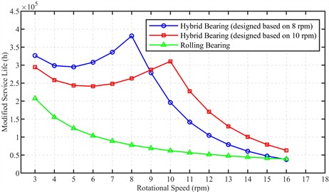
As shown in Fig. 7, the Modified rating life of the hybrid bearing under both design conditions is significantly higher than that of the pure rolling bearing across the entire speed range. The solid blue line represents the hybrid bearing designed based on the eccentricity parameters obtained at 8 rpm; the dashed red line represents the hybrid bearing designed based on the eccentricity parameters obtained at 10 rpm; and the green line represents the modified rating life of the pure rolling bearing. Over the operating speed range of 3-16 rpm, the hybrid bearing exhibits a distinct trend: its modified rating life increases rapidly to a maximum at 8 rpm, then gradually decreases with further speed increase. In contrast, the pure rolling bearing shows a continuous and slow decline across the entire speed range. This fully demonstrates the advantage of the hybrid design in enhancing lifespan.
At 8 rpm with an initial radial clearance of 400 μm, the hybrid bearing achieves a modified rating life of 43.52 years, which is 4.9 times that of the pure rolling bearing with a life of 8.89 years. At 10 rpm, the hybrid bearing achieves a modified rating life of 35.43 years, representing a 5.0-fold improvement over the pure rolling bearing with a life of 7.11 years.
Table 6Modified rating life of pure rolling and hybrid bearings under different operating conditions
Operating speed | Bearing type | Modified rating life (h) | Modified rating life (years) |
8 rpm | Pure rolling | 77,860 | 8.89 |
Hybrid | 381,208 | 43.52 | |
10 rpm | Pure rolling | 62,287 | 7.11 |
Hybrid | 310,407 | 35.43 | |
3–16 rpm avg. (design based on 8 rpm) | Pure rolling | 83,676 | 9.55 |
Hybrid (rolling part) | 206,521 | 23.58 | |
3–16 rpm avg. (design based on 10 rpm) | Pure rolling | 83,676 | 9.55 |
Hybrid (rolling part) | 208,349 | 23.79 |
Such a remarkable lifespan enhancement arises from the optimized eccentricity design of the bearing bush, which nearly fully unloads the radial load on the rolling elements under these operating conditions. The results clearly validate the significant advantages of the dynamic load-sharing mechanism and provide a reliable reference for wind turbine bearing applications.
5. Conclusions
Focusing on the requirements for long lifespan and high reliability, a rolling-sliding hybrid bearing design concept is proposed and numerically investigated in this paper. The main conclusions are drawn as follows:
1) A conceptual design of a rolling-sliding hybrid bearing suitable for 10 MW-class wind turbine main shafts has been proposed. By actively constructing a converging wedge-shaped clearance through an eccentric bearing bush, numerical simulations indicate that an effective hydrodynamic lubrication film is predicted to form at 8 rpm, with a calculated maximum pressure of approximately 1.95 MPa and a minimum film thickness of approximately 242 µm. This suggests the potential for achieving stable lubrication under idealized low-speed, heavy-load conditions, thereby offering a possibility of mitigating direct contact wear between sliding surfaces.
2) The hybrid bearing adopts a parallel layout of rolling and sliding bearings. During start-stop, the radial load is fully supported by the rolling bearings; under steady operation, numerical results show that a significant portion of the radial load can be dynamically transferred to the sliding bearing, substantially reducing the equivalent load on the rolling elements. For the hybrid bearing designed based on the 8 rpm eccentricity parameters, the rolling bearing within it achieves a calculated modified rating life of 43.52 years at 8 rpm under load-sharing conditions, which is approximately 4.9 times that of the pure rolling bearing at 8.89 years. For the hybrid bearing designed based on the 10 rpm eccentricity parameters, the rolling bearing within it achieves a calculated modified rating life of 35.43 years at 10 rpm under load-sharing conditions, which is approximately 5.0 times that of the pure rolling bearing at 7.11 years. Over the operating speed range of 3 to 16 rpm, the average calculated modified rating life of the rolling bearing under load-sharing conditions is 23.58 years for the design based on 8 rpm parameters and 23.79 years for the design based on 10 rpm parameters, both higher than the pure rolling bearing’s average life of 9.55 years, preliminarily indicating a positive effect of this load-sharing mechanism on bearing life extension.
3) The results indicate that the radial clearance and length-to-diameter ratio of the sliding bearing are important parameters affecting performance. Considering both lubrication characteristics and the modified rating life of the rolling bearing under hybrid load-sharing conditions, and based on the adopted modeling assumptions, an initial radial clearance of 400 μm and a length-to-diameter ratio of 1.4 are preliminarily suggested as a favorable configuration.
It must be emphasized that the pressure distributions and load-sharing results presented in this study are obtained under the rigid shaft assumption, purely radial loading, and perfect alignment. Flexible shaft effects, bending moments, non-uniform support conditions, shaft deflection, and misalignment – which occur in real wind turbine main shaft bearings – are not considered. Therefore, the reported results correspond to an idealized case and should be interpreted as an upper-bound estimate of load-sharing capability and life extension potential. Further investigation using flexible shaft models, including bending moments and misalignment, is required to assess the performance under more realistic operating conditions. Additionally, manufacturing tolerances, assembly deviations, thermal effects, and transient operation have not been included; these aspects are left for future work.
Under the idealized assumptions of this study, the proposed concept shows promising numerical potential for load-sharing and life extension. The performance limitations of single-type bearings are effectively alleviated by this hybrid design in numerical simulations, offering a preliminary exploratory pathway for improving main shaft bearing systems in wind turbines of 10 MW and above. However, practical feasibility requires further validation through flexible shaft modelling, tolerance analysis, thermal analysis, and experimental testing.
References
-
Y. Li et al., “Fatigue life calculation of double-support tapered roller bearings for wind turbine main shaft,” (in Chinese), Bearing, Vol. 2023, No. 6, pp. 26–35, 2023, https://doi.org/10.19533/j.issn1000-3762.2023.06.004
-
“The Chinese mechanical engineering technology roadmap-Bearing,” Science and Technology Press, Beijing, Chinese Mechanical Engineering Society, 2011.
-
“Bearing industrial product structure to upgrade the technical route of development and key technology group,” IBIT, 2011.
-
W. Xiao et al., “Load-contact mechanism of double-row tapered roller bearings for large megawatt wind turbine main shafts,” (in Chinese), Machinery Design and Manufacture, Vol. 2021, No. 6, pp. 90–94, 2021, https://doi.org/10.19356/j.cnki.1001-3997.2021.06.021
-
Q. Han et al., “Technological progress in high-power wind turbine bearings,” (in Chinese), Bearing, Vol. 2023, No. 6, pp. 1–13, 2023, https://doi.org/10.19533/j.issn1000-3762.2023.06.001
-
Z. Jiang, X. Huang, H. Zhu, R. Jiang, and S. Du, “A new method for contact characteristic analysis of the tapered roller bearing in wind turbine main shaft,” Engineering Failure Analysis, Vol. 141, p. 106729, Aug. 2022, https://doi.org/10.1016/j.engfailanal.2022.106729
-
Y. Liang, Z. An, and B. Liu, “Fatigue life prediction for wind turbine main shaft bearings,” in International Conference on Quality, Reliability, Risk, Maintenance, and Safety Engineering (QR2MSE), Vol. v.2, pp. 888–893, Jul. 2013, https://doi.org/10.1109/qr2mse.2013.6625711
-
B. Niu et al., “Fatigue life analysis of wind turbine main shaft bearings based on multi-factors,” (in Chinese), Bearing, Vol. 2022, No. 8, pp. 9–14+18, 2022, https://doi.org/10.19533/j.issn1000-3762.2022.08.002
-
X. Jia, J. Ma, and Y. Meng, “Fatigue life calculation of three-row cylindrical roller bearings for wind turbine main shaft based on DesignLife,” (in Chinese), Bearing, Vol. 2018, No. 12, pp. 5–8, 2018, https://doi.org/10.19533/j.issn1000-3762.2018.12.002
-
J. Kenworthy et al., “Wind turbine main bearing rating lives as determined by IEC 61400‐1 and ISO 281: A critical review and exploratory case study,” Wind Energy, Vol. 27, No. 2, pp. 179–197, Nov. 2023, https://doi.org/10.1002/we.2883
-
W. Zhao, Z. Jiang, P. Zhang, and X. Huang, “Reliability sensitivity analysis of main shaft bearings of wind turbines subject to subsurface stress,” Machines, Vol. 11, No. 7, p. 681, Jun. 2023, https://doi.org/10.3390/machines11070681
-
J. Li, Y. Li, and Z. Zhong, “Friction torque analysis of three-row roller main bearing for wind turbines under combined loads,” (in Chinese), Acta Energiae Solaris Sinica, Vol. 45, No. 10, pp. 597–606, 2024, https://doi.org/10.19912/j.0254-0096.tynxb.2023-0986
-
Y. Zhu et al., “Contact stress and fatigue life analysis of wind turbine main shaft tapered roller bearings based on Romax flexible model,” (in Chinese), Mechanical and Electrical Engineering Technology, Vol. 53, No. 6, pp. 41–46, 2024, https://doi.org/10.3969/j.issn.1009-9492.2024-00010
-
E. Hart, E. de Mello, and R. Dwyer-Joyce, “Wind turbine main-bearing lubrication – Part 1: An introductory review of elastohydrodynamic lubrication theory,” Wind Energy Science, Vol. 7, No. 3, pp. 1021–1042, 2022, https://doi.org/10.5194/wes-7-1021-2022
-
Y. Liang, Y. Wang, and L. Song, “Failure warning of wind turbine main shaft based on fault tree analysis and Bayesian network,” (in Chinese), Automation Application, Vol. 66, No. 16, pp. 131–132, 2025, https://doi.org/10.19769/j.zdhy.2025.16.036
-
M. Guo, J. Chen, H. Zhang, and S. Jin, “Fault simulation analysis of wind turbine main shaft bearings under strengthened working conditions,” (in Chinese), Modular Machine Tool and Automatic Manufacturing Technique, Vol. 2022, No. 11, pp. 88–91+96, 2022, https://doi.org/10.13462/j.cnki.mmtamt.2022.11.020
-
Breńkacz, R. Rumin, and J. Blaut, “Method for precision automatic unbalance control in wind turbines by continuously adjusting correction mass,” Advances in Science and Technology Research Journal, Vol. 20, No. 2, pp. 212–242, Feb. 2026, https://doi.org/10.12913/22998624/210041
-
P.-G. Panait, M. I. Panaitescu, F.-V. L. Panaitescu, and A.-A. Scupi, “Considerations for increasing the durability of the main shafts bearings of wind turbine,” in Advanced Topics in Optoelectronics, Microelectronics, and Nanotechnologies XI, Vol. 12493, pp. 61–70, Mar. 2023, https://doi.org/10.1117/12.2642084
-
T. Schröder, G. Jacobs, A. Rolink, and D. Bosse, “FlexPad – Innovative conical sliding bearing for the main shaft of wind turbines,” Journal of Physics: Conference Series, Vol. 1222, No. 1, p. 012026, 2019, https://doi.org/10.1088/1742-6596/1222/1/012026
-
R. Polyakov, L. Savin, and A. Fetisov, “Analysis of the conditions for the occurrence of the effect of a minimum of friction in hybrid bearings based on the load separation principle,” Proceedings of the Institution of Mechanical Engineers, Part J: Journal of Engineering Tribology, Vol. 233, No. 2, pp. 271–280, May 2018, https://doi.org/10.1177/1350650118777143
-
R. Polyakov, L. Savin, and D. Shutin, “Reliability improvement of rotor supports by combining rolling-element bearings and fluid-film bearings,” Applied Mechanics and Materials, Vol. 630, pp. 188–198, Sep. 2014, https://doi.org/10.4028/www.scientific.net/amm.630.188
-
H. Guo, S. Cen, and S. Zhang, Design of Cylindrical and Conical Hydrostatic/Hydrodynamic Sliding bearings. Zhengzhou University Press, 2013.
-
P. Wingertszahn, J. Müller, and O. Koch, “Estimation of smearing damage risk in wind turbine main bearings,” Tribology Transactions, Vol. 68, No. 6, pp. 1413–1423, Nov. 2025, https://doi.org/10.1080/10402004.2025.2558966
About this article

This research was funded by Fujian Province External Cooperation Program, grant number 2024I0044.
The datasets generated during and/or analyzed during the current study are available from the corresponding author on reasonable request.
Shengbo Li: conceptualization, validation, supervision, resources, funding acquisition, project administration, writing-review and editing. Siyue Chen: methodology, formal analysis, software, investigation, visualization, writing-original draft, writing-review and editing. Yifan Liu: software, investigation. Yuan Luo: data curation. Roman Polyakov: validation, supervision. Zhaobo Chen: resources, project administration, supervision.
The authors declare that they have no conflict of interest.

