Abstract
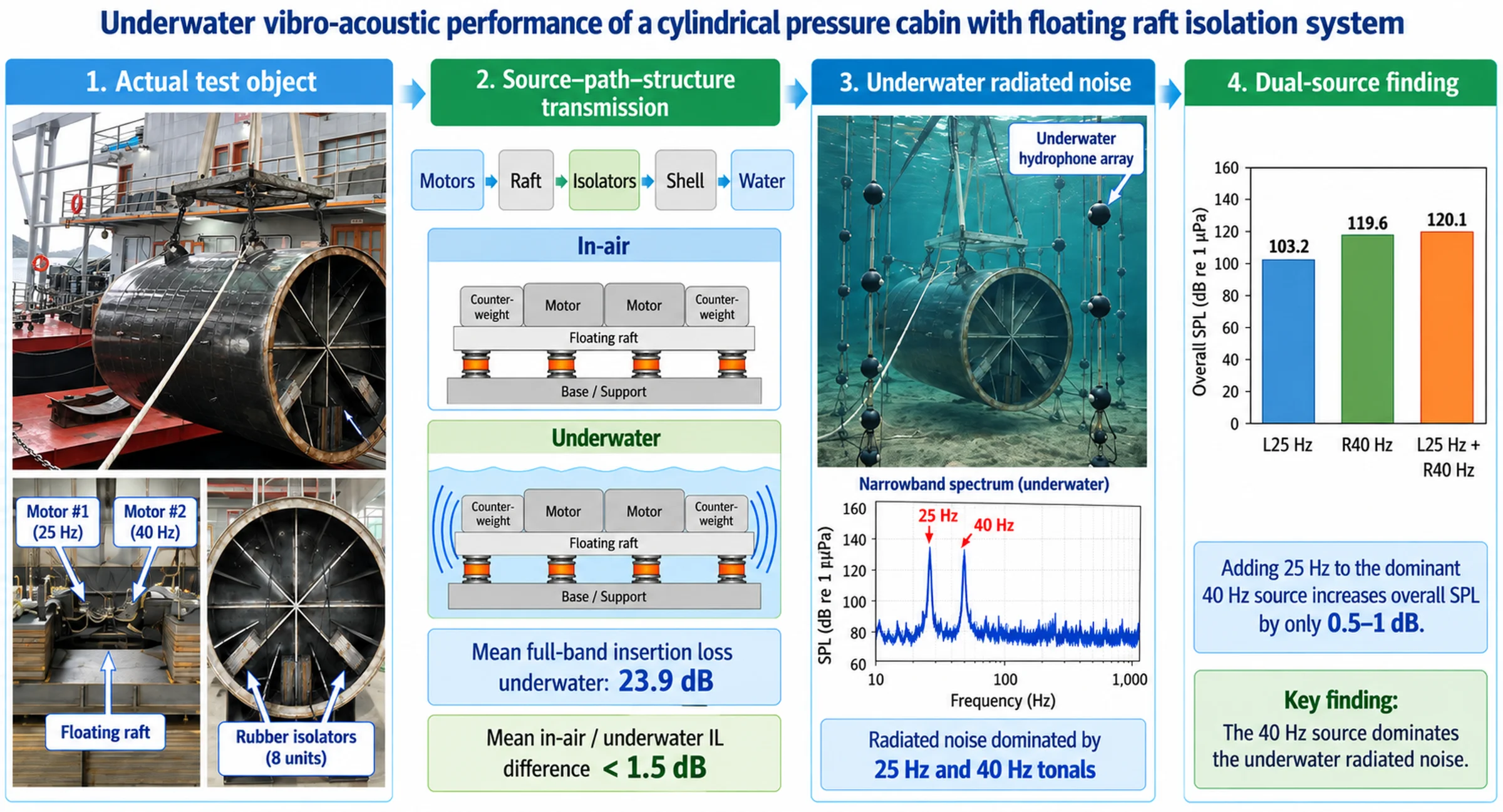
Shipboard equipment vibration is the main source of underwater radiated noise for marine vessels, and floating raft isolation (FRI) systems are widely used for vibration and noise reduction. Current land-based air tests cannot directly reflect the actual isolation performance of FRI systems in underwater service conditions. To address this gap, this paper conducts a systematic experimental study on the vibro-acoustic characteristics of a typical ship cylindrical cabin with an FRI system, in both air and underwater environments. The vibration transfer laws and underwater radiated noise characteristics of the structure are obtained, and the isolation performance of the FRI system is quantitatively evaluated. The research results can provide a direct experimental basis and reference for the design, test, and optimization of marine vibration isolation systems. Compared with previous studies that mainly considered bare or simply stiffened shells, or evaluated floating raft isolation through numerical or air-based tests, this work tests an integrated vibration source to raft with isolator to stiffened-shell to water configuration and provides source-path-receiver benchmark data for assessing the environmental robustness of FRI systems.
Highlights
- Air-water tests characterize an integrated floating raft-shell system.
- Floating raft isolation substantially attenuates underwater vibration transmission.
- Air-water differences in isolation performance remain small.
- Low-frequency excitation tones dominate underwater radiated noise.
- Adding 25 Hz excitation causes only a slight SPL increase over 40 Hz alone.
1. Introduction
Underwater radiated noise primarily originates from three sources: propeller noise, hydrodynamic noise, and machinery noise [1, 2]. With advancements in noise reduction technologies, propeller noise at low speeds has been effectively mitigated, rendering machinery noise generated by onboard equipment (e.g., main engines, auxiliary machinery, pumps) and the subsequent “structure-borne sound” radiated into the water via hull vibration induced by such machinery, a particularly prominent contributor in the low-to-mid frequency range (typically below 1 kHz) [3, 4]. Consequently, suppressing structure-borne sound radiation is a critical challenge for achieving profound acoustic stealth.
To address this challenge, vibration isolation technology is widely employed. Among various solutions, the floating raft isolation (FRI) system represents one of the most advanced passive isolation strategies [5,6]. Its fundamental principle involves mounting major vibrating equipment onto a rigid intermediate mass (the “raft”), which is then connected to the hull structure via a set of isolators. This “equipment-raft-isolator-hull” series configuration creates a two-stage isolation: the first stage is the local isolation between the equipment and the raft (sometimes achieved through equipment mounts), and the second stage is the global isolation between the raft and the main hull [7]. Theoretically, this design not only leverages the mass effect of the raft to reduce transmissibility but also effectively attenuates broadband vibration and suppresses the “jumping” modes resulting from the coupled vibration of multiple equipment through careful design of the isolators' stiffness and damping distribution [8].
Although theoretical modeling, dynamic analysis, and optimization design of FRI systems have been extensively reported in the literature [9-12], and numerical simulation techniques are now capable of handling complex coupled systems [13, 14], a significant gap remains: systematic and detailed experimental investigations on the vibro-acoustic performance of complete FRI systems in a realistic underwater environment are still relatively scarce. The accuracy of numerical models ultimately requires validation against experimental data. The underwater environment introduces fluid loading (manifesting as added mass and radiation damping), which can significantly alter the dynamic response of structures, especially thin shells, thereby affecting isolation effectiveness and final acoustic radiation efficiency [15, 16]. While full-scale sea trials are authoritative, they are extremely costly, time-consuming, subject to numerous uncontrollable variables, and impractical for deploying dense sensor arrays for mechanistic studies. Therefore, developing laboratory-scale model experiments that can accurately simulate key features and are equipped with comprehensive sensor networks becomes an indispensable bridge connecting theoretical research and engineering application.
Regarding the experimental subject, the cylindrical shell structure, being the typical geometry of submarine pressure hulls, has long been a focus of research on underwater structural acoustics [17, 18]. Considerable theoretical and experimental work exists on the vibration and acoustic radiation of cylindrical shells under point force or acoustic field excitation [19, 20]. However, most of these studies focus on the characteristics of “bare” shells or shells with simple stiffeners/damping layers [21]. Research on the internal-external vibro-acoustic coupling mechanisms for configurations more closely aligned with engineering reality – namely, shells containing complex internal FRI systems – is relatively scarce. Specifically, there are still multiple key scientific issues in this field that urgently need to be clarified through systematic experimental research. The variation characteristics of the vibration transmission loss (insertion loss) of the FRI system when transitioning from an air medium to a water medium have not been clearly defined, and the specific law of whether the fluid-added mass and damping effects enhance or diminish the system's isolation performance remains to be revealed. The vibration distribution characteristics of the shell surface under the isolation effect of the FRI system need to be systematically sorted out, and the difference between this distribution law and the modal response of a bare shell under direct excitation has not been fully clarified. Meanwhile, the spectral and directivity characteristics of the far-field underwater radiated noise under this typical configuration remain to be analyzed, and the contribution and action mechanism of the characteristic tonals of the excitation sources in the final radiated noise need to be quantitatively described. In addition, the interaction mechanism between the natural modes of the shell structure, the excitation frequencies and the key parameters of the isolation system has not been fully elucidated, and the potential risk of adverse coupling between the above elements also needs to be verified through targeted experimental tests.
This study, therefore, addresses three experimental questions that have not been sufficiently verified for a shell containing a practical internal FRI subsystem: (i) whether the insertion loss obtained from land-based tests remains valid after submergence; (ii) how vibration transmitted through multiple isolators is redistributed over the stiffened shell surface; and (iii) how low-frequency tonal excitation from internal equipment is transformed into far-field underwater radiated noise. These questions define the necessity of the air-underwater comparative experiment reported here.
In light of this, the present study aims to conduct a systematic empirical exploration of the aforementioned questions through a well-designed model experiment. We constructed a cylindrical shell section model incorporating a representative FRI system, deployed 66 structural-vibration measurement points corresponding to 106 acceleration channels, together with a 24-hydrophone acoustic array (130 synchronized acquisition channels in total), covering the excitation source, transmission paths, shell response, and radiation field, and systematically measured its vibration response and acoustic radiation both in air and underwater. This paper details the design of the experimental model, the sensor deployment strategy, the formulation of test conditions, and data processing methods. It focuses on reporting and analyzing the structural modal properties, the vibration transmission characteristics of the isolation system, and the spectral/spatial distribution features of the underwater radiated noise. Finally, it discusses the implications of the experimental results for engineering design, the limitations of this study, and prospects for future work. The core contribution of this work lies in providing a complete, reproducible experimental paradigm for underwater vibro-acoustic coupling and a set of high-quality benchmark data, which holds significant value for validating and calibrating advanced fluid-structure-acoustic interaction numerical models, deepening the understanding of FRI mechanisms, and guiding low-noise design in practical engineering.
The novelty of the study is therefore not limited to measuring an isolated raft system, but lies in testing an integrated source-raft-isolator-stiffened-shell-water configuration with a dense sensor network. This configuration provides benchmark data for validating coupled fluid-structure-acoustic models and for evaluating the engineering reliability of dry-test-based isolation assessments.
2. Materials and methods
2.1. Overview of the experimental model
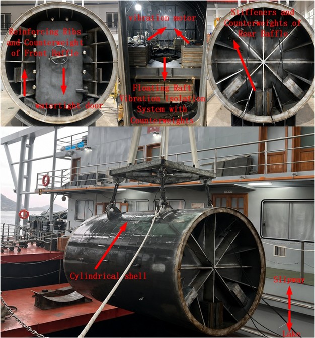
The primary test article for this study was a scaled cylindrical shell section designed to simulate the typical vibro-acoustic characteristics of a submarine pressure hull and its internal isolation system. Fig. 1 presents annotated photographs of the cylindrical shell model and the internal FRI system. The model comprised the following key components:
Cylindrical Shell Main Body: Fabricated from 8-mm-thick low-carbon steel, the cylindrical shell model had a total length of 3 m and a diameter of 2 m, with an effective cabin section length of 2 m. Five equally spaced circumferential stiffening rings (frames) were welded to the inner wall to replicate the stiffened structure of a real hull, enhancing its stiffness and influencing its modal properties.
Internal Floating Raft Isolation (FRI) System: This constituted the core subsystem. A rigid raft frame, constructed from welded steel sections, was supported via eight identical rubber isolators on four 'F'-shaped steel brackets connected to the inner shell wall. The eight isolators were symmetrically arranged to ensure balanced loading of the raft. Two independent variable-frequency three-phase vibration motors (labeled #1 and #2) were mounted on the top surface of the raft, serving as controlled internal excitation sources. The excitation sources used in the experiment were two YZS-20-2 variable-frequency three-phase asynchronous vibration motors. According to the manufacturer's specifications, each motor has a rated excitation force of 20 kN, a rated power of 1.5 kW, a rated current of 4.5 A, a rated rotational speed of 2870 r/min, and a mass of 150 kg. The two vibration motors were installed on the upper surface of the raft frame and used as independent internal excitation sources. Mechanically, the motors were rigidly connected to the raft frame through bolted connections, so that the excitation force generated by the rotating eccentric masses could be directly transmitted into the raft system. Electrically, each motor was driven by a standard industrial frequency inverter matched to the power and current ratings of the YZS-20-2 motor. The output frequency was set directly through the inverter, and the excitation frequency was controlled by adjusting the motor rotational speed to the prescribed operating conditions. Therefore, the frequency inverter was used only for electrical speed regulation and did not participate in the mechanical force-transmission path. The excitation force under each operating condition was determined according to the eccentric-mass setting and the operating rotational speed of the motor. Since the excitation force of a vibration motor is proportional to the square of the rotational speed, the actual excitation force in each test condition was lower than or different from the rated excitation force when the motor operated away from the rated rotational speed. This configuration enabled controlled single-source and dual-source excitation of the internal floating raft isolation system under the prescribed test frequencies.
End Closures: The cylinder was sealed at both ends by thick, removable steel end plates (forward and aft bulkheads), attached via flanges and bolts with rubber gaskets to ensure watertight integrity. Waterproof electrical penetrators were installed on the end plates for routing sensor cables.
The model design balanced considerations of structural dynamic similitude, laboratory spatial constraints, feasibility of sensor instrumentation, and waterproofing requirements.
Fig. 1Annotated photographs of the cylindrical pressure-cabin model and the internal FRI system, indicating the cylindrical shell, stiffening ribs/end plate, raft-mounted vibration motors, rubber isolators, and the location of the FRI subsystem. Photos by the authors at the Xin’anjiang Reservoir test site, Qiandao Lake, Zhejiang, China, in May 2024
2.2. Sensor configuration and data acquisition system
A dense sensor network was deployed to capture the complete physical chain from excitation source, through transmission paths, to the radiated sound field.
Group A (Source Monitoring): One triaxial piezoelectric accelerometer (sensitivity ≈100 mV/g) was installed at each of the two mounting feet of each vibration motor, totaling 4 measurement points (A1-1, A1-2, A2-1, A2-2), for direct measurement of the input excitation force characteristics.
Group B (Isolation Path Measurement): One triaxial piezoelectric accelerometer was installed on the upper side (raft side) and lower side (foundation side) of each isolator, totaling 16 points (B1-1 to B8-2). This group was critical for assessing the insertion loss (vibration level difference) of each isolator.
Group C (Shell Vibration Field Mapping): Nine uniaxial piezoelectric accelerometers (sensitivity ≈10 mV/g) were uniformly distributed circumferentially on the inner shell wall between the five stiffening rings. The measurement direction was radial (normal to the shell surface). Five rings resulted in a total of 45 points (C1-1 to C5-9), used to map the shell surface vibration velocity/acceleration distribution, identify hot spots, and observe modal participation.
Group D (Reference Measurement): One uniaxial accelerometer (D0) was installed at the same physical position as C1-1, occupying one channel and providing an additional reference response. Overall, Groups A-D comprised 66 measurement points and 106 acceleration channels: 4 triaxial points (12 channels) in Group A, 16 triaxial points (48 channels) in Group B, 45 uniaxial points (45 channels) in Group C, and 1 uniaxial point (1 channel) in Group D.
All acceleration signals were conditioned and digitized by two synchronized NI PXIe data acquisition systems. A synchronous sampling rate of 16.384 kHz was used, satisfying the Nyquist criterion for the highest analysis frequency (10 kHz) with sufficient margin.
Fig. 2Schematic sensor layout for the structural source-path-response measurement chain, showing the source-monitoring sensors, isolator-path sensors, shell-vibration-field sensors, and raft reference point
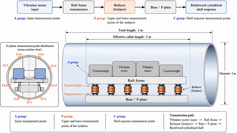
For Group C, C1-C5 denote five axial shell measurement rings from the forward end to the aft end, and Cj-1 to Cj-9 denote the nine circumferential points on the -th axial ring. For each axial ring, the circumferential numbering starts from the bottom position and proceeds counterclockwise when viewed from the forward end, with adjacent points separated by 40 degrees. This numbering rule allows each radial accelerometer to be traced relative to the adjacent stiffening rings and isolator-foundation connection regions.
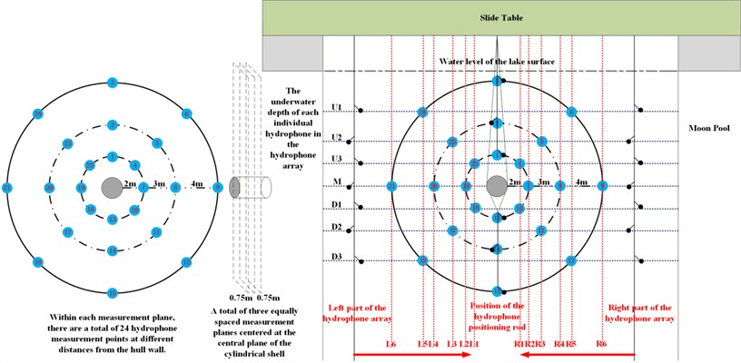
Hydroacoustic Measurement Array: Underwater acoustic radiation measurements were conducted at the Xin’anjiang Reservoir test site, Qiandao Lake, Zhejiang, China. The model was suspended horizontally within the designated measurement area. An array of 24 broadband spherical hydrophones (sensitivity –205 dB re 1 V/μPa) was fixedly deployed around the model as shown in Fig. 3. The array was divided into three sub-arrays positioned axially at the model’s “Forward”, “Midship”, and “Aft” sections, with 8 hydrophones in each sub-array covering various azimuthal angles in the horizontal plane. The hydrophones were positioned approximately 2 m from the shell surface, providing a consistent spatial sampling distance for comparison of the spectral and spatial radiation characteristics among the three sub-arrays. Hydrophone signals, after pre-amplification, were recorded by another synchronized NI PXIe system.
Synchronization and Triggering: The vibration and acoustic acquisition systems were strictly synchronized via shared 10 MHz clock and trigger signals, ensuring temporal alignment of all data for subsequent transfer path analysis and vibro-acoustic contribution st.
Fig. 3Hydroacoustic measurement array
2.3. Test conditions and procedure
The experiment was conducted in two main phases: in-air (“dry”) testing and underwater (“wet”) testing. Each phase followed the same sequence of excitation conditions.
Experimental Modal Analysis (EMA): Prior to installing the vibration motors, a roving impact hammer test with a force sensor was performed on the unloaded cylindrical shell. Frequency Response Functions (FRFs) were measured and processed using B&K PULSE Reflex software to identify the in-air natural frequencies, damping ratios, and mode shapes of the structure.
Background Noise Measurement: Before each operational test, data from all sensors were recorded for at least 60 seconds with no excitation (motors off) to establish the ambient background noise level, which was considered for subtraction in subsequent data processing.
Steady-State Operational Testing: The following three predefined operational conditions were executed sequentially. For each condition, the motors were run until steady-state operation was achieved (typically more than 30 seconds):
Condition 1 (Single Source, Low Frequency): Only Motor #1 was activated, driven by its inverter with a 25 Hz sinusoidal output.
Condition 2 (Single Source, Higher Frequency): Only Motor #2 was activated, driven by its inverter with a 40 Hz sinusoidal output.
Condition 3 (Dual Source, Combined Excitation): Both Motor #1 (25 Hz) and Motor #2 (40 Hz) were activated simultaneously.
For each condition, all vibration and acoustic data were synchronously acquired for a duration of 120 seconds. Each test was repeated three times to assess repeatability.
Notes on Underwater Testing: After being lowered into the designated underwater test area, the model was thoroughly vented and allowed to settle to stabilize the underwater environment. During underwater testing, one accelerometer located at the bottommost position on the shell (C5-1) failed due to a waterproofing breach. Its data were subsequently considered invalid and excluded from analysis – a common challenge in complex underwater experiments.
The failed C5-1 channel was used only for local shell-vibration-field mapping and was not involved in the calculation of isolator insertion loss based on Group B sensors or in the calculation of hydrophone-array sound pressure levels. Therefore, excluding this channel affected only the local completeness of the shell-vibration map near this position and did not change the main isolation and acoustic-radiation conclusions. No interpolation was used for the failed channel.
2.4. Data processing methodology
Vibration Data: Acceleration time histories were windowed (Hanning window) and transformed to the frequency domain via Fast Fourier Transform (FFT). The Vibration Acceleration Level (VAL) was computed as: , where is the acceleration spectral amplitude (m/s2) and 1×10⁻⁶ m/s2.
The Vibration Level Difference (or Insertion Loss, IL) for an isolator was defined as the difference in VAL between its upper and lower measurement points: .
To assess broadband performance, the Overall Vibration Level was calculated for three frequency ranges: 5-315 Hz (low-frequency band), 315 Hz-10 kHz (mid-to-high-frequency band), and the full band from 5 Hz-10 kHz.
Acoustic Data: Hydrophone voltage signals were converted to sound pressure using individual calibration factors. The Sound Pressure Level (SPL) was computed as: , where is the sound pressure spectral amplitude (Pa) and 1×10⁻⁶ Pa.
Spectral and Sonogram Analysis: Narrowband spectra (high-resolution FFT) were used to analyze tonal components and fine spectral structure. Concurrently, one-third octave band spectra were employed to evaluate the distribution of broadband noise energy across standard frequency bands, a common practice in engineering acoustics.
Data Validation: The validity and reliability of the data were ensured by comparing results from repeated tests, examining coherence functions, and verifying that the spectral content at the source measurement points (Group A) corresponded with the drive signal frequencies.
In the repeated operational tests, frequency stability was first checked at the source-monitoring points. Invalid channels were excluded before any spatial averaging, and the number of valid channels used in each averaged quantity was kept consistent within each comparison.
3. Results
3.1. Structural modal characteristics
Experimental Modal Analysis (EMA) conducted in air successfully identified the dominant modes of the cylindrical shell structure below 200 Hz. Table 1. summarizes the parameters of the first four significant modes. The first global mode occurred at 128.3 Hz, characterized as a "breathing" mode (axisymmetric radial deformation) of the shell, as shown in Fig. 4.
Fig. 4Mode shape of the first breathing mode at 128.3 Hz and shape of the second ovaling mode at 145.5 Hz
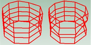
The second mode (145.5 Hz) exhibited an “oval” cross-sectional deformation ( 2). Both these frequencies are significantly higher than the highest fundamental frequency used to excite the vibration motors (40 Hz) and its significant low-order harmonics (e.g., 80 Hz, 120 Hz). This implies that global structural resonance was avoided during the operational conditions investigated in this study, thereby precluding potential amplification of vibration transmission and acoustic radiation due to resonance. The observed phenomena are thus primarily attributable to the intrinsic dynamic properties of the isolation system and the forced vibration response. Higher-order local modes (e.g., shell panel vibrations) were identified at frequencies above 200 Hz.
Table 1Key results from experimental modal analysis (in air) of the cylindrical shell
Mode Order | Frequency (Hz) | Primary mode shape description |
1 | 128.3 | Axisymmetric radial “breathing” mode |
2 | 145.5 | Ovaling cross-sectional deformation ( 2) |
3 | 172.0 | Three-lobed cross-sectional deformation ( 3) |
4 | 198.5 | Complex deformation with axial-circumferential coupling |
3.2. Isolation system performance: vibration level difference analysis
The core performance metric of the isolation system – the Vibration Level Difference (IL), or Insertion Loss – was calculated from data acquired by Group B sensors (upper and lower sides of each isolator). Table 2. summarizes the overall vibration levels and corresponding IL for all eight isolators across three analysis frequency bands during the representative underwater Condition 1 (25 Hz excitation).
Table 2Overall Vibration Acceleration Level (VAL) and Vibration Level Difference (IL) for the eight isolators during underwater Condition 1 (25 Hz excitation), presented as three frequency-band sub-tables
5-315 Hz band | |||
Isolator No. | VAL_Up (dB) | VAL_Low (dB) | IL (dB) |
1 | 134.07 | 106.67 | 27.40 |
2 | 131.08 | 102.28 | 28.80 |
3 | 125.20 | 105.74 | 19.46 |
4 | 123.23 | 101.80 | 21.43 |
5 | 125.41 | 107.87 | 17.54 |
6 | 120.36 | 95.09 | 25.27 |
7 | 129.28 | 108.72 | 20.56 |
8 | 132.77 | 105.47 | 27.30 |
315 Hz-10 kHz band | |||
Isolator No. | VAL_Up (dB) | VAL_Low (dB) | IL (dB) |
1 | 118.07 | 95.44 | 22.63 |
2 | 119.67 | 97.24 | 22.43 |
3 | 126.50 | 96.33 | 30.17 |
4 | 122.76 | 90.81 | 31.95 |
5 | 110.84 | 86.01 | 24.83 |
6 | 104.82 | 87.96 | 16.86 |
7 | 114.69 | 89.37 | 25.32 |
8 | 108.45 | 84.60 | 23.85 |
5 Hz-10 kHz full band | |||
Isolator No. | VAL_Up (dB) | VAL_Low (dB) | IL (dB) |
1 | 134.18 | 106.99 | 27.19 |
2 | 131.38 | 103.46 | 27.92 |
3 | 128.91 | 106.21 | 22.70 |
4 | 126.01 | 102.13 | 23.88 |
5 | 125.56 | 107.90 | 17.66 |
6 | 120.48 | 95.86 | 24.62 |
7 | 129.43 | 108.77 | 20.66 |
8 | 132.79 | 105.50 | 27.29 |
Several key conclusions can be drawn from Table 2. First, across the 5 Hz-10 kHz full band, the IL for all isolators ranged from 17.5 dB to 27.9 dB, with a mean value of 23.9 dB. This demonstrates substantial broadband isolation by the FRI system in the underwater environment. Second, there is some variation in performance among individual isolators (standard deviation approximately 3.5 dB), likely due to manufacturing tolerances, slight differences in installation preload, or asymmetries in local boundary conditions – a reflection of typical real-world engineering scenarios. Third, comparing different frequency bands, the mean IL in the mid-to-high frequency band (315 Hz-10 kHz) was slightly higher at 24.6 dB than that in the low-frequency band (5-315 Hz) at 23.5 dB, which is generally consistent with the stiffness characteristics of the isolators and the mass distribution of the system.
Fig. 5Narrowband vibration acceleration level spectra from the 18 measurement channels used for isolator/path evaluation under Condition 1 (Motor #1, 25 Hz, first repeated test). The curves compare in-air and underwater responses and are used to evaluate whether fluid loading changes the isolator transmission characteristics
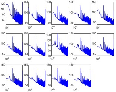
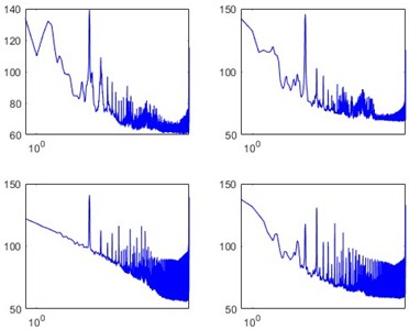
Fig. 5 shows that the results from both environments are remarkably close, differing by less than within approximately 2 dB. Statistics across all eight isolators indicate that the mean absolute difference between in-air and underwater IL is less than 1.5 dB. This suggests that, for the mid-to-high frequency vibration of interest in this study, the fluid loading (added mass and radiation damping) did not significantly affect the force transmission characteristics of the isolators themselves, demonstrating good environmental robustness of their isolation performance.
3.3. Underwater radiated noise characteristics
Measurements from the hydrophone array revealed the model's underwater acoustic radiation signature. Fig. 6 presents the narrowband SPL spectra recorded under Condition 2 (Motor #2, 40 Hz, first repeated test), which are used to identify the dominant excitation tonal and harmonic components.
The most prominent feature in the spectrum is the extremely high tonal peak at 40 Hz, with an SPL reaching approximately 152 dB re 1 μPa. Its second (80 Hz) and third (120 Hz) harmonics are also clearly visible, albeit with SPLs decreasing by about 15-20 dB each. Apart from these discrete lines directly related to the excitation, the background broadband noise level is relatively flat in the 50-500 Hz range, around 110-120 dB, as shown in Fig. 6.
This representation more clearly illustrates the distribution of broadband acoustic energy under different excitations:
– Condition 1 (25 Hz): A peak appears in the 31.5 Hz center band (encompassing the 25 Hz line). Above 125 Hz, the SPL stabilizes, forming a noise “floor” or plateau.
– Condition 2 (40 Hz): The highest peak appears in the 40 Hz center band. The level of its noise plateau is elevated overall compared to Condition 1.
– Condition 3 (Dual Source): Peaks appear in both the 31.5 Hz and 40 Hz bands. Notably, the SPL of its high-frequency (above 200 Hz) noise plateau is not significantly higher than that of Condition 2, and is even slightly lower in some bands.
To quantify the change in overall radiated sound level, the average SPL in the 5 Hz–10 kHz band was calculated across all hydrophones in the “Forward”, “Midship”, and “Aft” sub-arrays. The results are presented in Table 3. From Condition 1 to Condition 2, the total radiated sound level increased by approximately 9-10 dB, aligning with the change in excitation source strength (motor speed/excitation force). However, from Condition 2 to Condition 3, the increase in total radiated level was limited to about 0.5-1 dB, indicating that the 40 Hz source dominated the overall level and that the dual-source response should be interpreted through energy-level imbalance and source-path coupling rather than simple equal-source superposition.
Fig. 6Narrowband underwater sound pressure level spectra recorded by the hydrophone array under Condition 2 (Motor #2, 40 Hz, first repeated test). The curves correspond to valid hydrophone-array channels distributed in the forward, midship, and aft sub-arrays rather than to one-to-one structural measurement points, and they show the dominant 40 Hz tonal component and its harmonics
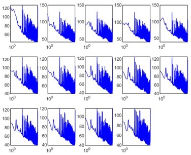
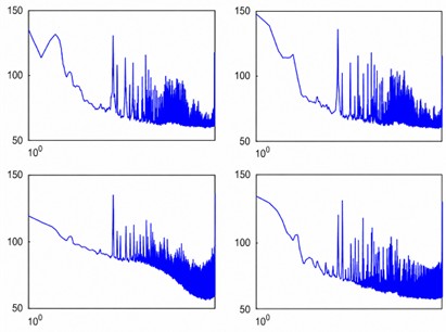
Fig. 7One-third-octave-band spectra (center frequencies from 25 Hz to 10 kHz) for representative hydrophone channels under the three operational conditions
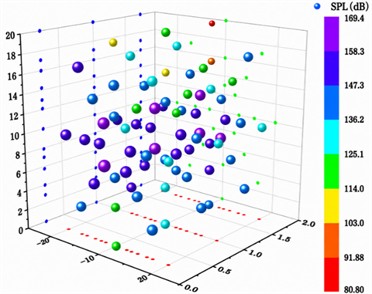
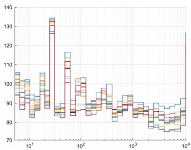
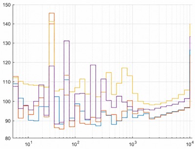
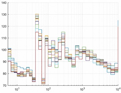
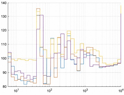
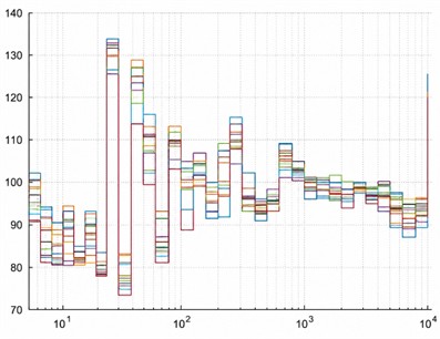
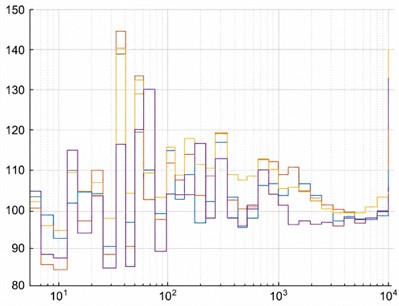
Table 3Average Sound Pressure Level (5 Hz-10 kHz) for each hydrophone sub-array under different operational conditions
Condition | Forward Array Avg. SPL (dB) | Midship Array Avg. SPL (dB) | Aft Array Avg. SPL (dB) |
Condition 1 (L25Hz) | 139.8 | 142.1 | 140.5 |
Condition 2 (R40Hz) | 149.3 | 151.7 | 149.9 |
Condition 3(L25Hz + R40Hz) | 149.9 | 152.2 | 150.4 |
4. Discussion
4.1. Effectiveness and environmental robustness of the isolation performance
The experimental results first and foremost validate the core value of the FRI system in suppressing structure-borne sound transmission. The mean full-band insertion loss of 23.9 dB in the 5 Hz-10 kHz band (Table 2.) corresponds to an acceleration-amplitude ratio of approximately 0.064 between the lower and upper isolator measurement positions, indicating substantial attenuation along the vibration-transmission path and providing a solid basis for reducing underwater broadband radiated noise. It is particularly noteworthy that the performance variation among different isolators (standard deviation of approximately 3-4 dB) reflects the randomness in manufacturing and installation, suggesting that pre-screening and matched installation of isolators could help optimize the consistency of overall system performance in practical engineering.
Regarding the impact of the fluid environment, this experiment yields an important conclusion: for the frequency band of interest in this study (5 Hz-10 kHz), the in-air and underwater insertion-loss results remained close, with a mean absolute difference of less than 1.5 dB (Fig. 5), indicating no systematic or practically meaningful degradation of the measured isolation performance after submergence. This finding contrasts with some intuitive concerns that fluid loading might degrade isolation performance. A plausible explanation is that in the mid-to-high frequency range, the dynamic stiffness and damping of the isolators themselves are the dominant factors controlling force transmission, while the change in the overall inertial properties of the system due to fluid-added mass is relatively minor in this band [15, 16]. Furthermore, while the radiation damping introduced by the fluid increases the system's energy dissipation, its primary effect is on the shell in direct contact with the fluid, and its influence on the internal, elastically isolated raft-isolator subsystem is indirect and weak. This characteristic of environmental robustness has positive implications for simplifying the design evaluation process – key isolation performance can, in some cases, be preliminarily validated through more easily conducted “dry” tests.
4.2. Dominance of tonal radiation and the “source-path-receiver” linkage
The most prominent feature of the radiated noise measurements (Fig. 6 and Fig. 7) is the extremely high tonal components at the excitation frequencies. Despite the effective suppression of broadband vibration transmission by the isolation system, the 25 Hz and 40 Hz tonals still overwhelmingly dominate the radiated sound field, with SPLs 30-40 dB higher than the broadband noise floor. This phenomenon profoundly reveals the nature of the “source-path-receiver” chain: the isolation system acts as an efficient high-pass filter, providing significant attenuation for broadband noise well above its mounting frequency; however, for low-frequency discrete components with frequencies close to or below the mounting frequency and high amplitude, the isolator’s effectiveness is limited (partly reflected by the slightly lower IL in the 5-315 Hz band in Table 2). The residual synchronous shell vibration is sufficient to excite strong acoustic radiation. This serves as a critical warning that relying solely on advanced transmission path control technologies (like FRI) is insufficient to address all noise issues. Source treatment of the low-frequency tonal characteristics of the excitation sources themselves is imperative, such as improving the dynamic balance of rotating components, employing stepless speed control, or using active control techniques to avoid or mitigate these strong discrete components. In the dual-source condition (Condition 3) of this experiment, the two tonals remained distinctly identifiable and did not merge, further underscoring the importance of managing multiple discrete sources independently.
4.3. Limited overall-level increase under dual-source excitation
A key observation is that the total radiated level under dual-source excitation (Condition 3) increased only slightly compared with Condition 2 (Table 3.). This result should not be interpreted directly against the 3 dB rule for two equal, incoherent sources. The measured total levels show that Condition 2 was already about 9-10 dB higher than Condition 1. When a weaker source is added energetically to a stronger source, the theoretical increase of the total level is small; for a 9-10 dB level difference, it is approximately 0.4-0.5 dB, which is close to the observed 0.5-1 dB. Thus, the limited increase is consistent with the dominance of the 40 Hz source.
Any residual difference between the simple energetic estimate and the measured 0.5-1 dB increase may arise from spatial averaging across hydrophone positions, test repeatability, and the frequency-dependent transfer and radiation characteristics of the raft-shell-water system. Because the two motors operate at different frequencies, coherent interference between the two sources is not expected at a single frequency. At each tonal frequency, however, the phase relation between the local excitation and its structural transfer path affects the spatial distribution of shell vibration, while structural modal participation and local acoustic-radiation efficiency govern conversion into radiated sound. These mechanisms support evaluating multi-source underwater radiation within a coupled source-path-receiver framework rather than by applying the equal-source 3 dB rule directly.
4.4. Preliminary observations on shell vibration distribution and radiation efficiency
Although detailed shell vibration contour maps are not elaborated here, preliminary data from Group C sensors indicate that under FRI, shell vibration is not uniformly distributed. Vibrational energy is primarily concentrated in shell areas corresponding to the connection points of the isolator foundations and certain inter-frame regions, showing obvious localized, “patchy” characteristics rather than whole-body modal vibration. The acoustic radiation efficiency of this “patch” vibration, driven by discrete transmission paths, may differ from that of global modal radiation. This is an important direction for future research focusing on the acoustic radiation characteristics of shells.
4.5. Experimental limitations and future work
This study has several limitations, which also point to directions for future research:
Frequency Range: The upper analysis limit was 10 kHz, while frequencies of practical engineering concern may be higher. Future work needs to extend the testing and analysis band to higher frequencies to study isolator performance in the high-frequency domain (e.g., stiffness effects) and the radiation characteristics of high-frequency shell vibrations.
Excitation Type: Only steady-state sinusoidal excitation was used. Actual machinery noise comprises start-up, speed variation, broadband impacts, etc. Future studies should introduce more realistic excitation spectra, such as broadband random or transient impact excitation, to examine the dynamic response and acoustic radiation characteristics of the isolation system.
Model Complexity: The current model is a single bay. Actual hulls are multi-bay coupled structures where bulkheads and piping systems influence vibration transmission and acoustic radiation. Developing a multi-bay coupled experimental model is a crucial step toward closer engineering relevance.
Numerical Model Validation: The comprehensive dataset generated in this study is a valuable resource for validating high-fidelity fluid-structure interaction vibro-acoustic numerical models. A core task for the future is to compare and calibrate the predictions of models such as Finite Element/Boundary Element (FEM/BEM) or Statistical Energy Analysis (SEA) against the experimental results presented here.
5. Conclusions
This study experimentally investigates the vibro-acoustic performance of a cylindrical shell with a floating raft isolation (FRI) system in air and underwater environments. Key findings are: (1) The FRI system provides substantial broadband isolation underwater, with a mean full-band insertion loss of 23.9 dB and a mean absolute air-underwater insertion-loss difference below 1.5 dB, supporting preliminary evaluation via land-based tests; (2) Radiated noise is dominated by low-frequency excitation tonal components, where FRI has limited effectiveness, necessitating a combined source-and-path noise control strategy; (3) Under dual-source excitation, the stronger 40 Hz source dominated the overall radiated level, and adding the 25 Hz source increased the measured overall level by only about 0.5-1 dB relative to Condition 2; (4) The structural design avoids operational resonance, ensuring reliable performance characterization of the isolation system. This work provides benchmark experimental data for FRI underwater vibro-acoustic research, with direct implications for underwater vehicle low-noise design. Future work will address the limitations of frequency band, excitation form and model complexity, and calibrate high-fidelity numerical models with the data. Overall, the same integrated cylindrical shell-FRI system was evaluated in both air and underwater environments, so the environmental robustness of the isolation path and the source-dominated nature of underwater radiated noise were identified experimentally rather than inferred only from numerical simulation or dry tests.
References
-
D. Ross, Mechanics of Underwater Noise. Oxford, U.K.: Pergamon Press, 1976.
-
T. A. Smith and J. Rigby, “Underwater radiated noise from marine vessels: a review of noise reduction methods and technology,” Ocean Engineering, Vol. 266, p. 112863, Oct. 2022, https://doi.org/10.1016/j.oceaneng.2022.112863
-
S. J. Elliott, “Active control of structure-borne noise,” Journal of Sound and Vibration, Vol. 177, No. 5, pp. 651–673, Oct. 2002, https://doi.org/10.1006/jsvi.1994.1459
-
J. Niu, K. Song, and C. W. Lim, “On active vibration isolation of floating raft system,” Journal of Sound and Vibration, Vol. 285, No. 1-2, pp. 391–406, Dec. 2004, https://doi.org/10.1016/j.jsv.2004.08.013
-
J. C. Snowdon, “Vibration isolation: use and characterization,” Rubber Chemistry and Technology, Vol. 53, No. 5, pp. 1041–1087, Feb. 2011, https://doi.org/10.5254/1.3535079
-
B. Yang, Y. Hu, F. Vicario, J. Zhang, and C. Song, “Improvements of magnetic suspension active vibration isolation for floating raft system,” International Journal of Applied Electromagnetics and Mechanics, Vol. 53, No. 2, pp. 193–209, May 2017, https://doi.org/10.3233/jae-150167
-
L. Yingli and X. Daolin, “Force transmissibility of floating raft systems with quasi-zero-stiffness isolators,” Journal of Vibration and Control, Vol. 24, No. 16, pp. 3608–3616, May 2017, https://doi.org/10.1177/1077546317708460
-
D. F. Ledezma Ramirez, P. E. Tapia Gonzalez, M. Castillo Morales, T. P. Berber Solano, and A. Salas Zamarripa, “Shock response of a two-stage vibration isolation system,” Ingeniería Investigación Y Tecnología, Vol. 21, No. 2, pp. 1–11, 2020, https://doi.org/10.22201/fi.25940732e.2020.21n2.018
-
X. C. Huang et al., “Design sensitivity analysis and optimization of a floating raft system using a FRF-based substructuring method,” Journal of Vibration and Shock, Vol. 30, No. 5, pp. 145–151, 2011.
-
Q. Xue et al., “Experimental and simulation study on vibration transmission characteristics and vibration isolation effect of a new floating raft vibration isolation system,” Journal of Marine Science and Engineering, Vol. 13, No. 2, p. 254, Jan. 2025, https://doi.org/10.3390/jmse13020254
-
Z. Lei, C. Wu, Y. Liu, Z. Chen, and J. Su, “Vibration and sound radiation analysis of floating raft and hull coupling system based on generalized variational principle,” (in Chinese), Chinese Journal of Ship Research, Vol. 20, No. 5, pp. 46–57, 2025, https://doi.org/10.19693/j.issn.1673-3185.04249
-
J. Zhang, D.-L. Xu, Y.-L. Li, and J.-X. Zhou, “Line spectrum chaotification of a double-layer vibration isolation floating raft system under multi-source excitation,” Acta Physica Sinica, Vol. 63, No. 18, p. 180505, Dec. 2020, https://doi.org/10.7498/aps.63.180505
-
X. Wang, H. Lin, Y. Zhu, and W. Wu, “Vibro-acoustic modelling of immersed cylindrical shells with variable thickness,” International Journal of Naval Architecture and Ocean Engineering, Vol. 12, pp. 343–353, Dec. 2019, https://doi.org/10.1016/j.ijnaoe.2019.12.003
-
S. Liu, R. Huo, and L. Wang, “Vibroacoustic transfer characteristics of underwater cylindrical shells containing complex internal elastic coupled systems,” Applied Sciences, Vol. 13, No. 6, p. 3994, Mar. 2023, https://doi.org/10.3390/app13063994
-
B. Laulagnet and J. L. Guyader, “Modal analysis of a shell’s acoustic radiation in light and heavy fluids,” Journal of Sound and Vibration, Vol. 131, No. 3, pp. 397–415, 1989, https://doi.org/10.1016/0022-460x(89)91001-8
-
M. Caresta and N. J. Kessissoglou, “Structural and acoustic responses of a fluid-loaded cylindrical hull with structural discontinuities,” Applied Acoustics, Vol. 70, No. 7, pp. 954–963, Jan. 2009, https://doi.org/10.1016/j.apacoust.2008.11.004
-
E. A. Skelton and J. H. James, Theoretical acoustics of underwater structures. London, U.K.: Imperial College Press, 2011, https://doi.org/10.1142/9781848160750
-
M. C. Junger, “Vibrations of elastic shells in a fluid medium and the associated radiation of sound,” Journal of Applied Mechanics, Vol. 19, No. 4, pp. 439–445, Dec. 1952, https://doi.org/10.1115/1.4010540
-
K. Zhao, J. Fan, B. Wang, and W. Tang, “Vibroacoustic behavior of a partially immersed cylindrical shell under point-force excitation: analysis and experiment,” Applied Acoustics, Vol. 161, p. 107170, Dec. 2019, https://doi.org/10.1016/j.apacoust.2019.107170
-
B. E. Sandman and A. Harari, “Triaxial acoustical characteristics of submerged cylindrical shells,” The Journal of the Acoustical Society of America, Vol. 87, No. S1, pp. S49–S49, 1990, https://doi.org/10.1121/1.2028247
-
A. A. Jafari and M. Bagheri, “Free vibration of rotating ring stiffened cylindrical shells with non-uniform stiffener distribution,” Journal of Sound and Vibration, Vol. 296, No. 1-2, pp. 353–367, 2006, https://doi.org/10.1016/j.jsv.2006.03.001
About this article

This work was supported by the China National Nuclear Corporation (CNNC) Leading Innovation Research Project (Grant No. CNNC-LCKY-202254).
The datasets generated during and/or analyzed during the current study are available from the corresponding author on reasonable request.
Quansheng Hu: conceptualization, methodology, writing- original draft. Yilei Li: formal analysis, supervision. Chaoying Wang: funding acquisition, investigation. Qichao Xue: project administration, writing-review and editing, visualization. Guangping Zou: resources. Mingtao Chen: software.
The authors declare that they have no conflict of interest.

