Abstract
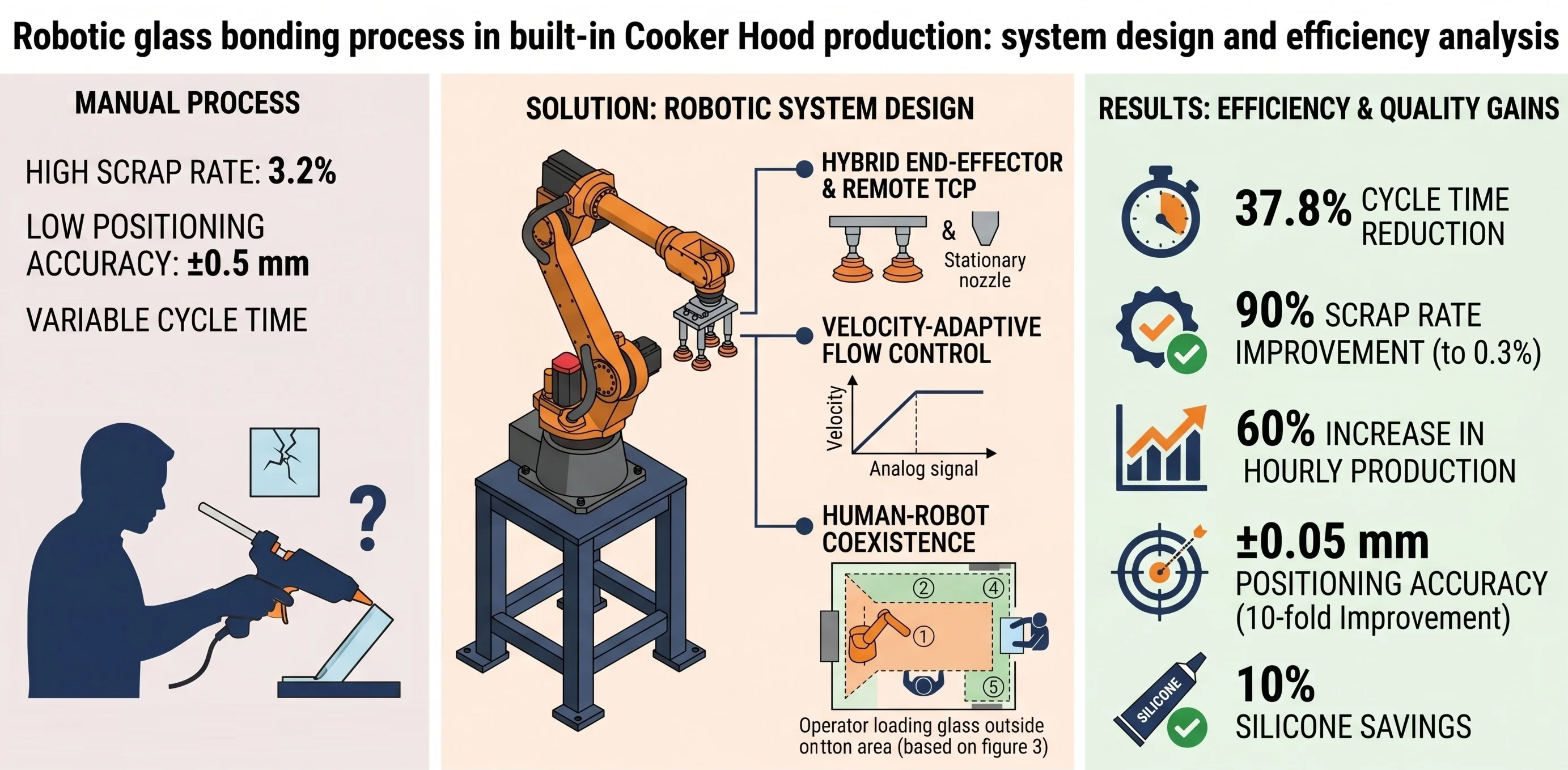
In the home appliances industry, shifting consumer expectations toward aesthetic and modern designs have led to the widespread use of glass materials instead of metal. However, the brittle nature of glass renders traditional mechanical fastening methods (screws or rivets) inadequate; stress concentrations formed on the material threaten structural integrity. Consequently, the industry has turned to adhesive bonding technologies that optimize load distribution. Nevertheless, in manual adhesive application processes, operator-induced physiological tremors and velocity fluctuations degrade sealing quality and result in high scrap rates. This study examines the conversion of the manual glass bonding process in built-in cooker hood production into a semi-automated assembly cell through the integration of a six-axis industrial robot (FANUC M-710iC/70). Within the scope of this research, a hybrid end-effector combining vacuum pads, and a dispenser was designed, and Remote TCP (stationary nozzle, moving part) trajectory planning was implemented to prevent silicone accumulation. Additionally, a human-robot coexistence model was developed, enabling humans and robots to safely share the same workspace. Experimental results demonstrate that robotic automation reduced the cycle time by 37.8 %, increased hourly production capacity by 60 %, and improved the scrap rate by 90 % (from 3.2 % to 0.3 %) compared to the manual process, while achieving a 10 % reduction in silicone consumption and a 10-fold improvement in positioning accuracy. The developed system ensured quality standardization in high-viscosity silicone application and minimized ergonomic risks.
Highlights
- A semi-automated robotic cell featuring human-robot coexistence decreased the glass bonding scrap rate by 90%.
- A hybrid end-effector and Remote TCP architecture prevented silicone accumulation.
- Robotic automation reduced the cycle time by 37.8% and increased capacity by 60%.
- The system achieved a 10-fold improvement, reaching ±0.05 mm positioning accuracy.
- Flow control algorithms standardized application and reduced silicone use by 10%.
1. Introduction
In the Industry 4.0 era, manufacturing sectors are redefining production processes in response to intensifying global competition and evolving consumer expectations. With the widespread adoption of smart factories and mechatronic systems, automation technologies have evolved from mere tools for enhancing production speed into strategic assets that ensure quality standardization, minimize human error, and augment flexible manufacturing capabilities. Particularly in sectors with high production volumes, such as home appliances, the inherent variability of manual assembly operations imposes significant constraints on efficiency and quality.
In recent years, the home appliances industry has undergone a major design transformation driven by technological advancements and the pursuit of aesthetic appeal and functional utility. Increasing consumer demand for modern, sleek, and energy-efficient appliances has prompted manufacturers to transition from traditional metal surfaces to glass materials. Tempered and decorative glass have become dominant materials in the design of appliances such as built-in cooker hoods, hobs, and ovens [1]. However, the integration of glass into production processes has introduced new engineering challenges to assembly lines.
The use of traditional mechanical joining methods – such as screws, rivets, or bolts – for mounting glass onto metal bodies poses serious risks due to the brittle nature of the material [2]. Drilling holes and applying localized point forces on the glass surface create stress concentrations that can lead to fractures and the loss of structural integrity [3]. Consequently, adhesive bonding technologies, which distribute loads evenly across the interface, accommodate materials with different thermal expansion coefficients, and preserve part integrity, are preferred as a more reliable alternative to mechanical fastening [2].
Nevertheless, the manual execution of industrial adhesive processes is unsustainable from the perspective of quality consistency. Fluctuations in adhesive viscosity due to ambient temperature, combined with operator-induced physiological tremors, cause deviations in the thickness and homogeneity of the adhesive bead [4]. Velocity fluctuations and positioning errors in manual application diminish sealing quality and increase scrap rates [5], [6]. In this context, robotic dispensing systems eliminate the limitations of manual labor through micron-level precision, constant speed control, and repeatable trajectory tracking capabilities [5], [7].
While existing literature extensively addresses robotic adhesive dispensing within the automotive sector [8]-[10] those applications typically rely on moving tool configurations governed by functional tolerances (±0.1 to 0.5 mm). In contrast, built-in appliance manufacturing demands strict aesthetic perfection and involves handling large, flat, and highly brittle glass surfaces. The novelty of this study lies in the implementation of a velocity-adaptive Remote TCP (Moving Part) architecture that overcomes the severe inertia constraints of conventional dispensing. By utilizing rapid robotic wrist rotations instead of linear inter-machine movements, this study demonstrates a unique methodology to achieve simultaneous optimization of cycle time and an ultra-precise aesthetic tolerance of ±0.05 mm filling a critical gap in high-volume home appliance automation.
This study presents a case analysis examining the transition from manual processes to robotic automation in the glass adhesive application for built-in cooker hoods at a manufacturing facility operating within the home appliances sector.
2. System design and robot selection criteria
The automation of the glass adhesive application process in a built-in cooker hood production line requires an integrated system design that considers robot kinematics, end-effector design, and material flow dynamics. In this research, a robotic cell was developed with an architecture that combines industrial durability with high-precision dispensing capabilities. The FANUC M-710iC/70, a 6-axis industrial robot, was selected for the adhesive operation. This choice was driven by key parameters established in the literature for robotic adhesive systems: precision, payload capacity, and reach.
Payload Capacity and Inertia: In robotic dispensing systems, the stability of the mechanical arm plays a decisive role in quality; particularly, dynamic behaviors such as friction and hysteresis in the gearboxes of industrial robots designed for heavy loads limit trajectory accuracy [11]. Vibrations occurring during acceleration phases or multi-axis movements can lead to arm tremors due to acceleration values exceeding maximum limits or hardware capacity, resulting in quality losses. Furthermore, excessive joint fatigue and wear under high loads lead to mechanical backlash, negatively impacting the repeatability of the system [12]. The 70 kg payload capacity of the robot was selected not only to support the weight of the adhesive gun but also to withstand the dynamic loads and moments of inertia generated during the vacuum-assisted handling of glass panels during assembly.
Reach and Workspace: In robotic applications, it is a critical requirement for operational efficiency and safety that the robot can access all locations within the workspace and that no blind spots remain within the system's sensing capacity [13]. The 2050 mm reach of the robot is sufficient to accommodate the range of cooker hood glass sizes and the width of the adhesive fixture.
Positioning Accuracy: In bonding and sealing processes, micron-level precision plays a critical role in both reducing operational costs and maintaining structural integrity. Unlike dosing inconsistencies in manual methods, advanced automated systems minimize waste, processing time, and cleaning requirements by strictly controlling material usage [14]. Particularly in micro- or nano-liter applications, closed-loop intelligent control algorithms – which calculate the residual volume dripping after the valve closes and compensate for microscopic excesses in the subsequent cycle – ensure flawless dosing [15]. In joints requiring sealing and hybrid assembly methods, complete filling of the adhesive line is vital; however, high dispensing precision prevents material overflow, which could contaminate peripheral equipment or cause structural defects [4], [8]. A study emphasized that a positioning accuracy of 200 nm achieved through active robotic control strategies guarantees sealing quality by preventing capillary shrinkage and physical drifts that may occur during curing [5]. In this regard, the ±0.04 mm repeatability value offered by the robot is of critical importance.
2.1. End-effector and dispensing system
In robotic adhesive processes, the end-effector serves not only as the physical contact point of the system but also as the control center for the hydrodynamic parameters that determine process quality. Liquid dispensing in automation systems fundamentally relies on the complex relationship between fluid rheology, nozzle geometry, and applied pressure [15]. According to the theoretical framework established by [16] and [17], the volumetric flow rate () in automated dispensing systems is directly related to the applied pneumatic pressure (), the viscosity of the fluid (), and the internal diameter of the nozzle (). Although an increase in pressure linearly increases the flow rate under ideal conditions according to the Hagen-Poiseuille law, in thixotropic (fluids whose viscosity decreases under shear stress) and high-viscosity materials such as silicone, this relationship becomes non-linear, evolving into a process variable that is difficult to manage [18].
Such high-precision systems offer significant advantages compared to manual application, including micron-level repeatability and material consumption savings [15]. However, the sustainability of these advantages depends on overcoming fundamental challenges within the industrial environment. A primary challenge frequently highlighted in the literature is the instantaneous alteration of adhesive viscosity induced by ambient temperature fluctuations [8]. It is noted that even a slight decrease in temperature increases viscosity, thereby raising the flow resistance at the nozzle tip, which leads to thinning or interruptions in the bead profile [6], [8], [17]. Another critical challenge is the issue of dragging and accumulation [6]. If the dispensing rate remains constant while the robot decelerates during corner turns, silicone accumulation occurs at the corners; conversely, during sudden accelerations, the bead thins or breaks [7].
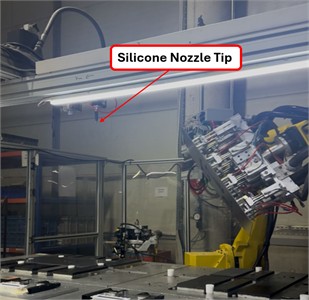
To manage these hydrodynamic and kinematic challenges, the control architecture of the system is structured around the concept of the Tool Center Point (TCP) [12], [13], [19]. The TCP is a virtual point at the very tip of the nozzle that defines the robot’s position, orientation, and velocity in space. In robotic trajectory planning, regardless of the joint velocities of the robot arm, the primary critical parameter is the tangential velocity of the TCP on the glass surface. For high-quality sealing, seamless synchronization is required between the TCP velocity () and the volumetric flow rate () of the silicone exiting the dispenser [7], [13]. The system utilizes a velocity-adaptive control loop that proportionally reduces the flow rate at corner points where decreases and increases it to maximum speed on straight lines. The structure of the hybrid end-effector designed in light of these theoretical and practical requirements is detailed in Fig. 1. The most prominent structural feature in the visual is the manner in which the dispensing nozzle and the handling system are integrated.
In robotic dispensing systems for applications such as bonding, having a stable mechanical structure is essential for ensuring flow precision as well as the safe handling of heavy and fragile loads under dynamic conditions [13]. The pneumatic nozzle seen in Fig. 1 is equipped with a high-precision valve system capable of regulating pressure against viscosity changes. Additionally, another innovative aspect of the design is the group of vacuum pads placed symmetrically around the nozzle. When the robot reaches high accelerations during PTP (Point-to-Point/Joint) movements to reduce production time, significant inertia forces are generated on the glass panel [11-13]. The multiple vacuum pad arrangement detailed in Fig. 1 prevents the glass from slipping or breaking under stress by spreading these forces over a large surface area.
Fig. 1Integrated 6-axis robot manipulator and end-effector structure. Photo by Altuğ Pirselimoğlu, Amasya, Türkiye, June 12, 2025
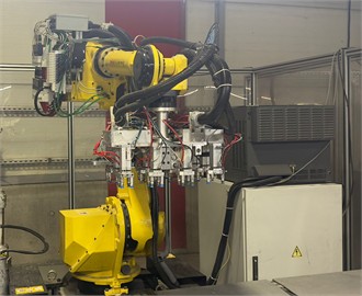
a) 6-axis robot
b) Positioning of vacuum pads
2.2. Motion control and programming architecture
The established system consists of a 6-axis FANUC M-710iC/70 industrial robot and a high-viscosity adhesive dispensing unit. The robot has a maximum linear speed of 2500 mm/s and a repeatability accuracy of ±0.03 mm [12]. In the system, a barrel pump with a pneumatic drive and a precision regulator that prevents pressure fluctuations are used for the continuous feeding of high-viscosity silicone (Shore A hardness: 25-30). To ensure that the 8.20 ml dosage remains constant in each cycle (45 s), the system pressure is managed via a proportional valve integrated with the robot controller. In this study, a kinematic approach defined in the literature as “Stationary Tool-Moving Part” was adopted. In this method, vacuum pads carrying the glass panel are integrated into the end-effector of the robot, while the silicone nozzle (Tool) is fixed at a stationary position in space. This configuration is based on the Remote TCP principle stated by [20], which specifically prevents hose twisting during the processing of large parts and increases trajectory precision.
Trajectory planning and motion control of the system are provided by a hybrid architecture running on the FANUC R-30iB Plus control unit. This architecture relies on the integration of signal processing algorithms managed by the Teach Pendant command set, which provides operational flexibility. Due to the nature of the bonding process, two different motion strategies (interpolation types) were devised with a focus on speed and precision.
PTP interpolation was used for air-cut movements, such as the robot’s approach to the operation area from the Home position, part transfer, and retraction to the safe zone after processing, where trajectory precision is not critical. In PTP motion, the robot controller calculates the shortest path between the start and end points not as a linear line in Cartesian space, but as a curve that the robot joint angles (J1-J6) will complete with the minimum energy and in the shortest time. In this type of motion, the robot's tip (TCP) traces an unplanned arc and the motors work at maximum speed and acceleration. This strategy was the primary factor in reducing total cycle times by 37.8 % by minimizing non-value-added transfer times (Fig. 2(a)).
In the trajectory planning of industrial robots, it is stated that linear interpolation performed in Cartesian space ensures that the robot tip (TCP) moves with a constant velocity profile [20], [21]. For this purpose, LIN (Linear) movement commands were used during the active process where silicone is applied to the glass surface to guarantee bonding quality. Furthermore, as emphasized by [9], [22], synchronization between the flow rate and the robot speed is possible thanks to the constant speed provided by LIN movement, and a uniform bead width can be achieved. In LIN movement, the control unit continuously updates complex inverse kinematics calculations necessary for the TCP to advance along a perfect line between the start and end points (Fig. 2(b)). In this way, a constant speed is achieved by preventing the robot from accelerating or decelerating during turns or axis movements.
Fig. 2Joint and linear interpolation: a) high-speed transfer motion and trajectory curvature performed via PTP; b) constant-velocity silicone application trajectory achieved via LIN
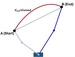
a) TCP Trajectory (curved). Fast but uncontrolled trajectory
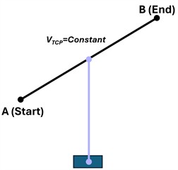
b) LIN Trajectory (linear). Precise and controlled trajectory ensuring uniform silicone thickness
Start-stop motions of the robot at the corners of rectangular cooker hood glasses may lead to silicone accumulation. To address this issue, the FANUC CNT (Continuous) termination type was employed within the system. Instead of reaching the exact corner point, the robot rounds the corner within a predefined tolerance radius. This approach maintains the integrity of the sealing bead by ensuring fluid motion at the corners and preventing the robot's velocity from dropping to zero.
3. Methodology and design of the robotic glass bonding process
The methodology of this study comprises the following stages: analysis of the existing manual process, design of the robotic workstation, establishment of the safety architecture, and development of the control algorithm.
3.1. Workstation design and coexistence study
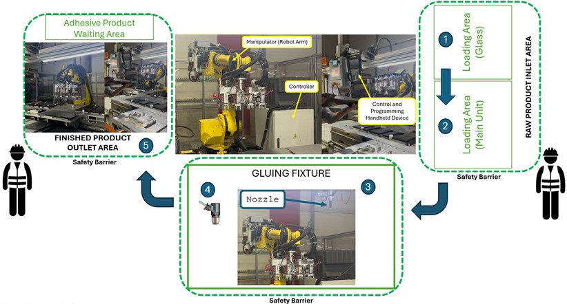
In industrial assembly systems, semi-automated assembly cells, which provide a balance between full automation and manual production, emerge in the literature as a hybrid model that optimizes both flexibility and precision. Within this operating principle, defined as “Coexistence” by [23], humans and robots share the same production goal; however, in compliance with occupational health and safety standards, they perform their actions in different time intervals or segregated spatial zones. In the proposed system, the cognitive flexibility of the operator (quality control, part feeding) is integrated with the kinematic precision of the industrial robot (trajectory tracking, repeatability). The physical layout of the cell is configured based on five primary operational zones, as illustrated in Fig. 3, to minimize material flow while maximizing ergonomic requirements.
The process flow and the interactive synchronous operation between these zones proceed as follows:
Raw Material Feeding and Quality Control (Zones 1-2): The process initiates with the operator loading the raw glass panel onto station (1) and the metal body components (sheet metal, brackets, etc.) onto station (2) within the safety zone. This phase represents the only “human-centric” step of the system; the operator visually inspects the glass surface for potential scratches or screen-printing defects, thereby preventing defective parts from entering the line at the source.
Robotic Manipulation and Preparation: Upon the operator issuing the “Cycle Start” command, the safety barriers are activated, and the FANUC M-710iC/70 robot is engaged. The robot retrieves the glass from area (1) using a vacuum-based hybrid end-effector.
Precision Dispensing (Zone 3): Following the initial handling, the glass panel is transferred to the stationary silicone nozzle located in zone (3) by the manipulator. Here, silicone is applied with micron-level precision to the surfaces where the glass and metal will be joined, utilizing the LIN interpolation technique detailed in Section 2.3. The stationary nozzle and mobile robot architecture (Remote TCP) allow the robot to track complex geometries with greater agility.
Assembly and Curing (Zone 4): Once the silicone application is complete, the part is advanced to the main assembly fixture at station (4) for final integration. The glass panel is aligned and placed onto the metal sheets previously positioned in area (2) by the operator. The pneumatic pistons of the fixture are then activated to apply the pressure required for the adhesive to achieve its initial bond strength.
Discharge and End of Cycle (Zone 5): Once the pressing duration is completed, the fixture opens. The robotic arm or an automated transfer unit moves the assembled product to the finished product output area at station (5). At this point, the system deactivates the light curtain signals to allow the operator to safely retrieve the part and prepares for the subsequent cycle.
This spatial design ensures full compliance with the safety standards for guarded robotic systems detailed by, [13] and [10] while simultaneously supporting lean manufacturing principles by minimizing operator walking distances.
Fig. 3Layout and safety zones of the semi-automated assembly cell
The cell design consists of the following primary components:
– Robotic Manipulator: A 6-axis FANUC M-710iC/70 robot.
– Assembly Fixture: A pneumatically actuated clamping unit ensuring high-precision positioning of glass and sheet metal parts.
– Safety Architecture: Operator safety is ensured through physical barriers and light curtains.
3.2. Operational workflow
With appropriate planning, it is observed that quality is maximized in manual-loading automated assembly lines, which possess lower investment costs compared to fully autonomous systems [24]. In this regard, the robot station features a structure that integrates the flexibility of manual preparation with the stability of high-accuracy, robot-assisted assembly. The process steps depicting the robot-human interaction at the workstation are presented in Fig. 4. At the commencement of the process, the raw glass panel intended for assembly is visually inspected by the operator; if scratches, screen-printing defects, or cracks are identified, the part is rejected as scrap prior to entering the line. Defect-free glass panels are placed in the robot reference area (Fig. 4(a)), and the metal connecting plates and plastic components for the assembly are positioned on the aluminum assembly fixture according to the product recipe, as illustrated in Fig. 4(b). This step, critical for ensuring geometric accuracy, is performed by the operator.
Fig. 4Coexistence process steps. Photo by Altuğ Pirselimoğlu, Amasya, Türkiye, June 12, 2025
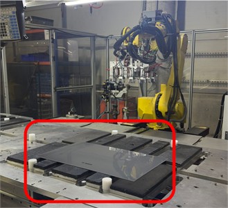
a) Placement of the product glass into the feeding area
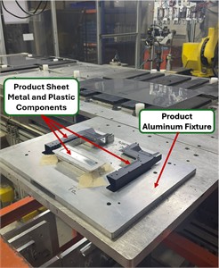
b) Glass fixture with metal plate and plastics
c) Silicone application via remote TCP
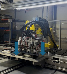
d) Assembly and Pressing.
In the subsequent phase, after the operator moves to the safety zone and issues the start command, the robot grips the glass panel via vacuum using the hybrid end-effector detailed in Fig. 1. The gripped glass is moved along the edge trajectory beneath the stationary nozzle shown in Fig. 4(c) for silicone application. As observed, rather than the conventional method where the silicone gun is mounted on the robot arm, a remote TCP method is employed where the nozzle remains stationary while the part is mobile. This approach prevents the entanglement of robot cables or hoses and ensures a more fluid trajectory tracking. In the following stage, the glass panel, to which silicone has been precisely applied, is transferred to the main assembly fixture shown in Fig. 4(d) for the completion of the assembly process. At this stage, the robot aligns and places the glass panel onto the metal sheets previously positioned by the operator with a precision of ±0.05 mm to prevent the glass from slipping upon contact with the sheets, a vertical (-axis) approach profile is followed using LIN motion commands within the robot program. Finally, during the assembly phase, pneumatic pistons on the fixture are activated to apply controlled pressure for 3 seconds, ensuring uniform distribution of the adhesive and the development of initial bond strength. Upon completion of the process, the robot retracts to the safe home position, and a visual warning is provided to the operator via a signal lamp to indicate that the product can be removed from the finished area.
The operational cycle of the robotic cell is executed within the framework of a logical flow algorithm schematized in Fig. 5, running on the R-30iB Plus control unit. The algorithm follows a closed-loop structure that ensures operator safety and process consistency.
Fig. 5Control flow diagram of the robotic glass bonding process
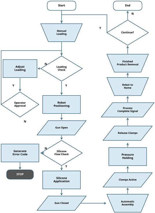
The process in the flow diagram presented in Fig. 5 is triggered by the “Start” step and continues with “Manual Loading”, where the operator places the raw material onto the fixture. To proceed to the autonomous operation phase, approval must be obtained from the “Loading Verification” decision block. At this stage, where sensors on the fixture verify the metal and plastic components of the product, if a loading non-conformity (N) is detected, the system is directed to the “Adjust Loading” step, and corrective action is requested from the operator. Following the adjustment, the process is re-verified to account for potential disruptions (Operator Approval); if the operator approves (Y), the process resumes. In the event of an unforeseen issue (fixture or sensor-originated failures) where operator approval is not granted (N), the system executes the “Generate Error Code” block, creates a fault report, and enters the “STOP” state to await service intervention.
Upon successful verification of the loading (Y), the robot reaches the operation point with a “Robot Positioning” motion, and the “Gun ON” command is issued. Before application, the critical “Silicone Flow Control” step is performed. If a flow problem is detected (N), the system is directed to the “Generate Error Code” block and halted. In the normal scenario where flow is verified (Y), the robot performs the “Silicone Application” along the defined trajectory and switches to the “Gun OFF” position upon completion. During the assembly phase, parts are joined via the “Automated Assembly” step, and the fixture pistons are locked by setting “Clamps ON”. To ensure bonding strength, controlled pressure is applied during the “Pressurized Waiting” period (3 s). At the end of the duration, the pistons are released with the “Clamps OFF” command, and the operator is notified via the “Process Completion Signal”. After the robot retracts to the safe area with a “Return to Home” motion, the operator performs the “Unload Finished Product” operation. At the end of the cycle, the system awaits approval from the operator for the next work cycle via the “Confirmation for Next Cycle” decision block. If the operator grants approval (Y), the system loops back to the “Start” block for a new cycle; if not (N), the system proceeds to the “Finish” state and terminates operation.
3.3. Flow control and mathematical modeling
To achieve a high-quality sealing process, the cross-sectional area of the silicone bead (Bead Geometry) must remain constant regardless of variations in robot speed. An Open-Loop control architecture was implemented in the system to facilitate real-time synchronization between the robot's tangential velocity () and the volumetric flow rate (). The fluid dynamics of the dispensing process were structured based on the model proposed by [15]. Accordingly, the relationship between the nozzle's volumetric flow rate (Nozzle), applied pressure (), and viscosity () is expressed in Eq. (1):
where, represents the nozzle inner diameter (mm), denotes the pressure difference, indicates the fluid viscosity, and corresponds to the nozzle length. However, as viscosity and nozzle geometry are assumed to be constant in industrial applications, the control algorithm is reduced to a proportional relationship between robot speed and flow rate. According to the constant bead width principle detailed by [22], the flow rate must be increased linearly as the robot speed increases. The control structure implemented in the system is integrated into the robot controller via the transfer function provided in Eq. (2):
where, represents the 0-10 V control signal transmitted to the dosing unit, denotes the instantaneous tangential velocity of the robot on the glass surface (mm/s), signifies the calibration coefficient (experimentally determined based on the rheology of the silicone), and corresponds to the valve opening threshold voltage. Specifically, the coefficient was calibrated through an empirical trial-and-error procedure during the initial commissioning phase. Starting from the baseline viscosity of the silicone, the analog output was iteratively adjusted by observing the physical bead width, particularly during maximum robot acceleration and sharp corner decelerations. Furthermore, to effectively manage complex dynamics such as temperature-induced viscosity fluctuations, this calibration is integrated within a closed-loop intelligent control architecture, as suggested in recent analytical studies [15]. By means of this algorithm, when the robot decelerates during cornering, the analog voltage is automatically reduced to fully compensate for the residual volume (RV) inertia inside the nozzle. This dynamic adjustment prevents structural thinning and silicone accumulation (blobbing) at the corners [7], ensuring the bead cross-section remains perfectly stable and maintaining a standardized total silicone consumption of exactly 8.20 ml per cycle.
4. Results and discussion
Findings obtained from field tests regarding system design and robot performance verification validate the accuracy of the system design. In particular, no vibrations were observed during the handling of the glass panel, owing to the high moment of inertia capacity of the robotic arm. Furthermore, by means of LIN interpolation, the robotic axes performed fluid transitions at the sharp corners of the cooker hood glass, which prevented material accumulation issues. Quantitative evaluation based on production metrics indicates that significant improvements were achieved in efficiency and quality indicators with the commissioning of the robotic cell compared to manual processes. Performance data were collected during the 08:00-16:00 and 16:00-24:00 shifts, when the facility was in active production. Within the scope of the study, 500 reference glass panels (500) produced under the supervision of two different operators were examined. The target cycle time for each panel was set at 45 seconds. A comparative analysis of manual and robotic processes, including standard deviation () values, is presented in Table 1.
Table 1Comparison of performance metrics for manual and robotic processes
Performance metric | Manual process (before) | Robotic process (after) | Change / improvement |
Average cycle time | 72.4 s ± 8.6 (σ) | 45.0 s ± 0.4 (σ) | 37.8% Reduction |
Positioning accuracy | ±0.5 mm | ±0.05 mm | 10-fold improvement |
Scrap rate (PPM) | 3.2% (32,000 PPM) | 0.3% (3,000 PPM) | 90 % Decrease |
Silicone consumption (Avg.) | 9.10 ml ± 0.8 | 8.20 ml ± 0.1 | 10 % Savings |
Hourly production (Units) | 50 | 80 | 60 % Increase |
Upon examining the data presented in Table 1, the processing time – which averaged 72.4 seconds with a standard deviation of ±8.6 seconds due to operator-dependent variables in manual operations – was reduced to 45.0 seconds with a deviation of ±0.4 seconds through robotic automation, representing a net improvement of 37.8 %. The primary determinants of this radical reduction were the high point-to-point (PTP) movement speed of 2600 mm/s and the elimination of operator rest requirements. Consequently, the hourly production capacity increased from 50 to 80 units, reflecting a 60 % capacity growth. These findings confirm that coexistence models enhance production stability. Specifically, reducing the time deviation from ±8.6 seconds (associated with operator fatigue in the manual process) to ±0.4 seconds via robotic automation stabilizes the process, demonstrating the impact of automation on sustainability. These results are in full alignment with the thesis proposed by [24], stating that automated loading and assembly systems increase production efficiency while reducing labor costs.
Regarding quality improvement, the scrap rate decreased from 3.2 % (32,000 PPM) in the manual process to just 0.3 % (3,000 PPM) in the robotic system. This exceptional 90 % reduction is primarily attributed to two factors: high positioning precision and active error handling. First, the robot's theoretical repeatability of ±0.03 mm and the implemented flow control algorithm yielded a process accuracy of ±0.05 mm, effectively eliminating human-related adverse effects such as physiological hand tremors. Second, the Generate Error Code diagnostic protocol (referenced in Fig. 5) proved critical during the field tests. The system successfully managed the two most frequent anomalies: sudden drops in pneumatic line pressure and vacuum pad suction losses caused by microscopic glass surface dust. By instantly halting the robot trajectory and sealing the proportional valve during such events, the closed-loop system actively prevented defective bead profiles. Additionally, the synchronization of robot speed and flow rate achieved a 10 % savings in silicone consumption, supporting the economic efficiency of the process. From the perspective of ergonomics and safety, delegating this repetitive, high-concentration task to the robot minimized operator fatigue, validating the success of the human-machine coexistence model.
Finally, when comparing these efficiency gains with existing literature, the proposed system demonstrates superior performance. While conventional Moving Tool configurations typically report cycle time reductions of only 20-25 % due to high inertia constraints and limit defect reductions to around 70-80 %, the kinetic advantage of our “Remote TCP” architecture – utilizing rapid wrist rotations – enabled a 37.8 % cycle time reduction alongside the aforementioned 90 % decrease in scrap rates.
5. Conclusions
The increasing expectations for aesthetics and durability in the home appliances industry have popularized the use of glass materials. This situation has necessitated the replacement of traditional assembly methods with adhesive technologies. This study investigated the effects of transitioning from manual operations to a robotic semi-automated cell. The findings demonstrate that robotic automation reduced the average cycle time by 37.8 %, increased production capacity by 60 %, and decreased the scrap rate by 90 %. Furthermore, the implementation of the Remote TCP strategy yielded a 10-fold improvement in positioning accuracy (from ±0.5 mm to ±0.05 mm) and provided a 10 % savings in adhesive material consumption. The designed coexistence model successfully integrated operator flexibility with robotic precision. For future studies, the addition of vision sensors for real-time bead width monitoring is recommended. Furthermore, integrating closed-loop intelligent control algorithms to autonomously compensate for dynamic viscosity changes caused by varying ambient thermal conditions would allow the system to seamlessly adapt to a wider range of industrial adhesives without the need for manual recalibration.
References
-
D. D. Furszyfer Del Rio et al., “Decarbonizing the glass industry: A critical and systematic review of developments, sociotechnical systems and policy options,” Renewable and Sustainable Energy Reviews, Vol. 155, No. December 2021, p. 111885, 2022, https://doi.org/10.1016/j.rser.2021.111885
-
C. S. P. Borges, A. Akhavan-Safar, P. Tsokanas, R. J. C. Carbas, E. A. S. Marques, and L. F. M. Da Silva, “From fundamental concepts to recent developments in the adhesive bonding technology: a general view,” Discover Mechanical Engineering, Vol. 2, No. 1, May 2023, https://doi.org/10.1007/s44245-023-00014-7
-
S. Veenaas and F. Vollertsen, “Mechanical joining of glass and aluminium,” Key Engineering Materials, Vol. 767, pp. 369–376, Apr. 2018, https://doi.org/10.4028/www.scientific.net/kem.767.369
-
A. Selvanayakam, P. Anbarasu, N. Subhashini, and N. Krishnaveni, “Design and fabrication of automated adhesive dispenser,” in 6th International Conference on Advanced Computing and Communication Systems (ICACCS), pp. 913–915, Mar. 2020, https://doi.org/10.1109/icaccs48705.2020.9074271
-
B. Tiwari, C. Clevy, and P. Lutz, “High-precision gluing tasks based on thick films of glue and a microrobotics approach,” IEEE Robotics and Automation Letters, Vol. 4, No. 4, pp. 4370–4377, Oct. 2019, https://doi.org/10.1109/lra.2019.2932881
-
J. Zou, M. Huang, D. Zhao, F. Chen, and D. Wang, “Modeling the contact dispensing process of conductive adhesives with different viscosities and optimization of droplet deposition,” Frontiers in Materials, Vol. 10, No. May, pp. 1–13, May 2023, https://doi.org/10.3389/fmats.2023.1183747
-
A. Kazemian, X. Yuan, O. Davtalab, and B. Khoshnevis, “Computer vision for real-time extrusion quality monitoring and control in robotic construction,” Automation in Construction, Vol. 101, No. January, pp. 92–98, 2019, https://doi.org/10.1016/j.autcon.2019.01.022
-
“EAA Aluminium Automotive Manual – Hybrid joining techniques,” European Aluminium Association, 2015.
-
I. Iturrate, A. Kramberger, and C. Sloth, “Quick setup of force-controlled industrial gluing tasks using learning from demonstration,” Frontiers in Robotics and AI, Vol. 8, No. November, pp. 1–18, 2021, https://doi.org/10.3389/frobt.2021.767878
-
V. Gopinath, K. Johansen, M. Derelöv, Gustafsson, and S. Axelsson, “Safe collaborative assembly on a continuously moving line with large industrial robots,” Robotics and Computer-Integrated Manufacturing, Vol. 67, No. August 2020, p. 102048, 2021, https://doi.org/10.1016/j.rcim.2020.102048
-
P. Mesmer, P. Riedel, A. Lechler, and A. Verl, “Investigation and compensation of hysteresis in robot joints with cycloidal drives,” in Annals of Scientific Society for Assembly, Handling and Industrial Robotics, Cham: Springer International Publishing, 2023, pp. 177–187, https://doi.org/10.1007/978-3-031-10071-0_15
-
“Fanuc robot M-710iC/50/70/50H/50S/45M/50E operator’s manual,” FANUC, 2017.
-
E. Magrini, F. Ferraguti, A. J. Ronga, F. Pini, A. de Luca, and F. Leali, “Human-robot coexistence and interaction in open industrial cells,” Robotics and Computer-Integrated Manufacturing, Vol. 61, No. June 2018, p. 101846, 2020, https://doi.org/10.1016/j.rcim.2019.101846
-
C. Galitsky, E. Worrell, C. Galitsky, E. Masanet, and W. Graus, “Energy efficiency improvement and cost saving opportunities for the glass industry. an energy star guide for energy and plant managers,” Office of Scientific and Technical Information (OSTI), Berkeley, CA, Mar. 2008, https://doi.org/10.2172/927883
-
Y. Liu, Y. Yao, L. Chen, and L. Sun, “A closed-loop intelligent control strategy for precise non-contact liquid dispensing,” in IEEE International Conference on Mechatronics and Automation, pp. 957–962, Aug. 2010, https://doi.org/10.1109/icma.2010.5588527
-
Hitzer and E. M. S., “Early works on the Hagen-Poiseuille flow,” Memoirs of the Faculty of Engineering, Fukui University, Vol. 49, 2001.
-
J. Pfitzner, “Poiseuille and his law,” Anaesthesia, Vol. 31, No. 2, pp. 273–275, 1976, https://doi.org/10.1111/j.1365-2044.1976.tb11804.x
-
B. Balog and P. Nagy-György, “Application ranges of the Hagen-Poiseuille law to model non-Newtonian fluid-filled dampers,” in Proceedings of the Conference on Modelling Fluid Flow CMFF’25, pp. 537–544, 2025.
-
“Cutting, Painting and Remote TCP with ABB IRB 1200-5/0.9 and more robots.” RoboDK. https://robodk.com/example/cutting-painting-and-remote-tcp-with-abb-and-fanuc (accessed 2026).
-
“Remote tcp example: sheet metal deburring.” Universal Robots. https://www.universal-robots.com/articles/ur/application-installation/remote-tcp-example-sheet-metal-deburring (accessed 2026).
-
“Education cell student exercises student exercises,” FANUC, 2020.
-
A. Yashwanth, K. Rishwanth, and M. P. Anbarasi, “Robotics arm based 3d food printing: design, challenges, and feasibility for culinary automation,” International Journal for Research in Applied Science and Engineering Technology, Vol. 14, No. 2, pp. 1505–1520, 2026, https://doi.org/10.22214/ijraset.2026.77700
-
A. Dzedzickis, J. Subačiūtė-Žemaitienė, E. Šutinys, U. Samukaitė-Bubnienė, and V. Bučinskas, “Advanced applications of industrial robotics: New trends and possibilities,” Applied Sciences, Vol. 12, No. 1, p. 135, Dec. 2021, https://doi.org/10.3390/app12010135
-
F. Sherwani, M. M. Asad, and B. S. K. K. Ibrahim, “Collaborative robots and industrial revolution 4.0 (ir 4.0),” in International Conference on Emerging Trends in Smart Technologies (ICETST), pp. 1–5, Mar. 2020, https://doi.org/10.1109/icetst49965.2020.9080724
About this article

The authors have not disclosed any funding.
The authors would like to thank the management and technical team of Silverline Endüstri ve Ticaret A.Ş. for providing the infrastructure, technical equipment, and production line access necessary for the experimental processes of this study. Furthermore, gratitude is extended to the plant engineers for their valuable contributions during the system installation phase.
The datasets generated during and/or analyzed during the current study are available from the corresponding author on reasonable request.
Altuğ Pirselimoğlu: conceptualization, methodology, formal analysis, investigation, writing-original draft preparation, writing-review and editing. Berkan Zöhra: conceptualization, methodology, formal analysis, investigation, writing-original draft preparation, writing-review and editing. All authors have read and agreed to the published version of the manuscript.
The authors declare that they have no conflict of interest.
