Abstract
Assessing the post-breakage performance of fractured laminated glass (LG) is challenging due to the complexity of damage progression. This study investigates the dynamic behavior of small-scale, through-cracked LG elements composed of two layers of annealed glass, bonded with different interlayers. Using a three-point-bending setup, the specimens were subjected to ten repeated hard-body impacts. To quantify the residual bending stiffness as a function of damage severity, experimental modal analyses were conducted via roving hammer tests, prior to and following each impact. The fundamental vibration frequency was utilized as preliminary diagnostic parameter. Experimental frequency estimates, supported by simplified finite element (FE) numerical modelling, reveal markedly distinct degradation patterns for the tested configurations.
Highlights
- Both specimens maintained significant post-fracture mechanical capacity even after ten repeated hard-body impacts.
- The fundamental vibration frequency proved to be an effective diagnostic parameter, successfully tracking modifications in mechanical parameters and residual capacity as damage severity increases.
- EVA specimen exhibited an interlocking phenomenon at the fourth impact, where the adjustment of glass fragments caused a temporary increase in frequency, highlighting complex non-linear post-breakage behavior.
- A simplified FE model using a lumped rotational spring accurately predicted SG performance with a 0.8% mean error, but overestimated EVA capacity by 20.1% due to the inability to capture complex fragment interactions.
- SG specimen showed a stable frequency trend with only a 15% reduction in rotational stiffness after ten impacts, whereas EVA specimen suffered severe degradation, reaching an 83% loss.
1. Introduction
The post-breakage behaviour of laminated glass elements constitutes a rather complex research topic due to a multitude of influencing parameters [1,2]. In this regard, quantifying the residual capacity and its evolution as damage severity increases is of fundamental importance in ensuring adequate safety levels [3]. The present study takes advantage of an experimental investigation on small-scale, pre-fractured LG samples carried out with the primary goal represented by the dynamic characterization and quantification of the residual mechanical capacity as the severity of the damage increases [4]. To this aim, the samples are exposed to a series of consecutive hard-body impacts and experimental modal analyses to assess any propagation of damage and reduction in the residual capacity. The fundamental vibration frequency is tracked as a key performance indicator, given that frequency changes are well-known to represent modifications in the mechanical parameters of the examined specimen. In order to facilitate the examination of experimental outcomes, a simplified finite element (FE) numerical model is also developed in ABAQUS [5] to investigate the frequency trend as a function of the imposed damage.
2. Experimental testing and results
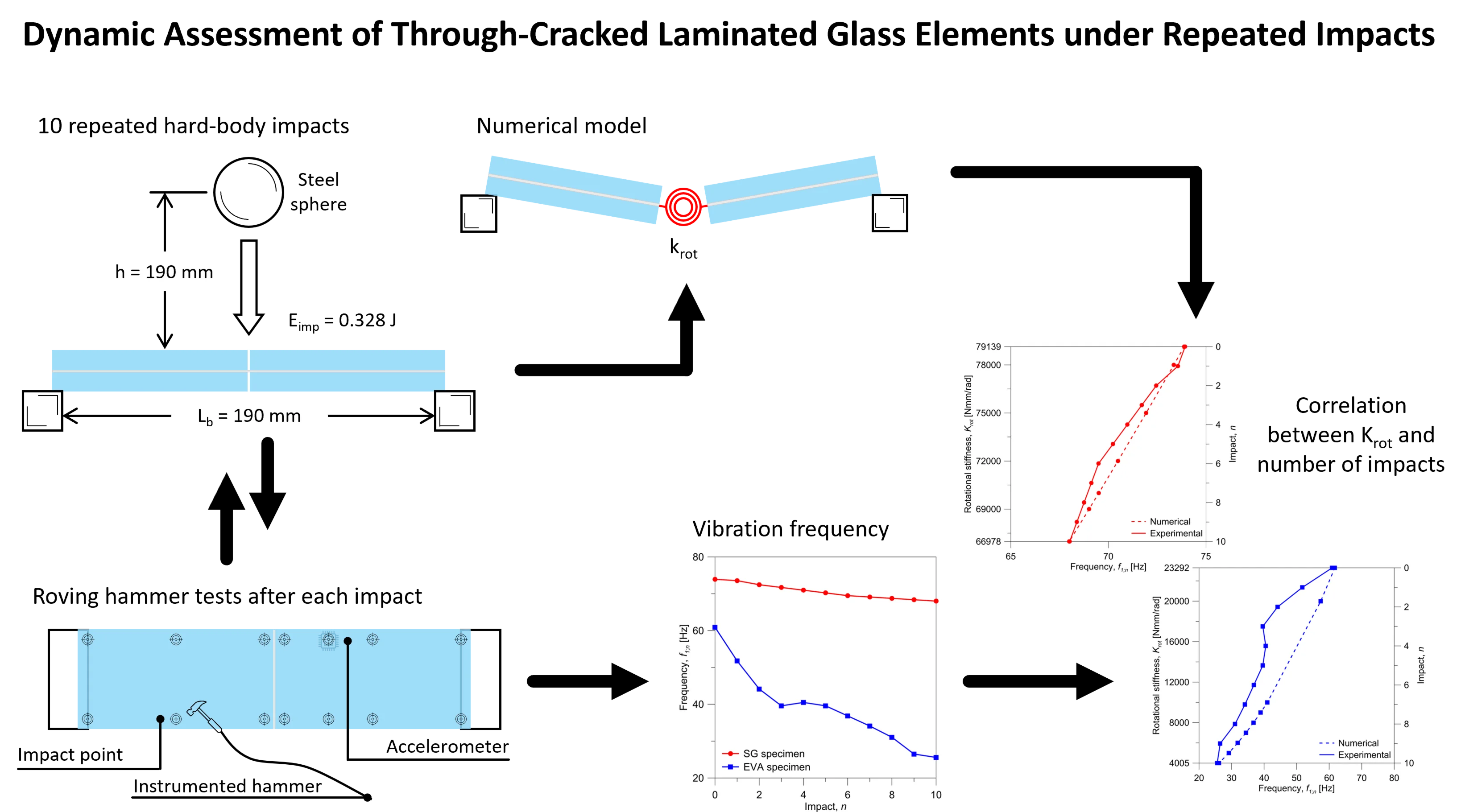
The experimental investigation reported in [4] comprised a series of low-velocity, hard-body impacts on LG samples in a three-point-bending setup, alternated with roving hammer tests for their dynamic characterization. The main features of the tested specimens are summarized in Table 1 and Fig. 1.
Table 1Features of tested specimens (values in mm)
Specimen label | Length | Width | Glass thickness nominal / measured | Interlayer thickness | Interlayer type |
EVA | 200 | 50 | 4 / 3.814 | 1.52 | Evalam Visual |
SG | 200 | 50 | 10 / 9.766 | 0.76 | SentryGlas SG5000 |
The samples were produced with a disconnection at the mid-span section, in order to reproduce a through-cracked sample for assessing the bonding capacity of interlayers [6, 7].
The series of 10 impact tests were carried out positioning the sample on two rigid blocks, ensuring a free total span 190 mm. As illustrated in Fig. 1(a), a steel sphere with a diameter 35 mm and a mass 0.18 kg was released from a fixed height 190 mm towards the mid-span section of the specimen. The setup in Fig. 1(a) corresponded to an impact energy of 0.328 J.
Fig. 1Experimental setups (out-of-scale). Figure adapted from [4] based on the terms and conditions of a CC-BY license agreement
![Experimental setups (out-of-scale). Figure adapted from [4] based on the terms and conditions of a CC-BY license agreement](https://static-01.extrica.com/articles/26345/26345-img1.jpg)
a) Hard-body impact test (lateral view)
![Experimental setups (out-of-scale). Figure adapted from [4] based on the terms and conditions of a CC-BY license agreement](https://static-01.extrica.com/articles/26345/26345-img2.jpg)
b) Roving hammer test (top view)
To quantify any potential propagation of damage due to the repeated hard-body testing protocol, experimental modal analyses were performed on each LG specimen, both prior to the impact tests and after each impact [4]. The modal analysis was conducted with an instrumented modal hammer and a total of #14 control points (3 hammer hits each), arranged as shown in Fig. 1(b). Vibrations measurements were obtained using a micro single-axis accelerometer, which was bonded to the glass close to the mid-span section; see Fig. 1(b).
The EVA bonded specimen exhibited clear indications of severe degradation under the imposed impacts, manifesting crack propagation in the region of impact. In contrast, no cracks were visually detected in the SG specimen, following hard-body impacts. In both cases, no damage phenomena were observed in the EVA or SG interlayers. A selection of examples is presented in Fig. 2(a) and (b).
Fig. 2Selected details of damage propagation after n repeated hard-body impacts. Figure adapted from [4] based on the terms and conditions of a CC-BY license agreement
![Selected details of damage propagation after n repeated hard-body impacts. Figure adapted from [4] based on the terms and conditions of a CC-BY license agreement](https://static-01.extrica.com/articles/26345/26345-img3.jpg)
a) EVA specimen (3)
![Selected details of damage propagation after n repeated hard-body impacts. Figure adapted from [4] based on the terms and conditions of a CC-BY license agreement](https://static-01.extrica.com/articles/26345/26345-img4.jpg)
b) SG specimen (1)
The post-processing of experimental data collected from the roving hammer tests was focused on the examination of the fundamental vibration frequency, which is widely employed as monitoring parameter. Assuming as the vibration frequency of the through-cracked specimen prior to the first impact test ( 0), it can be expected that:
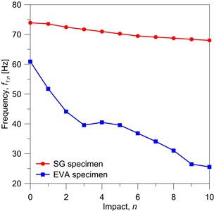
This trend is confirmed by the experimental fundamental frequencies depicted in Fig. 3, where a different progression of damage for the EVA- and SG-bonded specimens can be seen. Specifically, the latter exhibits a relatively stable trend, with a slight frequency reduction with n. Given that the glass layers did not manifest major cracks, this reduction is likely attributable to the deterioration of the SG interlayer at the mid-span section. In contrast, the EVA specimen demonstrates a higher frequency reduction with n. Both phenomena can be explained by considering the ticker glass layers and stiffer interlayer employed for the SG specimen. The trend of experimental data for the EVA specimen also differs from the general expectation summarized by Eq. (1), highlighting the occurrence of a significant interlocking phenomenon with n. Specifically, the experimental vibration frequency displays a slight increase for 4. This phenomenon could be justified by the greater deformability of the EVA specimen, which facilitates the interlocking of two major glass fragments. This, in turn, leads to an increase in stiffness and, consequently, a positive change in the natural vibration frequency.
Fig. 3Experimental vibration frequency as a function of n repeated hard-body impacts
3. Simplified numerical model
To support the interpretation of experimental findings, a simple FE model was taken into account for linear modal frequency analyses of the tested specimens. The resisting mechanism of a through-cracked specimen in out-of-plane bending can in fact be described with reference to the stress distribution highlighted in Fig. 4(a) [8, 9]. The load-bearing capacity of the sample lies in the rotational equilibrium offered by the bridging contribution of the interlayer and the contact of the glass layers on the compressive side. Obviously, the interlayer properties are of major importance in defining the residual stiffness and strength of the LG package in this configuration.
Fig. 4Modelling of a through-cracked specimen. Figure adapted from [4] based on the terms and conditions of a CC-BY license agreement
![Modelling of a through-cracked specimen. Figure adapted from [4] based on the terms and conditions of a CC-BY license agreement](https://static-01.extrica.com/articles/26345/26345-img6.jpg)
a) Stress distribution
![Modelling of a through-cracked specimen. Figure adapted from [4] based on the terms and conditions of a CC-BY license agreement](https://static-01.extrica.com/articles/26345/26345-img7.jpg)
b) Lumped rotational spring
The through-cracked LG sample can be described in terms of a simplified model in which the mid-span crack is replaced by a lumped rotational spring with stiffness between two rigid LG arms, see Fig. 4(b) and [4, 10, 11]. can range from ∞ to 0. ∞ ideally represents the intact LG specimen, whereas 0 the fully damaged LG sample without any residual mechanical interaction between the arms.
This model was implemented in ABAQUS, where the cross-section and size of each specimen were defined based on Section 2. The rigid blocks at the ends were reproduced by means of distributed equivalent nodal restraints, while the mass of the accelerometer sensor was neglected.
Incompatible mode, 8-node brick elements (C3D8I type) were used for the LG parts, to accurately capture the flexural behavior. Following a preliminary sensitivity study, the chosen mesh pattern included three elements in the thickness of each layer, with a maximum edge size of 5 mm. This choice resulted in 3,600 elements and 46,500 DOFs.
Input material properties for glass and interlayers were described based on linear elastic constitutive models. For annealed glass, the modulus of elasticity was set at 70 GPa, with 0.23 the Poisson’ ratio and 2,500 kg/m3 the material density. EVA and SG were mechanically described based on available technical data sheets ( 0.45, 925 kg/m3 and 0.45, 950 kg/m3). Careful attention was indeed paid to their elastic modulus, resulting in experimental estimates of 9.7 MPa and 198 MPa [4].
4. Discussion of numerical results
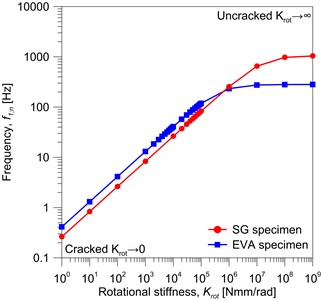
The FE numerical model was preliminary validated in the intact configuration, towards analytical formulation available in literature [12], and successively adapted for the parametric study. The sensitivity of to the rotational stiffness and thus to the damage imposed through hard-body impacts was explored. To this aim, the input stiffness was parametrically modified in a range of 100-109 Nmm/rad, as shown in Fig. 5(a).
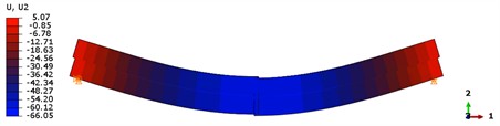
Fig. 5Numerical vibration frequency and shape as a function of the spring rotational stiffness
a) Numerical trend
b) Modal shape for 109 Nmm/rad (SG specimen)
c) Modal shape for 100 Nmm/rad (SG specimen)
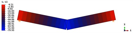
It can be observed that as approaches 0 (i.e., fully damaged specimen), the vibration frequency drastically decreases. The SG specimen exhibits a higher frequency in the intact configuration () due to the thicker glass plates. However, with the progressive reduction of , the frequency of the EVA specimen increases relative to the SG sample, highlighting a relevant modification in the flexural behaviour of the LG package. This modification is clearly visible also from the predicted fundamental modal shapes, as shown in Fig. 5(b) and (c). For higher values of (see Fig. 5(b)), the vibration shape approaches the flexural shape of a simply supported beam. It is also possible to observe the shear sliding of the two glass panes due to the interlayer flexibility. Conversely, when tends to 0 (see Fig. 5(c)), the two LG arms behave as rigid bodies, and no shear sliding is visible.
As shown in Fig. 5(a), for values lower than ≈ 105, a good approximation of the numerical relationship between and can be obtained using a power function, which is also emphasized in Fig. 6. Taking advantage of the reported fitting equations, it is thus possible to focus more in detail on the combined analysis of experimental and numerical results, and to investigate the correlation between and . A quantitative comparison of numerical and experimental evidences for can be found in Fig. 7. It is worth noting that a relatively high range of rotational stiffnesses was identified for both the specimens, demonstrating that a certain degree of post-breakage stiffness can be ensured even after repeated hard-body impacts. As a direct consequence of the thicker glass layers and stiffer interlayer, and thus the lower severity of the impacts, the SG specimen shows a less severe degradation in terms of rotational stiffness, which is in the order of about –15 % after 10 hard-body impacts. The EVA sample, on the other hand, appears to be more seriously affected by the repeated impacts, with a reduction down to –17 % after two impacts ( 2) that progressively increases to –83 % at the end of the series of impacts ( 10).
Fig. 6Fitting equation for the trend of vibration frequency, as a function of the spring rotational stiffness
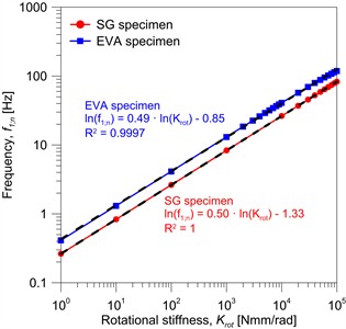
Fig. 7Experimental and numerical comparative analysis of vibration frequency
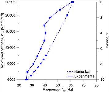
a) EVA specimen
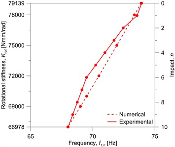
b) SG specimen
In terms of numerical prediction of the experimental trend as a function of n, a better correlation was observed for the SG specimen. A mean percentage error of +0.8 % was found across estimates from 1 to 9, with a peak value of +1.4 % for 6, highlighting a damage trend – and thus a reduction in frequency – in line with the numerical predictions. More complex phenomena occurred throughout the testing of the EVA specimen. The experimental vibration frequency in Fig. 7(a) exhibits a pronounced decrease up to 3, followed by a slight increase for 4, which could reflect a more severe initial damage and an adjustment of the glass fragments, that the model is unable to capture. For 4, the experimental trend tends to align with the numerical results. Consequently, the model overestimates the experimental fundamental vibration frequency by an average of +20.1 %, with a peak value up to +33.7 % for 3.
In conclusion, the presented comparison emphasises the complexity of the post-breakage behaviour of LG elements and the inherent difficulties in assessing the residual capacity and bending stiffness of fractured specimens subjected to repeated hard-body impacts. In particular, the proposed simplified model with a lumped rotational spring exhibits some important limitations, such as the complexity of a sound calibration of a value representative of the actual damage state of the investigated LG component, due to the occurrence of complex non-linear phenomena with .
5. Conclusions
This paper focused on the analysis of small-scale laminated glass (LG) samples by means of low-velocity, hard-body impact tests. The reference specimens were characterized by a mid-span fracture in the glass layers, as well as by the use of two different interlayers, the Evalam Visual (EVA) and the SG5000 (SG) commercial products. The analysis of results was focused on the change of the fundamental vibration frequency, highlighting a markedly different response of specimens to the repeated hard-body impacts. To further investigate their damaged dynamic response, a simplified numerical model was implemented in ABAQUS. Although the parametric study revealed the complexity of the post-fracture mechanical performance but also confirmed the occurrence of phenomena that ensure a certain residual capacity to cracked LG elements, further experimental investigations are required to extend the results obtained from small-scale specimens to real LG structures.
References
-
C. Bedon, M. Kozłowski, and N. Cella, “Gaps in the post-breakage out-of-plane bending stiffness assessment of 2-ply partially damaged laminated glass elements under short-term quasi-static loads,” Engineering Structures, Vol. 327, p. 119617, Mar. 2025, https://doi.org/10.1016/j.engstruct.2025.119617
-
C. Bedon, R. Del Bello, N. Cella, L. Cozzarini, and M. Fasan, “Residual mechanical capacity of small-scale partially fractured annealed laminated glass elements subjected to a quasi-static cyclic protocol,” Engineering Failure Analysis, Vol. 186, No. 3, p. 110462, Mar. 2026, https://doi.org/10.1016/j.engfailanal.2025.110462
-
M. Feldmann et al., “The new CEN/TS 19100: Design of glass structures,” Glass Structures and Engineering, Vol. 8, No. 3, pp. 317–337, Mar. 2023, https://doi.org/10.1007/s40940-023-00219-y
-
C. Bedon, N. Cella, and R. Del Bello, “Damage assessment of through-cracked-bending laminated glass elements under low-velocity hard-body impacts,” Materials, Vol. 18, No. 19, p. 4454, Sep. 2025, https://doi.org/10.3390/ma18194454
-
“Abaqus Computer Software,” Simulia, Providence, RI, USA, 2025.
-
S. Chen, Z. Chen, X. Chen, and J. Schneider, “Evaluation of the delamination performance of polyvinyl-butyral laminated glass by through-cracked tensile tests,” Construction and Building Materials, Vol. 341, p. 127914, Jul. 2022, https://doi.org/10.1016/j.conbuildmat.2022.127914
-
D. Ferretti, M. Rossi, and G. Royer-Carfagni, “Through-cracked tensile delamination tests with photoelastic measurements,” in Challenging Glass 3, pp. 641–652, 2012, https://doi.org/10.3233/978-1-61499-061-1-641
-
J. Belis, D. Delincé, D. Callewaert, R. van Impe, and J. Depauw, “Plastic deformation of polymer interlayers during post-breakage behavior of laminated glass – Partim 1: analytical approach,” in Engineering Plasticity and Its Applications from Nanoscale to Macroscale, pp. 137–142, Apr. 2012, https://doi.org/10.1142/9789814261579_0022
-
D. Delincé, D. Callewaert, W. Vanlaere, J. Belis, and J. Depauw, “Plastic deformation of polymer interlayers during post-breakage behavior of laminated glass – Partim 2: experimental validation,” in Engineering Plasticity and Its Applications from Nanoscale to Macroscale, pp. 75–80, Apr. 2012, https://doi.org/10.1142/9789814261579_0012
-
C. Bedon and F. A. Santos, “Effects of post-fracture repeated impacts and short-term temperature gradients on monolithic glass elements bonded by safety films,” Composite Structures, Vol. 319, p. 117166, Sep. 2023, https://doi.org/10.1016/j.compstruct.2023.117166
-
C. Bedon and M. Fasan, “Post-fracture stiffness and residual capacity assessment of film-retrofitted monolithic glass elements by frequency change,” Mathematical Problems in Engineering, Vol. 2024, No. 1, pp. 1–16, Jan. 2024, https://doi.org/10.1155/2024/8922303
-
A. Zemanová, J. Zeman, T. Janda, J. Schmidt, and M. Šejnoha, “On modal analysis of laminated glass: Usability of simplified methods and enhanced effective thickness,” Composites Part B: Engineering, Vol. 151, No. 8, pp. 92–105, Oct. 2018, https://doi.org/10.1016/j.compositesb.2018.05.032
About this article

These research activities are financially supported by the Italian Ministry of University and Research (MUR) via the FIS2021 Starting Grant (FIS00000609), www.hopglaz.it.
The datasets generated during and/or analyzed during the current study are available from the corresponding author on reasonable request.
Prof. Chiara Bedon is a chair of the 75th International Conference on Vibroengineering and was not involved in the editorial review and/or the decision to publish this article.
