Abstract
During the stud welding process, residual stresses are inevitably induced due to the significant temperature gradients and associated heterogeneous thermal expansion and contraction. These residual stresses significantly influence the mechanical properties of the welded structure. Quantitative evaluation of the welding residual stress distribution on the steel plate surface was performed using X-ray diffraction (XRD) and the blind-hole method. Results demonstrate that the radial residual stress initially increases and subsequently decreases with increasing distance from the weld ring. The circumferential residual stress is characterized as compressive throughout the measured region, also exhibiting an initial increase, followed by a decrease, and a subsequent increase with greater distance from the weld center. Both radial and circumferential stresses form a compressive stress zone within the weld and its immediate vicinity, with a peak value of approximately 170 MPa. The significant solid-state phase transformations occurring in the weld metal and the adjacent heat-affected zone lead to the development of compressive stresses upon cooling. The compressive stresses observed in the base metal region, far from the weld, are likely attributable to the initial rolling stresses inherent to the steel plate.
1. Introduction
Steel-concrete composite girder bridges are being increasingly widely used in the construction of modern highway bridges. Stud connectors are key components in steel-concrete composite girders that ensure composite action between the steel and concrete, and are primarily connected to the steel member via welding. During the stud welding process, welding residual stresses are inevitably generated due to temperature gradients inherent in the process [1]. These residual stresses subsequently affect the mechanical properties of the material. For instance, considering the fatigue issues commonly observed in modern steel-concrete composite bridge decks, residual stresses can reduce the fatigue limit [2], promote the initiation and propagation of cracks [3], and consequently impact the fatigue life of the structure [4-5]. Therefore, investigating the distribution of residual stresses in stud welds can provide a theoretical basis and technical support for the safe application and accurate assessment of steel-concrete composite bridge decks.
Numerous experimental and numerical studies on welding residual stresses have been conducted by scholars worldwide.
Wang et al. [6] performed fatigue tests on stud push-out specimens, analyzing the influence of parameters such as the fatigue load ratio and amplitude on the deflection of composite girders. They concluded that when the ratio of stud diameter to steel plate thickness is relatively large, initial fatigue cracks are likely to initiate in the steel plate near the stud due to the combined effects of welding residual stress and stress concentration induced by shear force from the stud. Sjaarda et al. [7] experimentally investigated the fatigue performance of welded shear studs in prefabricated composite girders. Their research demonstrated that fatigue failure of the studs initiates in the base metal at the heat-affected zone of the weld root. It was also indicated that the residual stress generated from stud welding can reach the material's yield stress. Gadallah et al. [8] employed the contour method to measure the residual stress distribution at the weld root of rib-to-deck plate connections, obtaining a complete two-dimensional distribution of residual stress on the cut surface. Taraphdar et al. [9] studied the effects of different weld groove shapes, restraint conditions, and mechanical tensioning on the residual stress distribution in 40 mm thick high-strength low-alloy steel butt welds, providing support for controlling welding residual stresses. Wei et al. [10] established a numerical model of a stud using ABAQUS to investigate the influence of low-temperature environments on the distribution of stud welding residual stress. Zhu et al. [11] developed a sequentially coupled thermal-stress finite element model for large-diameter stud welding. This model was used to study the magnitude and distribution patterns of the welding temperature field and residual stress field in large-diameter studs, clarifying the underlying mechanism of residual stress generation.
While previous studies on welding residual stresses in steel-concrete composite structures have mainly focused on conventional techniques or single measurement methods, this study offers a novel contribution by presenting a comparative analysis of stud welding using both X-ray diffraction and the blind-hole method. The resultant welding residual stress distribution was obtained, and a comparison of the results from these two methods was conducted to verify their validity. The findings reveal stress characteristics specific to the stud welding process that have been rarely detailed in existing literature, and can provide theoretical support for subsequent studies on the mechanical performance and fatigue behavior of steel bridge decks.
2. Test study on residual stresses in stud welding
To determine the distribution pattern of residual stresses in stud welds, both X-ray diffraction and the blind-hole method for measurement are employed in this study. The X-ray diffraction (XRD) technique enables non-destructive evaluation of surface residual stresses by measuring interplanar crystal lattice spacing variations through the method. Complementarily, the semi-destructive blind-hole method involves incremental drilling at measurement points and records strain releases via strain gauges to quantify the magnitude and direction of principal stresses. This combined approach allows for comprehensive characterization of both near-surface and subsurface stress profiles, improving measurement reliability by cross-validating results obtained from both techniques.
2.1. X-ray diffraction method for measuring stud welding residual stress
The X-ray diffraction method is based on Bragg’s Law and the method for residual stress measurement. The experiment used a Cr-Kα radiation source, targeting the ferritic (211) crystal plane with a diffraction angle (2) of approximately 156°. angles were set at 0°, 25°, 35°, and 45° for measurement. The stress value was calculated by linearly fitting the curve. To improve accuracy, each measurement point was tested three times and averaged. A standard stress-free sample was used to calibrate instrument error. Before measurement, the sample surface was subjected to electropolishing to eliminate surface stresses induced by mechanical processing, ensuring that the results accurately reflected welding-induced residual stresses.
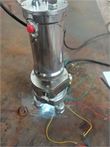
The test material used was Q345B steel. The testing equipment included an X-ray stress analyzer. At room temperature, the elastic modulus of Q345B steel is 200 GPa, its Poisson’s ratio is 0.3, density is 8000 kg/m3, and yield strength is 345 MPa. The stud welding process is illustrated in Fig. 1. Initially, the stud is in contact with the base metal. Subsequently, the stud is lifted to draw an arc, which melts both the stud and the surface of the base metal. After the molten weld pool is formed, the stud is plunged into the pool. The welded joint is formed uponcooling.
The X-ray diffraction measurement scheme is summarized in Fig. 2. Radial and circumferential residual stresses were measured along four orthogonal directions from the weld toe. Eight measurement points were spaced at 5-75 mm in each direction to cover the weld zone, heat-affected zone, and base material.
Fig. 1Stud welding process
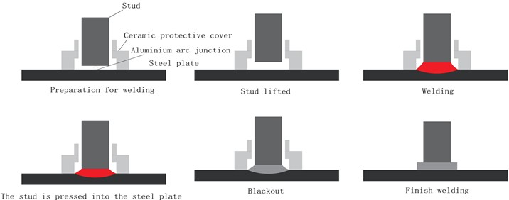
Fig. 2Welding residual stress measurement scheme via X-Ray diffraction method. All photographs were taken by Yuhao Liu in Guangzhou, China, on September 15, 2025
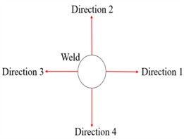
a) Measurement direction
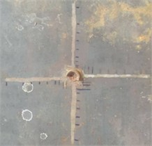
b) Measurement points layout
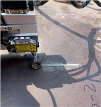
c) Measured welding residual stress
2.2. Residual stress measurement in stud welds using the blind-hole method
A three-element strain gauge rosette (0°-45°-90° layout) was used, with strict alignment to the center of each measurement point. A high-speed pneumatic drilling device with a drill bit diameter of 1.8 mm was employed. The drilling depth was controlled at 2.0 mm, executed in four steps (0.5 mm per step), with strain release values recorded at each increment. Strain data were acquired using a static strain instrument with a sampling frequency of 1 Hz to ensure stability. Stress calculation followed the ASTM E837 standard formula:
where and are calibration coefficients related to the material’s elastic modulus and Poisson’s ratio.
The primary steps for measuring stud welding residual stress using the blind-hole method are as follows: (1) The measurement points are ground, cleaned, and a strain gauge rosette is attached and connected to a strain data acquisition system. (2) A blind hole is drilled at the center of the rosette, and the released strain is recorded. (3) The residual stress at all measurement points is subsequently calculated through data processing. The test material used in this study was Q345B steel. The testing equipment is listed in Fig. 3.
The blind-hole measurement scheme is summarized in Fig. 4. Radial and circumferential residual stresses were measured along one direction at four distances (5, 20, 35, and 50 mm) from the weld toe.
Fig. 3Residual stress testing equipment for the blind-hole method. All photographs were taken by Yuhao Liu in Guangzhou, China, on September 20, 2025
a) Blind-hole drilling unit
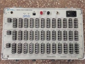
b) Strain gauge demodulation equipment
Fig. 4Welding residual stress measurement scheme via the blind-hole method
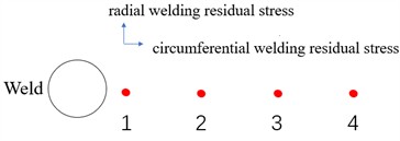
a) Measurement points layout
b) Measured welding residual stress
3. Results analysis
3.1. Results of radial welding residual stress measurement
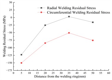
The radial welding residual stresses obtained from the X-ray diffraction method and the blind-hole method are shown in Fig. 5, where the black line represents the results from the X-ray diffraction method and the red line represents the results from the blind-hole method.
As can be seen from Fig. 5, the radial welding residual stress exhibits a trend of first increasing and then decreasing as the distance from the weld ring increases. The maximum radial welding residual stress, recorded at –170 MPa, occurs at a distance of 5 mm from the weld ring. As the distance from the weld ring increases further, the compressive stress gradually transitions into tensile stress, with a maximum tensile stress of 40 MPa. Subsequently, with increasing distance from the weld center, the radial welding residual tensile stress gradually transforms back into compressive stress. This “compression-tension-compression” three-stage distribution pattern is significantly different from the distribution characteristics of the weld area in the classical welding residual stress theory, which mainly shows tensile stress.
3.2. Results of circumferential welding residual stress measurement
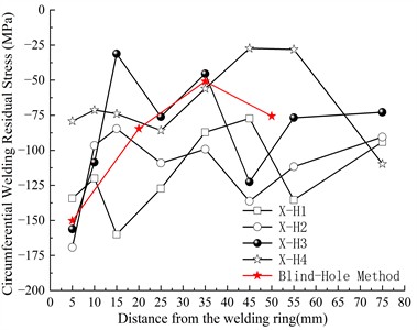
The circumferential welding residual stresses obtained via the X-ray diffraction method and the blind-hole method are presented in Fig. 6, where the black line and red line denote the results from the X-ray diffraction method and the blind-hole method, respectively.
As observed in Fig. 6, the circumferential welding residual stress consistently exhibits a compressive stress distribution. Furthermore, its magnitude demonstrates a trend of initially increasing, then decreasing, and subsequently increasing again as the distance from the weld ring increases. The maximum circumferential welding residual stress reaches –170 MPa at a location 5 mm from the weld ring. With increasing distance from the weld ring, the compressive stress first increases and then decreases. Beyond this point, as the distance from the weld ring continues to increase, the circumferential welding residual compressive stress gradually rises again, eventually stabilizing at approximately -100 MPa, which indicates that even if the material is far away from the heat source, there is still non-negligible residual compressive stress in the material.
Fig. 5Distribution of radial welding residual stress
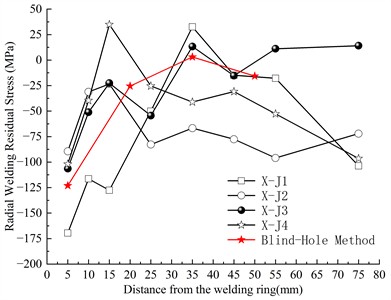
Fig. 6Distribution of circumferential welding residual stress
3.3. Stress distribution mechanism analysis
Analysis of the welding residual stress measurement results reveals a compressive stress distribution in both the region immediately adjacent to the weld ring and the base metal area far from the weld, with a tensile stress region in between. The weld zone and its immediate vicinity exhibit high compressive stress (–170 MPa), while areas further away show low tensile stress (40 MPa). This pattern is opposite to the classic welding residual stress distribution, where the weld zone typically experiences tensile stress.
Table 1Quantitative comparison of residual stress measurements by XRD and blind-hole methods
Parameter | XRD | Blind-hole | Difference |
Peak radial stress (MPa) | –170 | –123 | –47 MPa (28 %) |
Location of peak radial stress (mm from weld toe) | 5 | 5 | |
Peak circumferential stress (MPa) | –169 | –150 | –19 MPa (11 %) |
Location of peak circumferential stress (mm from weld toe) | 5 | 5 |
The reasons for this phenomenon may be as follows:
(1) A significant solid-state phase transformation (primarily the transformation of austenite to martensite or bainite) occurred in the weld metal and the nearby heat-affected zone during welding. During rapid cooling, the transformation of austenite to martensite or bainite induces a volumetric expansion. This expansion effectively counteracts, or even reverses, the tensile strain generated by prior thermal contraction, consequently resulting in the formation of compressive stresses after cooling.
(2) The base metal region far from the weld was less affected by the welding heat and thus did not undergo phase transformation. The presence of compressive stress in this area is likely attributable to the initial rolling stresses present in the steel plate.
(3) Welding residual stress is static and self-equilibrating, meaning it can exist in an isolated system at a constant temperature without any external load. Since compressive stresses are concentrated near the weld and in the base metal region, the balancing tensile stresses are necessarily distributed in the intermediate zone. This creates the overall “compressive-tensile-compressive” stress distribution pattern.
Based on the above analysis, it is recommended to introduce preheating and post-weld heat treatment during welding. Preheating reduces temperature gradients and thermal stress, while post-heat treatment [12] (e.g., annealing at 350 °C for 2 hours) facilitates stress relaxation, particularly alleviating compressive stress concentration near the weld and improving stress uniformity.
The compressive residual stresses observed near the weld and in the base material are beneficial to structural durability, as compressive stresses tend to inhibit the initiation and propagation of fatigue cracks. However, even in the presence of compressive stress, the toe area of the weld can still become a crack initiation site due to stress concentration effects under cyclic loading. Therefore, recommendations for preheating and post-weld heat treatment remain applicable to further reduce local tensile stress peaks and ensure long-term fatigue performance.
Although the high compressive stress zone near the weld inhibits crack initiation, the tensile stress zone (peak value of 40 MPa) may become a source of fatigue cracks. It is advised to avoid placing critical welds or openings in tensile stress zones during structural design. Alternatively, surface strengthening techniques such as shot peening or laser shock processing can be applied to introduce compressive stresses and offset the detrimental effects of tensile stresses.
4. Conclusions
This study investigated the residual stresses in stud welds using X-ray diffraction and the blind-hole method. The results from both techniques were compared, verifying their validity. The stress distribution mechanism was subsequently analyzed, leading to the following primary conclusions:
1) The radial welding residual stress exhibits a trend of first increasing and then decreasing with increasing distance from the weld ring. The circumferential welding residual stress consistently manifests as a compressive stress distribution, demonstrating an initial increase, followed by a decrease, and a subsequent increase again with greater distance from the weld ring. A high-value compressive stress zone was formed in the weld and its immediate vicinity, with a maximum value of –170 MPa.
2) A significant solid-state phase transformation occurred in the weld metal and the nearby heat-affected zone. The volumetric expansion associated with this transformation effectively counteracted, or even reversed, the tensile strain induced by prior thermal contraction, thereby resulting in the formation of compressive stresses after cooling.
3) The presence of compressive stress in the base metal region far from the weld is likely attributable to the initial rolling stresses present in the steel plate.
4) To improve the residual stress distribution in bolt welds, preheating and post-heat treatment at 350 °C for 2 hours are recommended to reduce gradients and promote stress relaxation. Critical welds should be avoided in the tensile stress zone (peak 40 MPa). Shot peening or laser shock peening can be combined to introduce compressive stress and improve fatigue resistance.
The findings of this study have practical implications for both design guidelines and maintenance strategies of welded steel structures in composite bridge decks. From a design perspective, the measured residual stress distribution – particularly the tensile peaks in the heat-affected zone – suggests that current fatigue detail classifications for stud connections may benefit from considering residual stress effects more explicitly. From a maintenance standpoint, the identification of the weld toe region as a critical zone supports the implementation of targeted inspection protocols and the consideration of post-weld treatment methods, such as preheating or stress relief, to mitigate fatigue risk and extend service life. These insights contribute to more reliable performance assessments and informed decision-making in both the design and maintenance phases.
References
-
N. Ma, D. Deng, N. Osawa, S. Rashed. H. Murakawa, and Y. Ueda, Welding Deformation and Residual Stress Prevention. Elsevier, 2022, https://doi.org/10.1016/c2020-0-01663-4
-
H. K. Srivastava, V. Balasubramanian, S. Malarvizhi, and A. G. Rao, “Notch fatigue behaviour of friction stir welded AA6061-T651 aluminium alloy joints: Role of microstructure, and residual stresses,” Engineering Failure Analysis, Vol. 167, p. 109058, Jan. 2025, https://doi.org/10.1016/j.engfailanal.2024.109058
-
F. Chen et al., “Fatigue reliability assessment of rib-to-deck double-sided welded joints in orthotropic steel decks considering welding residual stress,” Scientific Reports, Vol. 14, No. 1, p. 31418, Dec. 2024, https://doi.org/10.1038/s41598-024-83091-2
-
X. Zheng, D. Li, W. Liao, and H. Zhang, “Residual stress and fatigue strength analysis of stiffener welds of steel-plate composite girder bridge considering welding sequence,” Buildings, Vol. 14, No. 6, p. 1801, Jun. 2024, https://doi.org/10.3390/buildings14061801
-
F. Samadi et al., “An investigation on residual stress and fatigue life assessment of T-shape welded joints,” Engineering Failure Analysis, Vol. 141, p. 106685, Nov. 2022, https://doi.org/10.1016/j.engfailanal.2022.106685
-
W. Yu-Hang, N. Jian-Guo, and L. Jian-Jun, “Study on fatigue property of steel-concrete composite beams and studs,” Journal of Constructional Steel Research, Vol. 94, pp. 1–10, Mar. 2014, https://doi.org/10.1016/j.jcsr.2013.11.004
-
M. Sjaarda, T. Porter, J. S. West, and S. Walbridge, “Fatigue behavior of welded shear studs in precast composite beams,” Journal of Bridge Engineering, Vol. 22, No. 11, p. 04017, Nov. 2017, https://doi.org/10.1061/(asce)be.1943-5592.0001134
-
R. Gadallah, S. Tsutsumi, T. Yonezawa, and H. Shimanuki, “Residual stress measurement at the weld root of rib-to-deck welded joints in orthotropic steel bridge decks using the contour method,” Engineering Structures, Vol. 219, p. 110946, Sep. 2020, https://doi.org/10.1016/j.engstruct.2020.110946
-
P. K. Taraphdar, R. Kumar, A. Giri, C. Pandey, M. M. Mahapatra, and K. Sridhar, “Residual stress distribution in thick double-V butt welds with varying groove configuration, restraints and mechanical tensioning,” Journal of Manufacturing Processes, Vol. 68, pp. 1405–1417, Aug. 2021, https://doi.org/10.1016/j.jmapro.2021.06.046
-
X. Wei, Y. J. Gao, Z. R. Kang, Y. C. Liu, J. M. Zhao, and L. Xiao, “Numerical simulation of residual stress field of stud girth weld in low temperature environment,” (in Chinese), Journal of Jilin University, Vol. 54, No. 1, pp. 198–208, 2024, https://doi.org/10.13229/j.cnki.jdxbgxb.20220268
-
H. J. Zhu, X. D. Zhang, C. H. Li, Y. Li, Y. Lin, and D. Wu, “Study on welding residual stress of large-diameter stud of steel-concrete composite bridge,” (in Chinese), Journal of Wuhan University of Technology, Vol. 48, No. 6, pp. 1211–1217, 2024, https://doi.org/10.3963/j.issn.2095-3844.2024.06.030
-
L. Jiang, Y. Shi, Y. Liu, Y. Fu, and W. Ma, “Effects of residual stress on fatigue behavior of unequal-thickness cruciform welded joints in double-deck steel truss bridges,” Structures, Vol. 80, p. 110053, Oct. 2025, https://doi.org/10.1016/j.istruc.2025.110053
About this article

This research was funded by Guangdong Provincial Transportation Group Project “Research on Stress Testing Technology of Highway Bridge Steel Tendons Based on X-ray Method” (JT2023YB07).
The datasets generated during and/or analyzed during the current study are available from the corresponding author on reasonable request.
The authors declare that they have no conflict of interest.
