Abstract
The development of high-speed and heavy-haul railway traffic leads to an increase in dynamic stresses in rails, resulting in the formation of hidden fatigue cracks. Such defects are among the most dangerous because they cannot be detected by visual inspection and failure occurs suddenly without warning. In recent years, the primary direction of railway safety improvement has shifted from mere defect detection to quantitative assessment of defect severity and prediction of the rail residual life. This paper analyzes modern rail non-destructive testing (NDT) instruments, including ultrasonic, eddy current, magnetic, acoustic emission, and intelligent diagnostic systems. Their operating principles, sensitivity to various defect types, inspection depth, and fields of application are considered. Particular attention is given to phased array ultrasonic testing and high-speed inspection vehicles providing continuous in-motion monitoring of track condition. A methodology for quantitative assessment of hidden crack severity based on the fracture energy criterion and the stress intensity factor is proposed. A calculation model is developed to determine the probability of rail failure considering defect parameters, stress state, and traffic conditions. A calculation example for a standard R65 rail is presented. The results show that integrating multi-channel defectoscopy with mathematical residual life prediction reduces the probability of rail fracture by more than three times. The obtained relationships can be applied for transitioning from periodic inspections to a risk-based track maintenance system.

Highlights
- A comprehensive methodology integrating five advanced non-destructive testing techniques for the detection of hidden rail defects is presented.
- Quantitative crack severity assessment based on fracture mechanics enables reliable prediction of the remaining service life of railway rails.
- Residual life decreases nonlinearly as crack depth increases, with rapid deterioration occurring when the crack depth exceeds approximately 5 mm.
- The proposed engineering decision framework classifies defects according to crack depth and supports monitoring, inspection planning, speed restrictions, rail replacement, and track closure.
- The developed predictive maintenance approach improves railway operational safety, optimizes maintenance scheduling, and reduces infrastructure life-cycle costs.
1. Introduction
Train safety directly depends on the reliability of the track gauge. With increasing speeds and loads, the rail experiences a complex cyclic load: repeated contact stresses in the area of interaction between the wheel and the rail cause the accumulation of fatigue damage and the formation of hidden cracks [1]. Such defects take a long time to develop unnoticeably: cracks originate in the subsurface layers of the metal and do not affect the geometry of the path. But after reaching a critical length, a catastrophic destruction of the rail cross-section occurs - sometimes in just a few days. Rolling fatigue cracks (RCF) in the rail head are the most dangerous. Traditional examinations are no longer sufficient: the presence of a crack does not determine its severity. Therefore, the key task is not only to detect defects, but also to assess the risk of failure. Modern methods of non-destructive testing (ultrasonic, eddy current, etc.) detect damage in the early stages [2]. Digital signal processing and intelligent algorithms analyze the defect parameters and help predict the remaining resource [3]. The modern safety concept is based on risk-based maintenance: decisions about replacement or repair are made based on the probability of failure. The purpose of the study is to study the means of detecting cracks and to develop a methodology for assessing their severity in order to predict the remaining life of rails.
The scientific novelty of this study consists in integrating modern non-destructive rail inspection methods with fracture mechanics approaches for quantitative assessment of hidden crack severity and prediction of rail residual life. Unlike conventional defectoscopy focused only on defect detection, the proposed methodology enables risk-based maintenance decisions based on crack growth kinetics and operational loading conditions.
2. Materials and methods
The development of hidden rail cracks is a multifactorial process of fatigue failure. Under the influence of contact stresses, microcracks (tens of microns) occur in the surface layers of rail steel, which eventually turn into macrodefects. At different stages of destruction, the physical properties of the metal change, so no single control method is universal. Modern systems use a combination of methods.
2.1. Ultrasonic testing
Ultrasonic inspection is the main method of rail diagnostics: elastic waves are reflected from defects, allowing them to be detected [4]. Longitudinal waves reveal vertical fractures, and transverse waves reveal inclined cracks. Due to the dependence on the orientation of the defect, multi-channel control systems are used.
2.2. Manual flaw detectors
Hand-operated ultrasonic flaw detectors are used for local verification and precise characterization of detected defects. Their primary advantage is the ability for the operator to perform detailed analysis of the signal waveform. The drawback is the subjectivity of interpretation.
2.3. Multi-channel systems
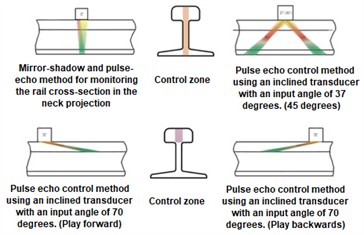
Multi-channel ultrasonic monitoring systems (Fig. 1) - evolution of trolleys with one sensor. They work as scanning devices and create a three-dimensional acoustic representation of the rail cross-section. Their development is due to the different orientation of fatigue cracks: vertical, transverse and inclined (RCF, Fig. 2).
A single probe cannot reliably detect all types of damage; therefore, a set of transducers with different incident angles is used.
Fig. 1Multi-channel inspection scheme and insonification methods. Source: developed by the authors
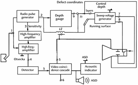
Fig. 2Basic schemes for sounding rails. Source: developed by the authors
2.4. Phased array systems
Phased array systems is an advanced method of ultrasonic rail inspection. They contain 16-128 piezoelectric elements, each of which is individually delayed, allowing wavefront control, unlike conventional fixed-beam transducers. This makes it possible to electronically vary the direction, focal position, and penetration depth of the ultrasonic beam without mechanical movement of the probe. In essence, a single transducer performs the function of an entire array of sensors.
2.5. Eddy current testing
Fatigue cracks during rolling occur in a layer of 1-3 mm (Fig. 3). Ultrasonic testing is ineffective here, so the eddy current method is used: it detects changes in electrical conductivity due to microcracks, rather than the geometry of the defect [5]. The method is sensitive at an early stage - the rail can still be repaired by grinding.
The main limitation of the method is the shallow inspection depth; therefore, it is used in combination with ultrasonic testing.
Fig. 3Ultrasonic rail scan (B-scan). Source: developed by the authors based on ultrasonic inspection principles described in [6-10]
![Ultrasonic rail scan (B-scan). Source: developed by the authors based on ultrasonic inspection principles described in [6-10]](https://static-01.extrica.com/articles/26499/26499-img3.jpg)
2.6. Magnetic testing
Magnetic flux leakage (Fig. 4) is used for high-speed rail inspection. In case of a crack, part of the flow flows out of the magnetized rail. The method reacts to the volume of damaged metal, is effective for transverse defects, but is less sensitive to fine surface cracks [11].
The principal advantage is high inspection speed and independence from the rail surface condition.
Fig. 4Specialized rail inspection vehicle. Source: developed by the authors based on modern rail diagnostic systems described in [11-13]
![Specialized rail inspection vehicle. Source: developed by the authors based on modern rail diagnostic systems described in [11-13]](https://static-01.extrica.com/articles/26499/26499-img4.jpg)
2.7. Acoustic emission
Acoustic emission does not directly detect a defect, but the process of its growth: when a crack spreads, elastic energy is released in the form of wave pulses [12]. Sensors register them – this is how they detect active defects that can lead to failure. The method is valuable for assessing the severity.
2.8. Integrated diagnostic systems
Modern inspection vehicles integrate all of the above methods. Each technique detects a specific stage of defect development, while combined data processing enables assessment of failure risk. In effect, a digital history of crack evolution is created - from initiation to critical size [13]. The vehicles perform a continuous monitoring of hundreds of kilometers of track in one run. Calculation scenarios are being developed to convert flaw detection data into operational solutions [14-15]. The case of a heavy-duty highway is considered: a freight train moves along an all-welded rail section with a given type of rails (Table 1). The most dangerous defect is analyzed – an inclined fatigue crack in the rail head, detected by ultrasound control with a phased array antenna.
Such defects are among the most dangerous because they propagate into the rail cross-section and lead to transverse rail fracture [16, 17].
Table 1Rolling stock type, rail type and defect parameters
Parameter | Value | Parameter | Value | Parameter | Value |
Wagon type | Gondola freight wagon | Rail profile | R65 | Depth | 6 mm |
Axle load | 23.5 tf | Steel grade | E76KhF | Length | 18 mm |
Wheel load | 115 kN | Young’s modulus () | 2.1×10¹¹ Pa | Inclination angle | 25° |
Operating speed | 70 km/h | Poisson’s ratio (\nu) | 0.3 | Location | 4 mm below the running surface |
Traffic intensity | 70 trains/day | Yield strength | 880 MPa | – | – |
– | – | Fracture toughness () | 50 MPa√m | – | – |
3. Results and analysis
The purpose of the calculations is to obtain the relationship between hidden crack size and the time to rail fracture. In the previous section, a specific defect with a depth of 6 mm was considered. A series of calculations is now performed under the same operating conditions (freight train, axle load 23.5 tf, R65 rail), varying only the crack depth shown in Table 2.
Table 2Dependence of defect severity on crack depth
Depth, mm | KI, MPa | Condition | Remaining cycles | Time |
2 | 30 | stable growth | 1.2×10⁶ | ~1.5 years |
3 | 36 | stable | 4.8×10⁵ | ~7 months |
4 | 42 | accelerated growth | 1.6×10⁵ | ~2 months |
5 | 47 | pre-critical | 2.7×10⁴ | ~10 days |
6 | 52 | critical | 950 | ~1–2 hours |
7 | 57 | failure imminent | <100 | minutes |
The critical fracture depth for the R65 rail is assumed to be 10 mm.
The obtained results demonstrate nonlinear crack propagation behavior. At crack depths below 3 mm, defect growth remains stable and controllable. However, when the crack depth exceeds 4-5 mm, accelerated propagation occurs due to the increase in stress intensity factor. At 6 mm, the stress intensity factor exceeds the fracture toughness threshold, resulting in rapid rail failure.
The calculation procedure includes: 1) determination of the stress intensity coefficient; 2) calculation of the crack growth rate (according to the Paris law); 3) calculation of cycles to a critical depth; 4) conversion into working hours. The defect develops non-linearly: it remains safe for a long time, but at a depth of 4-5 mm, growth accelerates. An S-shaped curve is observed: hidden period → accelerated growth → rapid fracture.
4. Discussion of the results
Based on the calculations, operational defect categories can be formulated (Table 3).
This classification converts defectoscopy data into specific maintenance actions.
Most rail fractures occur shortly after the defect is detected, not because of a control error, but because the crack enters the stage of unstable growth. Therefore, it is important to assess not only the size of the defect, but also its severity.
Table 3Maintenance actions depending on crack depth
Crack depth | Decision |
Up to 3 mm | Scheduled monitoring |
3-4 mm | Repeated inspection once per month |
4-5 mm | Speed restriction |
More than 5 mm | Urgent rail replacement |
More than 6 mm | Track closure |
5. Conclusions
The proposed methodology enables transition from periodic rail inspection to predictive risk-based maintenance strategies. The study aims to move from detecting rail defects to assessing their severity. The methods of non-destructive testing are analyzed: eddy current, ultrasonic, magnetic, acoustic emission - each reveals its own stage of damage [18-20]. A calculation system based on fracture mechanics has been developed. The key parameter is the stress intensity coefficient [21-24]. Calculations for the R65 rail (load 23.5 tons) showed that cracks up to 3 mm are safe, but at 5-6 mm the resource drops to hours. A scale of defect severity has been created for selecting maintenance measures (monitoring, speed limitation, replacement). A risk-based approach reduces the likelihood of sudden failure and eliminates premature rail replacement. The technique is applicable in automated diagnostic systems. The developed approach can be integrated into intelligent railway diagnostic systems for automated assessment of defect criticality and residual rail life prediction.
References
-
M. Kaneta, H. Yatsuzuka, and Y. Murakami, “Mechanism of crack growth in lubricated rolling/sliding contact,” ASLE Transactions, Vol. 28, No. 3, pp. 407–414, 1985, https://doi.org/10.1080/05698198508981637
-
M. Molodova, Z. Li, A. Nunez, and R. Dollevoet, “Monitoring the railway infrastructure: detection of surface defects using wavelets,” in 16th International IEEE Conference on Intelligent Transportation Systems, 2013, https://doi.org/10.1109/itsc.2013.6728413
-
M. Kostrzewski and R. Melnik, “Condition monitoring of rail transport systems: a bibliometric performance analysis and systematic literature review,” Sensors, Vol. 21, No. 14, p. 4710, Jul. 2021, https://doi.org/10.3390/s21144710
-
P. Papaelias, C. Roberts, and C. L. Davis, “A review on non-destructive evaluation of rails: State-of-the-art and future development,” Proceedings of the Institution of Mechanical Engineers, Part F: Journal of Rail and Rapid Transit, Vol. 222, No. 4, pp. 367–384, 2008, https://doi.org/10.1243/09544097jrrt209
-
J. W. Park et al., “Rail surface defect detection and analysis using multi-channel eddy current method based algorithm for defect evaluation,” Journal of Nondestructive Evaluation, Vol. 40, No. 3, p. 83, Sep. 2021, https://doi.org/10.1007/s10921-021-00810-9
-
E. V. Torskaya et al., “Rolling contact fatigue damage in welded rail steel joints,” Physical Mesomechanics, Vol. 25, No. 5, pp. 12–25, 2022, https://doi.org/10.55652/1683-805x_2022_25_5_12
-
P. Mutton, J. Cookson, C. Qiu, and D. Welsby, “Microstructural characterisation of rolling contact fatigue damage in flashbutt welds,” Wear, Vol. 366-367, pp. 368–377, 2016, https://doi.org/10.1016/j.wear.2016.03.020
-
S. M. Zakharov and E. V. Torskaya, “Approaches to modeling occurrence of rolling contact fatigue damages in rails,” Vestnik of the Railway Research Institute, Vol. 77, No. 5, pp. 259–268, 2018, https://doi.org/10.21780/2223-9731-2018-77-5-259-268
-
S. Zakharov et al., “Problems with wheel and rail profiles selection and optimization,” Wear, Vol. 265, No. 9-10, pp. 1266–1272, Oct. 2008, https://doi.org/10.1016/j.wear.2008.03.026
-
E. A. Shur, V. M. Fedin, A. I. Borts, Y. V. Ronzhina, and A. I. Fimkin, “Methods of elimination of rails increased damage in the area of weld joints,” Vestnik of the Railway Research Institute, Vol. 78, No. 4, pp. 210–217, 2019, https://doi.org/10.21780/2223-9731-2019-78-4-210-217
-
A. G. Antipov and A. A. Markov, “Detectability of rail defects by magnetic flux leakage method,” Russian Journal of Nondestructive Testing, Vol. 55, No. 4, pp. 277–285, Jun. 2019, https://doi.org/10.1134/s1061830919040028
-
T. M. Roberts and M. Talebzadeh, “Acoustic emission monitoring of fatigue crack propagation,” Journal of Constructional Steel Research, Vol. 59, No. 6, pp. 695–712, Jun. 2003, https://doi.org/10.1016/s0143-974x(02)00064-0
-
A. Jamshidi et al., “A big data analysis approach for rail failure risk assessment,” Risk Analysis, Vol. 37, No. 8, pp. 1495–1507, May 2017, https://doi.org/10.1111/risa.12836
-
X. Jin, Z. Wen, W. Zhang, and Z. Shen, “Numerical simulation of rail corrugation on a curved track,” Computers and Structures, Vol. 83, No. 25-26, pp. 2052–2065, 2005, https://doi.org/10.1016/j.compstruc.2005.03.012
-
J. Xu, P. Wang, Y. Gao, J. Chen, and R. Chen, “Geometry evolution of rail weld irregularity and the effect on wheel-rail dynamic interaction in heavy haul railways,” Engineering Failure Analysis, Vol. 81, pp. 31–44, 2017, https://doi.org/10.1016/j.engfailanal.2017.07.009
-
R. Masoudi Nejad, M. Shariati, and K. Farhangdoost, “Prediction of fatigue crack propagation and fractography of rail steel,” Theoretical and Applied Fracture Mechanics, Vol. 101, pp. 320–331, Jun. 2019, https://doi.org/10.1016/j.tafmec.2019.03.016
-
A. Ekberg and E. Kabo, “Fatigue of railway wheels and rails under rolling contact and thermal loading-an overview,” Wear, Vol. 258, No. 7-8, pp. 1288–1300, Mar. 2005, https://doi.org/10.1016/j.wear.2004.03.039
-
D. J. Batyrova, A. M. Zhangabylova, Z. K. Aymurzaeva, G. O. Sarsenova, and I. S. Bondar, “Vibrodiagnostics and dynamic operation of reinforced concrete sleepers under the influence of moving load,” Vibroengineering Procedia, Vol. 58, pp. 121–131, 2025, https://doi.org/10.21595/vp.2025.24942
-
I. S. Bondar, G. B. Karibaeva, and A. K. Kurbenova, “Vibration diagnostics of transportation structures on railroads,” Vibroengineering Procedia, Vol. 54, pp. 109–115, Apr. 2024, https://doi.org/10.21595/vp.2024.24093
-
A. Akbayeva et al., “Development of safety methods on artificial structures of railway lines,” Eastern-European Journal of Enterprise Technologies, Vol. 6, No. 1 (120), pp. 43–52, Dec. 2022, https://doi.org/10.15587/1729-4061.2022.269964
-
I. S. Bondar, D. T. Aldekeyeva, and Z. K. Ospanova, “Stress-strain states of reinforced concrete spans of a railroad overpass using a spatial finite element model,” Vibroengineering Procedia, Vol. 54, pp. 320–326, Apr. 2024, https://doi.org/10.21595/vp.2024.24086
-
M. Pletz, W. Daves, W. Yao, W. Kubin, and S. Scheriau, “Multi-scale finite element modeling to describe rolling contact fatigue in a wheel-rail test rig,” Tribology International, Vol. 80, pp. 147–155, 2014, https://doi.org/10.1016/j.triboint.2014.07.005
-
I. G. Goryacheva, S. N. Soshenkov, and E. V. Torskaya, “Modelling of wear and fatigue defect formation in wheel-rail contact,” Vehicle System Dynamics, Vol. 51, No. 6, pp. 767–783, 2013, https://doi.org/10.1080/00423114.2011.602419
-
G. Trummer, C. Marte, P. Dietmaier, C. Sommitsch, and K. Six, “Modeling surface rolling contact fatigue crack initiation taking severe plastic shear deformation into account,” Wear, Vol. 352-353, pp. 136–145, Apr. 2016, https://doi.org/10.1016/j.wear.2016.02.008
About this article

The authors have not disclosed any funding.
The authors would like to express their gratitude to NC KTZh JSC, Almaty distance railway department (ТP-46) for the opportunity and assistance in organizing the field studies.
The datasets generated during and/or analyzed during the current study are available from the corresponding author on reasonable request.
The authors declare that they have no conflict of interest.

