Abstract
This research investigates the dynamic stress–strain behavior of a railway bridge beam superstructure subjected to moving train loads using advanced computational modeling. The study employs MIDAS Civil software to develop a comprehensive three-dimensional finite element model of a typical railway bridge superstructure, incorporating realistic boundary conditions, material properties, and geometric configurations. The analysis examines the temporal variation of stresses, displacements, and internal forces as multiple train axles traverse the bridge at various operational speeds. The investigation reveals critical zones experiencing maximum dynamic amplification factors, which significantly exceed those predicted by static analysis methodologies. Dynamic load allowance coefficients are calculated for different train speeds, demonstrating a nonlinear relationship between velocity and structural response amplification. The model accounts for complex phenomena including moving load effects, inertial forces, and structural damping characteristics. Results indicate that dynamic effects become particularly pronounced at specific resonance frequencies, where vertical deflections and bending moments reach peak magnitudes. The findings provide essential insights for bridge design optimization, maintenance planning, and safety assessment protocols. This comprehensive dynamic analysis framework enables engineers to accurately predict structural behavior under realistic operational conditions, ensuring adequate service life and structural integrity of railway bridge infrastructure systems while maintaining required safety margins for contemporary high-speed rail applications.
Highlights
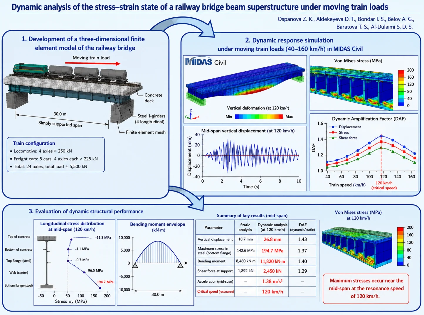
- A three-dimensional finite element model of a simply supported railway bridge was developed in MIDAS Civil to simulate the dynamic response under moving train loads.
- Dynamic amplification factors increased with train speed and reached their maximum values at approximately 120 km/h, where the bridge exhibited resonant behavior with a maximum displacement of 26.8 mm (DAF = 1.43) and a maximum stress of 194.7 MPa (DAF = 1.37).
- The proposed numerical methodology accurately identifies critical stress zones and dynamic effects, providing a reliable tool for the design, safety assessment, and maintenance planning of railway bridge superstructures.
1. Introduction
The infrastructure of railway bridges is a key element of transport networks that ensure the movement of passengers and cargo. With increasing speeds and axle loads, accurate assessment of the dynamic behavior of structures is critically important for the safety and durability of bridges. Traditional static methods do not take into account temporary changes in the reaction of the structure during train movement. Dynamic effects (vibrations, resonance, etc.) lead to stresses and deflections exceeding the calculated static values. The study is devoted to the dynamic analysis of bridge spans by the finite element method using MIDAS Civil software. Tasks: 1) development of a finite element model; 2) assessment of stresses and deformations during train movement; 3) determination of dynamic coefficients and velocity effects; 4) identification of critical stress zones [1].
Dynamic analysis of railway bridges has been actively studied for several decades. Willis and Timoshenko laid the foundations for the dynamic response of beams under moving loads, and Fryba (1999) developed the theoretical foundations for analyzing structural vibrations. Experiments on existing bridges have made it possible to measure dynamic deformations and accelerations, revealing the dependence of the reaction on the characteristics of the train and the structure. Yang et al. (2004) showed that dynamic gain coefficients change with the speed of the train, and critical speeds cause resonance. Modern research (Xia et al., 2018; Zhai et al., 2019) uses 3D models using the finite element method to study the interaction of loads and the path-bridge system. At the same time, a detailed analysis of the stress-strain state of girder superstructures under real train configurations remains an urgent task [2].
2. Materials and methods
The novelty of the research lies in the complex application of the finite element method for the dynamic analysis of railway spans, taking into account real-world operating conditions. Unlike traditional static calculations, the work takes into account temporary changes in the reaction of the structure when trains are moving at high speeds and increased axial loads. The developed finite element model in the MIDAS Civil software makes it possible not only to evaluate stresses and deformations, but also to accurately determine dynamic coefficients and velocity effects. The study identifies areas of critical stress that arise due to vibrations and resonance, which is impossible with a static approach. The results obtained increase the accuracy of forecasting the durability and safety of bridge structures.
Bridge Model Description. The investigation employs a representative railway bridge configuration consisting of a simply-supported steel-concrete composite beam superstructure. The bridge span length measures 30.0 meters, reflecting typical dimensions encountered in operational railway infrastructure (Table 1). The superstructure comprises four longitudinal steel I-beams with a concrete deck slab, connected through shear studs to ensure composite action [3, 6, 7].
Table 1Bridge geometric parameters and material properties [4, 5]
Component | Parameter | Value | Material | Property | Value |
Bridge | Span length | 30.0 m | Steel | Modulus of elasticity () | 210 GPa |
– | Support type | Simply-supported | – | Density () | 7,850 kg/m3 |
Steel I-Beam | Web depth | 800 mm | – | Yield Strength | 355 MPa |
– | Flange width | 300 mm | Concrete | Modulus of Elasticity () | 35 GPa |
– | Number of Beams | 4 | – | Density () | 2,500 kg/m3 |
Concrete Deck | Thickness | 250 mm | – | Compressive Strength | 40 MPa |
– | Width | 12.0 m | – | – | – |
2.1. Finite element modeling in MIDAS Civil
The calculation model was created in the MIDAS Civil 2023 software using the finite element method. Steel I-beams are modeled by 3D elements with 6 degrees of freedom per node; the length of the elements is 0.50 m (60 elements per beam). The concrete floor slab is divided into 1,440 plate elements (0.50×0.50 m cells). The interaction of beams and flooring is determined by rigid connections. Modal analysis determines the frequencies and waveforms through iterations in the subspace. Damping is according to Rayleigh (2.0 % of the critical value). Train load: locomotive (4 axles, 250 kN/axle) and 5 freight wagons (8 axles each, 225 kN/axle). There are 24 axes in total with a total weight of over 5,000 kN [8, 9].
Dynamic analysis uses the Newmark-beta implicit integration method (0.25, 0.50) in 0.005 s increments, which is enough to capture peak responses. The analysis is performed for train speeds from 40 to 160 km/h (in increments of 20 km/h) [10]. The range covers the speeds at which the excitation frequencies are close to the fundamental frequency, hence the peaks of dynamic amplification [11].
Table 2Train load configuration [10]
Component | Axle load (kN) | Number of axles | Total load (kN) |
Locomotive | 250 | 4 | 1,000 |
Freight car (each) | 225 | 4 | 900 |
Total freight cars | 225 | 20 | 4,500 |
Complete train | – | 24 | 5,500 |
3. Results and discussion
The results of the modal analysis showed the dynamic characteristics of the bridge superstructure. The first natural frequency (symmetrical vertical bend) is 4.28 Hz, the second (antisymmetric bend) is 11.64 Hz, and the third (second symmetrical bend) is 17.32 Hz (Table 3). The main mode of transport provides about 78 % of the total structural response under vertical loads from the train [12].
Table 3Natural frequencies and modal characteristics [12]
Mode | Frequency (Hz) | Period (s) | Description |
1 | 4.28 | 0.234 | Symmetric vertical bending |
2 | 11.64 | 0.086 | Antisymmetric vertical bending |
3 | 17.32 | 0.058 | Second symmetric bending |
4 | 23.57 | 0.042 | Torsional mode |
5 | 29.84 | 0.034 | Third symmetric bending |
3.1. Static analysis results
Static analysis provides basic response values at maximum train loads. The maximum vertical displacement is 18.7 mm (L/1604) in the middle of the span. The stress in the lower flange is 142.6 MPa, the bending moment is 8460 kN·m, and the shear force is 1892 kN at the supports (see Table 4) [13].
Table 4Static analysis results summary [13]
Response parameter | Maximum value | Location |
Vertical displacement | 18.7 mm | Mid-span |
Longitudinal stress (steel) | 142.6 MPa | Bottom flange, mid-span |
Longitudinal stress (concrete) | 8.4 MPa | Top deck, mid-span |
Bending moment | 8,460 kN·m | Mid-span |
Shear force | 1,892 kN | 3.0 m from support |
3.2. Dynamic analysis results
The results of the dynamic analysis revealed an increase in the reactions of the structure relative to static forecasts. At a speed of 120 km/h: displacement – 26.8 mm (DAF = 1.43), voltage – 194.7 MPa (DAF = 1.37). The maximum responses are observed at intermediate speeds (about 120 km/h) – close to the resonant conditions (Fig. 1). DAFS vary: for displacements – 1.14-1.43, stresses – 1.11-1.37, shear forces – 1.08-1.29. Fluctuations in the displacement of the average span occur under successive loads (Table 5) [13].
3.3. Stress-strain state analysis
Studying the stress distribution provides insight into the behavior of the structure. At 120 km/h in the average span: longitudinal stresses range from +194.7 MPa (lower steel flange) to –11.8 MPa (upper concrete fiber). The distribution is almost linear (according to Euler-Bernoulli theory). The Von Mises stresses are up to 162.4 MPa (Table 6), and the elastic behavior is below the yield point (Fig. 2) [14].
Fig. 1The dynamics of movement depending on the speed of the train
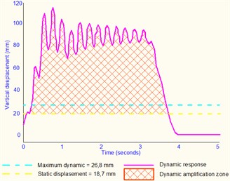
a) Mid-span displacement time history at 120 km/h
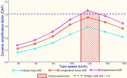
b) Dynamic amplification factors versus train speed
Table 5Dynamic analysis results at various speeds [13]
Speed (km/h) | Max Disp. (mm) | DAF Disp. | Max Stress (MPa) | DAF Stress | Max Accel. (m/s2) |
40 | 21.4 | 1.14 | 158.3 | 1.11 | 0.68 |
60 | 22.1 | 1.18 | 164.0 | 1.15 | 0.85 |
80 | 23.4 | 1.25 | 172.5 | 1.21 | 1.02 |
100 | 25.2 | 1.35 | 186.8 | 1.31 | 1.21 |
120 | 26.8 | 1.43 | 194.7 | 1.37 | 1.38 |
140 | 25.8 | 1.38 | 189.7 | 1.33 | 1.29 |
160 | 24.7 | 1.32 | 182.5 | 1.28 | 1.18 |
Fig. 2Longitudinal stresses and bending moment
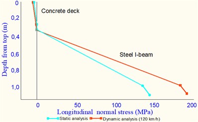
a) Longitudinal stress distribution through depth
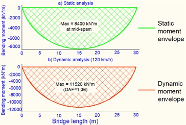
b) Bending moment envelopes
Table 6Stress components at mid-span (120 km/h) [15]
Location | (MPa) | (MPa) | (MPa) |
Concrete top | –11.8 | 0.5 | 11.9 |
Concrete bottom | –1.1 | 1.2 | 2.1 |
Steel top flange | –0.7 | 2.8 | 4.2 |
Steel web center | 96.5 | 18.4 | 103.2 |
Steel bottom flange | 194.7 | 3.2 | 162.4 |
Note: – longitudinal normal stress, – shear stress, – von Mises equivalent stress | |||
3.4. Acceleration response analysis
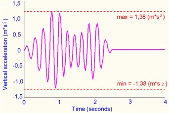
Time diagrams of acceleration show an increase in frequency with increasing train speed. The maximum is 1.38 m/s2 at 120 km/h, which is higher than the forecasts of quasi-static methods. Accelerations affect the path, the interaction of the wheel with the rail, and passenger comfort. The reaction peaks correspond to the passage of the axis groups and the natural frequencies of the structure (Fig. 3) [15].
Fig. 3Vertical acceleration time history at mid-span
4. Conclusions
The study carried out a dynamic analysis of the railway bridge superstructure (finite element method, MIDAS Civil). The effects of dynamic amplification and the relationship between the speed of the train and the behavior of the structure are revealed. Key findings: DAF: 1.14–1.43 (displacements), 1.11-1.37 (stresses) – effects exceed static forecasts; maximum gain – at ~120 km/h (resonance); 3D modeling reflects stress and strain distributions; The coefficients are consistent with the design code. Critical speeds require special attention. Stress data helps to estimate fatigue life and plan maintenance [16-20]. The prospects: analysis of multi-span structures, consideration of the interaction of track and bridge, validation by field measurements.
References
-
L. Fryba, Vibration of Solids and Structures under Moving Loads. Emerald Publishing Limited, 1999, https://doi.org/10.1680/vosasuml.35393
-
Y. B. Yang, J. D. Yau, and Y. S. Wu, Vehicle-Bridge Interaction Dynamics. WORLD SCIENTIFIC, 2004, https://doi.org/10.1142/5541
-
“Eurocode 1: actions on structures – part 2: traffic loads on bridges,” European Committee for Standardization, 2003.
-
H. Xia, N. Zhang, and W. Guo, “Dynamic interaction of train-bridge systems in high-speed railways,” in Advances in High-Speed Rail Technology, Berlin, Heidelberg: Springer Berlin Heidelberg, 2018, https://doi.org/10.1007/978-3-662-54871-4
-
W. Zhai, Z. Han, Z. Chen, L. Ling, and S. Zhu, “Train-track-bridge dynamic interaction: a state-of-the-art review,” Vehicle System Dynamics, Vol. 57, No. 7, pp. 984–1027, 2019, https://doi.org/10.1080/00423114.2019.1605085
-
M. Majka and M. Hartnett, “Effects of speed, load and damping on the dynamic response of railway bridges and vehicles,” Computers and Structures, Vol. 86, No. 6, pp. 556–572, 2008, https://doi.org/10.1016/j.compstruc.2007.05.002
-
K. Liu, G. de Roeck, and G. Lombaert, “The effect of dynamic train-bridge interaction on the bridge response during a train passage,” Journal of Sound and Vibration, Vol. 325, No. 1-2, pp. 240–251, 2009, https://doi.org/10.1016/j.jsv.2009.03.021
-
A. Zangeneh, C. Svedholm, A. Andersson, C. Pacoste, and R. Karoumi, “Identification of soil-structure interaction effect in a portal frame railway bridge through full-scale dynamic testing,” Engineering Structures, Vol. 159, pp. 299–309, Mar. 2018, https://doi.org/10.1016/j.engstruct.2018.01.014
-
J. Oliva, J. M. Goicolea, P. Antolín, and M. Astiz, “Relevance of a complete road surface description in vehicle-bridge interaction dynamics,” Engineering Structures, Vol. 56, pp. 466–476, 2013, https://doi.org/10.1016/j.engstruct.2013.05.029
-
Z. Zhu et al., “Dynamic effect of heavy-haul train on seismic response of railway cable-stayed bridge,” Journal of Central South University, 2023.
-
N. Dinh, K. D. Kim, and P. Warnitchai, “Dynamic analysis of three-dimensional bridge-high-speed train interactions using a wheel-rail contact model,” Engineering Structures, Vol. 31, No. 12, pp. 3090–3106, 2009, https://doi.org/10.1016/j.engstruct.2009.08.015
-
K. Nguyen et al., “Dynamic analysis of high-speed railway traffic loads on ballasted track,” Proceedings of the Institution of Civil Engineers – Transport, 2012.
-
Q. Li, Y. L. Xu, D. J. Wu, and Z. W. Chen, “Computer-aided nonlinear vehicle-bridge interaction analysis,” Journal of Vibration and Control, Vol. 16, No. 12, pp. 1791–1816, Apr. 2010, https://doi.org/10.1177/1077546309341603
-
A. K. Chopra, Dynamics of Structures: Theory and Applications to Earthquake Engineering. Pearson, 2017.
-
“MIDAS civil analysis reference.” MIDAS IT. midasuser.com (accessed 2023).
-
I. S. Bondar, G. B. Karibaeva, and A. K. Kurbenova, “Vibration diagnostics of transportation structures on railroads,” Vibroengineering Procedia, Vol. 54, pp. 109–115, Apr. 2024, https://doi.org/https://doi.org/10.21595/vp.2024.24093
-
A. Akbayeva et al., “Development of safety methods on artificial structures of railway lines,” Eastern-European Journal of Enterprise Technologies, Vol. 6, No. 1 (120), pp. 43–52, Dec. 2022, https://doi.org/10.15587/1729-4061.2022.269964
-
I. S. Bondar, D. T. Aldekeyeva, and Z. K. Ospanova, “Stress-strain states of reinforced concrete spans of a railroad overpass using a spatial finite element model,” Vibroengineering Procedia, Vol. 54, pp. 320–326, Apr. 2024, https://doi.org/10.21595/vp.2024.24086
-
I. Bondar, S. Abdullayev, A. Tursynbayeva, A. Abdullayeva, Y. Auyesbayev, and A. Izbairova, “Identifying the stress-strain state of railroad overpass spans,” Eastern-European Journal of Enterprise Technologies, Vol. 3, No. 7 (135), pp. 14–28, Jun. 2025, https://doi.org/10.15587/1729-4061.2025.327147
-
I. Bondar et al., “Expansion joints and the interface zone of road pavement on bridges and overpasses,” Vibroengineering Procedia, Vol. 60, pp. 54–60, Nov. 2025, https://doi.org/10.21595/vp.2025.25183
About this article

The authors have not disclosed any funding.
The authors would like to express their gratitude to NC KTZh JSC.
The datasets generated during and/or analyzed during the current study are available from the corresponding author on reasonable request.
The authors declare that they have no conflict of interest.

