Abstract
The dynamic effect of the moving load on the bridge construction is the subject of the solution in this article. The bridge is modeled as two span continuous beam with two degrees of freedom. The assumption describing the dynamic deflection curve and the assumption describing the load distribution on individual lumped masses are adopted at the creation of bridge computational model. The plane computational model of heavy vehicle with five degrees of freedom is adopted. The problem is described by ordinary differential equations which are solved numerically by using MATLAB. The results are presented by graphical and numerical form.
1. Introduction
The problems of vehicle bridge interaction belongs to the oldest solved problems of structural dynamics. The works of the civil engineer R. Willis [1] and mathematician G. G. Stoks [2] in which they tried to clarify the breakdown of Chester Rail Bridge in England in 1847 are not only considered the first attempts to solve the problems of vehicle runway interaction but also the first works in the field of structural dynamics. Slovak and Czech Republic are world-known by the high level of bridge engineering and theoretical approach to the solution of dynamical problems of bridges. Basic knowledge concerning of the dynamic investigation of highway and railway bridges was published in monographs [3, 4]. Numerical methods offer an effective tool for the solution of this problem. Current state of computers enables to solve all the problems in real time. The results obtained from numerical analyses are used in the process of the design of optimal parameters of bridges with respect to its lifetime and reliability.
2. Computational vehicle and bridge model
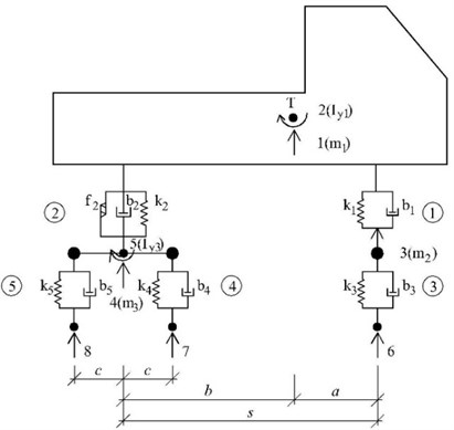
This contribution works with half planar computational model of the lorry Tatra 815, Fig. 1. Equations of motion for 5 unknown functions describing the vehicle vibration are derived as ordinary differential Eq. (1), [5]:
The contact forces ( 6, 7, 8) belong to individual contact points [5] are expressed as:
In the above equations represents the deformation of joining elements, , , are stiffness, damping, mass characteristics and is gravity force. The dot above the symbol marks the derivative with respect to time .
Fig. 1Planar vehicle computational model
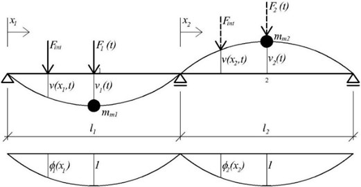
For the bridge the beam computational model with two degrees of freedom was adopted. The shape of deflection curve in time moment and load distribution function were adopted in the computation as sine function, Fig. 2.
Fig. 2Beam computational model of a bridge with two degrees of freedom and load distribution function
Than by the [6]:
where:
Equations of motion can be written as:
In the above expressions is time coordinate, length coordinate, deformation of joining elements, , road roughness, speed of vehicle motion in [m/s], angular frequency, damping angular frequency. Derivations of functions with respect to time are denoted by dot above the symbol.
3. Numerical solution
For the numerical simulation of vehicle motion along the bridge structure the computer program in the program language MATLAB was created. The following input data for vehicle TATRA 815 and for the bridge were used during computation.
Vehicle input data and initial conditions: 287433 N/m, 1522512 N/m, 2550600 N/m, 5022720 N/m, 19228 kg/s, 260197 kg/s, 2746 kg/s, 5494 kg/s, 22950 kg, 910 kg, 2140 kg, 62298 kg∙m2, 932 kg∙m2, 3.135 m, 1.075 m, 4.210 m, 0.660 m, –0.02 m, 0.0 m/s, 0.00 rad, 0.0 rad/s, –0.002 m, 0.0 m/s, –0.003 m, 0.0 m/s, 0.00 rad, 0.0 rad/s.
Bridge input data and initial conditions: 19680.0 kg/m, 1.60622 m4, 3.85e10 N/m2, 0.1 rad/s, 285360.0 kg, 29.0 m, 285360.0 kg, 29.0 m, 0.0 m, 0.0 m/s, 0.0 m, 0.0 m/s.
The results of the numerical simulation are the time course of the vehicle and bridge vibration in graphical or numerical form. For the vehicle the time courses of the displacement components of characteristic points, corresponding the individual degrees of freedom, can be displayed. For the bridge the time courses of vertical mid span deflections of the individual bridge spans can be displayed. It is possible to change vehicle and bridge parameters, initial conditions and vehicle speed. The road profile can be smooth or a random variable.
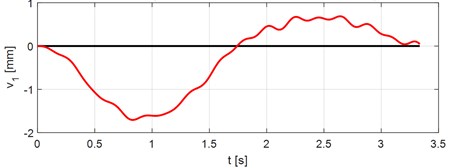
As an example of possible outputs the time courses of bridge and vehicle vibration while the lorry Tatra 815 passes the bridge at the speed 70 km/h along smooth road surface are presented. Fig. 3 and 4 show the time courses of vertical deflections in the middle of the 1st and 2nd spans.
Fig. 3Vertical bridge deflection in the middle of the 1st span. Vehicle speed V= 70 km/h
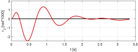
In Fig. 5 the time course of vertical deflection of the vehicle sprung mass gravitational center is displayed. In Fig. 6 the time course of rotation of the vehicle sprung mass is displayed.
Fig. 4Vertical bridge deflection in the middle of the 2nd span. Vehicle speed V= 70 km/h
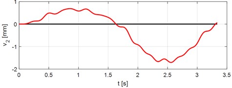
Fig. 5Vertical deflection of the vehicle sprung mass gravitational center. Vehicle speed V= 70 km/h
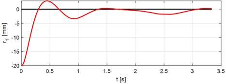
Fig. 6Rotation of the vehicle sprung mass. Vehicle speed V= 70 km/h
4. Conclusions
Numerical modeling of the problems of vehicle and bridge interaction is an effective tool for the solution of real tasks of engineering practice. It allows numerically to obtain results that were previously obtained only by experimental test on the finished structure. Quality of obtained results is dependent on the quality of input data. Current state of computers enables the numerical processing of solved problems in real time. From the practical point of view the influence of various vehicle and bridge parameters is interested. The results obtained from numerical analyses are used in the process of design of optimal bridge parameters with respect to lifetime and reliability of the bridge structure.
References
-
Willis R. Report of the Commissioners Appointed to Inquire into the Application of Iron to Railway Structures. Stationary Office, London, 1849.
-
Stokes G. G. Discussion of a differential equation relating to the breaking of railway bridges. Transactions Cambridge Philosophic Society, Vol. 8, 1849, p. 707-220.
-
Melcer J. Dynamic Computation of Highway Bridges. Edis, University of Žilina, Žilina, 1997, (in Slovak).
-
Frýba L. Dynamics of Railway Bridges. Academia, Prague, 1992, (in Czech).
-
Kuchárová D., Lajčáková G. Modelling of moving load effect on concrete pavements. MATEC Web of Conferences, 2017.
-
Melcer J. Experimental verification of a computing model. Applied Mechanics and Materials, Vol. 732, 2015, p. 345-348.
About this article

