Abstract
Rubber stern tube bearings are critical to marine propulsion systems; however, friction-induced vibration may arise under conditions of low rotational speed, high load, localized heating, and inadequate lubrication. To characterize the dynamic behavior of the bearing–shaft system, a series of controlled experiments was conducted by varying the load pressure, thermal conditions, and rotational speed. Time- and frequency-domain responses, together with shaft orbit measurements, were analyzed to identify friction-related signatures. The results indicate that time-domain responses exhibit pulse-like features, while the spectra contain pronounced components at the fundamental and higher-order harmonic frequencies. Concurrently, the shaft orbits deviate from regular elliptical trajectories, exhibiting irregular geometries with angular distortions. The consistent features observed across the temporal, spectral, and orbital domains provide complementary indicators of friction-induced vibration. These findings demonstrate the potential of multi-domain response analysis for diagnosing friction-related anomalies in marine bearings.
1. Introduction
The stern tube bearing is a critical component of marine propulsion shafting, with rubber being one of the most widely used materials for water-lubricated bearings [1]. Owing to its inherent damping capacity, rubber can effectively attenuate shaft vibration and associated structural responses. However, under unfavorable lubrication conditions, particularly at low rotational speeds, high loads, elevated temperatures, and during start-up or shutdown, the lubrication film may become insufficient to separate the shaft and bearing surfaces. Under such conditions, direct contact and friction may occur at the bearing interface, resulting in friction-induced vibration and noise and potentially degrading the dynamic performance of the propulsion system [2-3].
Research on the friction and vibration mechanisms of rubber bearings dates back to the 1970s, when early studies focused primarily on identifying the critical conditions associated with abnormal vibration and noise [4]. Since then, various theoretical and numerical approaches have been developed to investigate friction-induced instability in marine shafting systems. These approaches can be broadly classified into three categories: phenomenological modeling, linear stability analysis, and transient dynamic analysis. Phenomenological models generally employ low-dimensional mass-spring systems coupled with simplified frictional contact elements [5-6]. Despite their simplicity, these models are particularly useful for identifying the fundamental mechanisms responsible for self-excited vibration, including stick-slip motion, velocity-dependent friction characteristics. However, their simplified representation of the structural dynamics and frictional interface limits their ability to reproduce the complex dynamic behavior of practical shafting systems. Linear stability analysis provides an alternative framework by evaluating the complex eigenvalues and eigenmodes of the coupled system around a quasi-static equilibrium state obtained from nonlinear contact analysis [7]. This approach enables efficient identification of instability onset and facilitates parametric investigations of systems with realistic structural components.
Transient dynamic analysis based on direct numerical integration can overcome some of these limitations by explicitly resolving the temporal evolution of nonlinear contact and frictional interactions [8-9]. Such approaches can capture the amplitude, waveform, and transient development of friction-induced oscillations and have been employed to examine the effects of friction laws and structural dynamics on system instability [10]. However, the high computational cost associated with long-time integration and nonlinear contact calculations can limit their direct application to practical engineering systems.
More recently, continuous and high-fidelity models of marine shafting systems incorporating interfacial friction have been developed to investigate friction-induced instability and the resulting nonlinear dynamics [11-13]. These studies have considered the interactions between friction and multiple vibration components, including shaft torsional vibration, tangential vibration of water-lubricated rubber bearings, torsional–lateral coupling. Such coupled models provide a more realistic representation of the dynamic interactions within marine propulsion shafting and offer further insight into the mechanisms underlying friction-induced instability.
Despite these advances, previous studies have largely focused on the mechanisms and influencing factors of friction-induced instability, whereas the experimentally observable vibration characteristics of the shaft and bearing housing remain insufficiently characterized. In particular, because friction originates from localized contact at the shaft-bearing interface, the shaft vibration state provides an important dynamic signature of the evolving frictional condition. A systematic characterization of these signatures is therefore essential for linking the underlying frictional interaction to experimentally measurable responses and for developing practical diagnostic approaches. In this study, an experimental investigation is conducted using a dedicated test rig for water-lubricated rubber stern tube bearings. The effects of operating conditions associated with frictional contact are systematically investigated, and the corresponding dynamic responses of the bearing-shaft system are characterized in the time, frequency, and shaft-orbit domains. The vibration signatures under frictional conditions are compared with those under normal operating conditions to identify characteristic features associated with abnormal friction. The results provide experimental insight into the dynamic response of water-lubricated stern tube bearings under frictional conditions and establish a basis for vibration-based identification of friction-related anomalies in marine propulsion shafting.
2. Test platform
The experiments were conducted using a water-lubricated stern tube bearing test rig, as shown in Fig. 1. The test rig consists of an electric motor, cooling system, supporting bearing, stern tube bearing, hydraulic loading system, and data acquisition system. The test shaft is manufactured from 45 steel and fitted with a ZQSn10-2 sleeve with a length of 175 mm and an outer diameter of 150 mm. The supporting bearing is a sliding bearing. A vertical load is applied at the midpoint of the bearing through a hydraulic cylinder to achieve a relatively uniform bearing pressure along the bearing length. The measurement system comprises a torque-speed meter, pressure gauge, vibration and displacement sensors, and a data acquisition unit. The torque-speed meter records the rotational speed and friction torque of the test shaft, while the pressure gauge monitors the hydraulic loading pressure. Force sensors are employed to measure the load transmitted to the stern tube bearing. The vibration and displacement sensors are used to characterize the dynamic response of the bearing–shaft system under different operating conditions.
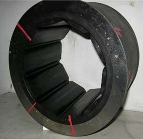
The tested rubber stern tube bearing has an inner diameter of 152 mm and a length of 150 mm. It is equipped with 10 cooling grooves, each 8 mm in depth, to facilitate water circulation and heat dissipation during operation. Two accelerometers are mounted on the bearing housing to measure the vibration response, while a pair of orthogonally arranged displacement sensors is installed behind the bearing to monitor the shaft center motion and obtain the shaft orbit. The physical configuration of the rubber stern tube bearing are illustrated in Fig. 2.
Fig. 1Test platform of a shafting system supported by a water-lubricated bearing: 1. Main shaft; 2. Support bearing; 3. Vertical loading hydraulic cylinder; 4. Test bearing housing; 5. Stern tube bearing; 6. Sealing device; 7. Hydrostatic spherical bearing; 8. Torque and speed transducer; 9. Support bearing; 10. Variable frequency motor; 11. Speed sensor
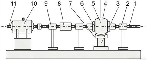
Fig. 2Physical model of a rubber bearing
3. Mathematical model
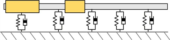
Fig. 3 illustrates a schematic representation of the test platform and its corresponding dynamic model. The shaft is modeled using Timoshenko beam elements, while the propeller and other attached components are represented by lumped inertial elements. The water-lubricated bearings and coupling are modeled as linear spring-damper elements characterized by equivalent stiffness and damping coefficients. The foundation is assumed to be rigid. Accordingly, the interaction forces acting on the shaft can be expressed in the following generalized form:
Fig. 3Schematic model of test platform
The dynamic model of the shafting system is constructed by using the finite element method (FEM) through discretization of virtual variations of strain and kinetic energies:
where, represents the nonlinear contact loads at the bearing-shaft interface. , and , respectively, denote the mass, damping and stiffness matrices composed by the attachments. The governing equation of the shafting system can be finally derived by assembling Eqs. (1) and (2) for all the beam elements and attachments as follows:
where is the displacement vector, , and denote the mass, damping and stiffness matrices of the shaft. refers to the external force vector and is the nonlinear load occurring at the bearing/shaft interfaces. When the shaft rotates and encounters with lateral deflections, the bearing-shaft contact also induces the tangential frictional contact force and torque. From the Coulomb’s law of friction, the friction force and torque arising from the contact are defined as:
where is a dynamic friction coefficient depended on the relative sliding velocity between the shaft and bearing at the contact point. An exponential model that can effectively characterize the apparent velocity-weakening effect observed in the experiments is adopted:
The relative sliding speed at the contact nodes can be explicitly described by contributions from the rotational speed , the whirl motion and torsional deformation of the shaft, and the tangential vibrations of the bearing:
where and are the torsional deformation of the shaft and the tangential vibrational displacement of bearing, respectively.
4. Test process and results
The bearing load is controlled by hydraulic loading applied at the bearing seat, while the bearing temperature is regulated through the cooling-water system. After the bearing pressure and cooling-water temperature are prescribed, the shaft is gradually decelerated from a high rotational speed until friction-induced vibration is initiated. Under the frictional condition, pronounced stick–slip motion can be observed at the shaft-bearing interface. The vibration responses under both normal and frictional operating conditions are recorded for subsequent comparison and analysis. The corresponding experimental results are presented and discussed below:
4.1. Time domain characteristics of vibration signals
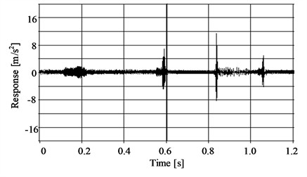
Under normal operating conditions, the vibration response measured at the bearing housing remains relatively stable, with limited amplitude variation. In contrast, the onset of abnormal friction results in pronounced temporal fluctuations in the vibration amplitude. The signal exhibits alternating high- and low-amplitude intervals, accompanied by distinct pulsations and strong periodic characteristics. Figs. 4-6 compare the time-domain vibration responses under normal and abnormal friction conditions. At a rotational speed of 100 r/min, the vibration acceleration under abnormal friction reaches approximately 12 m/s2, which is roughly15 times higher than that observed under normal operating conditions. This substantial increase in amplitude indicates a significant alteration in the dynamic response of the bearing–shaft system associated with the onset of frictional interaction.
Analysis suggests that the observed pulses are associated with intermittent frictional contact at the stern tube bearing. Depending on the severity and spatial distribution of the frictional interaction, one or more contact events may occur during each shaft revolution, resulting in one or multiple pulses in the time-domain vibration signal. Consequently, the pulse sequence exhibits a distinct periodicity related to the shaft rotational period. A comparison of the vibration responses in Figs. 5 and 6 further demonstrates that the frictional interaction in Fig. 6 is more severe than that in Fig. 5, as evidenced by the increased pulse density and the shorter intervals between successive pulses.
Fig. 4Normal vibration (100 r/min, 30 ℃, 0.3 MPa)
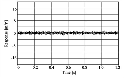
Fig. 5Friction vibration (33 r/min, 30 ℃, 0.3 MPa)
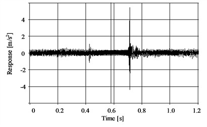
Fig. 6Friction vibration (42 r/min, 40 ℃, 0.4 MPa)
4.2. Spectral characteristics of vibration signals
When abnormal friction develops at the shaft-stern tube bearing interface, the nonlinear frictional interaction generates complex vibration responses in both the shaft and bearing housing. The corresponding spectra contain a broad range of frequency components, including low-frequency components associated with the inherent dynamics of the shaft-bearing system and high-frequency components well above the shaft rotational frequency.
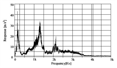
Under normal operating conditions, the dominant vibration energy is concentrated below 1 kHz, exhibiting pronounced spectral peaks at 134 Hz and 249 Hz. As shown in Fig. 7, the 249 Hz component is associated with periodic excitation generated by the hydraulic loading system and primarily reflects the inherent dynamic characteristics of the shaft supported by the stern tube bearing.In contrast, under abnormal friction conditions, the spectral amplitude increases substantially, and additional high-frequency components emerge alongside the low-frequency components associated with shaft dynamics. A prominent spectral peak is observed at approximately 1.25 kHz, accompanied by harmonic components near twice the fundamental frequency, as illustrated in Fig. 8. Notably, while the characteristic peak frequency remains relatively stable across different friction conditions, its amplitude increases progressively with friction severity. This frequency-invariant but amplitude-dependent behavior suggests that the 1.25 kHz component serves as a potential spectral indicator for characterizing the severity of friction-induced vibration. The occurrence of abnormal friction between the shaft and the stern tube bearing introduces nonlinear characteristics, inducing complex vibration signals in both components. Consequently, the spectral signal exhibits rich features, comprising not only low-frequency components reflecting the vibration characteristics of the shaft system but also high-frequency components significantly exceeding the shaft frequency.
The experimentally observed vibration characteristics can be explained by the above dynamic model. According to Eqs. (4)-(6), the friction force and torque are governed by both the normal contact load and the relative sliding velocity at the shaft–bearing interface. The latter is not determined solely by the shaft rotational speed, but is jointly affected by shaft rotation, lateral whirling motion, torsional deformation, and tangential vibration of the bearing. Consequently, the relative sliding velocity continuously fluctuates during operation, leading to a time-varying friction force and torque. In particular, the adopted velocity-dependent friction law exhibits a velocity-weakening characteristic, i.e., the friction coefficient decreases with increasing sliding velocity. Such a negative friction–velocity dependence can reduce the effective damping of the shaft–bearing system and, under appropriate operating conditions, provide energy to the structural vibration, thereby promoting friction-induced self-excited oscillations. When the shaft repeatedly enters and leaves local contact regions during rotation, the resulting intermittent frictional interactions generate periodic pulses in the time-domain response. The nonlinear dependence of the friction force on the relative velocity further modulates these pulses, introducing harmonic and higher-frequency components into the vibration spectrum. This spectral broadening is a direct consequence of the nonlinear stiffness and damping characteristics introduced by the friction contact. As the frictional interaction becomes more severe, the magnitude of the friction force and the associated energy transfer increase. This leads primarily to a substantial rise in vibration amplitude, while the dominant characteristic frequencies remain largely governed by the inherent dynamic properties (natural frequencies) of the shaft–bearing system. However, the emergence of high-frequency components suggests that the friction excitation is sufficiently broadband to activate higher-order structural modes. This mechanism is consistent with the experimentally observed transition from stable, low-amplitude responses under normal conditions to pronounced pulsating and high-frequency vibration under abnormal friction, confirming that the instability is driven by the interplay between the velocity-weakening friction law and the structural dynamics.
Fig. 7Normal vibration (100 r/min)
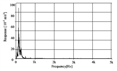
Fig. 8Friction vibration (42 r/min, 40 ℃, 0.4 MPa)
4.3. Shaft orbit
The shaft center orbit describes the trajectory of the shaft center relative to the bearing housing and provides a direct representation of the instantaneous whirling motion of the shaft. Both the orbit amplitude and geometric characteristics, including its shape, eccentricity, and distortion, provide valuable information on the dynamic state of the shaft-bearing system and can be used to identify abnormal operating conditions. In the present study, the shaft orbit is reconstructed from the displacement measurements in two orthogonal directions. The radial displacement, defined as the instantaneous distance between the shaft center and the bearing center, is expressed as:
And the phase angle (azimuth angle of shaft center) refers to Eq. (8):
where is real-time displacement in -direction from eddy current sensor, is real-time displacement in -direction from eddy current sensor.
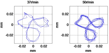
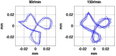
Fig. 9 compares the shaft center orbits at different rotational speeds under a specific bearing pressure of 0.3 MPa. Owing to the relatively compact dimensions and structural constraints of the test rig, the shaft orbit exhibits distinct local impact and rebound features, resulting in a characteristic petal-like trajectory. These localized distortions are attributed to intermittent shaft-bearing contact during whirling. As described by Eqs. (4-6), the relative sliding velocity at the contact interface is jointly determined by shaft rotation, lateral whirling, torsional deformation, and tangential bearing vibration. The resulting friction force therefore varies continuously with the instantaneous contact state, producing repeated frictional excitation and local changes in the shaft trajectory. At lower rotational speeds, the relative sliding velocity is relatively small and the shaft is more susceptible to intermittent contact, leading to stronger orbit distortion and poorer repeatability. With increasing rotational speed, the shaft motion becomes more dominated by continuous rotational and whirling components, while the relative sliding velocity increases and the intermittent contact becomes comparatively less pronounced. Consequently, the shaft orbit becomes more repeatable, with smoother local corners and reduced geometric distortion.
Fig. 9Shaft orbit for different rotating speeds
4.4. Effects of non-uniform load on shaft orbits
The experiment was primarily conducted to investigate the vibration and noise characteristics of the rubber stern tube bearing under non-uniformly distributed bearing loads. The cooling-water temperature was maintained at 30 °C with a flow rate of 12.5 L/min. For the uniformly loaded condition, the hydraulic loading point was located at the center of the bearing housing, whereas for the non-uniformly loaded condition, the loading point was shifted approximately 40 mm from the bearing center.
Fig. 10 compares the shaft center orbits under the two loading conditions. Although the nominal bearing load is maintained at a constant level, the non-uniform loading condition induces pronounced deformation of the shaft orbit, particularly at low rotational speeds. The orbit exhibits sharp corners, localized distortions, and reduced repeatability, indicating intensified intermittent contact between the shaft and the bearing. This behavior is attributed to the redistribution of contact pressure along the bearing length caused by the eccentric loading position. The resulting local increase in contact pressure promotes localized friction and intermittent stick–slip interactions. Furthermore, at low rotational speeds, the relative sliding velocity is relatively small, rendering the shaft–bearing interface more susceptible to boundary-contact conditions and friction-induced instability. Consequently, the friction force varies significantly with the instantaneous shaft position and relative velocity, leading to enhanced nonlinear excitation and substantial distortion of the shaft orbit. From a mechanistic standpoint, the sharp corners observed in the shaft orbit correspond to abrupt transitions between the stick and slip phases of the friction cycle. During the stick phase, the friction force exceeds the restoring force of the shaft, effectively constraining the shaft center and causing the orbit to stall at a localized region. Once the accumulated elastic energy in the shaft overcomes the static friction threshold, a rapid slip event is triggered, producing the sharp directional change visible in the orbit trajectory. These observations demonstrate that the spatial distribution of the bearing load, rather than merely its nominal magnitude, plays a critical role in determining the dynamic response of the shaft–bearing system.
Fig. 10Shaft orbit for different loading cases
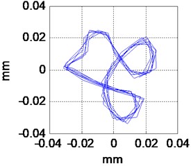
a) Uniform load, 0.2 MPa
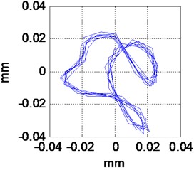
b) Non-uniform load, 0.2 MPa
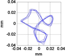
c) Uniform load, 0.3 MPa
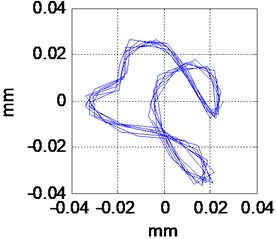
d) Non-uniform load, 0.3 MPa
5. Conclusions
The theoretical model and experimental investigations provide consistent evidence of the dynamic mechanisms underlying friction-induced vibration in water-lubricated rubber stern tube bearings. The theoretical friction model indicates that the friction force is governed by the instantaneous normal contact load and the relative sliding velocity at the shaft-bearing interface. Since the relative velocity is coupled with shaft rotation, whirling motion, torsional deformation, and bearing vibration, the friction force acts as a nonlinear excitation. The velocity-dependent friction law can further reduce the effective damping of the system and promote self-excited oscillations under unfavorable operating conditions. This mechanism is consistent with the experimentally observed pulsating time-domain responses, additional harmonic and high-frequency spectral components, and distorted shaft center orbits. In particular, intermittent contact and stick–slip interactions at low rotational speeds produce pronounced local distortions and sharp corners in the shaft orbit, while increasing friction severity primarily leads to an increase in vibration amplitude rather than a significant shift in the characteristic frequencies.
The experiments further demonstrate that the dynamic response is strongly influenced by both rotational speed and the spatial distribution of the bearing load. Under abnormal friction, the bearing-housing vibration exhibits periodic pulses associated with intermittent frictional contact, and the pulse density and vibration amplitude increase with friction severity. Meanwhile, characteristic high-frequency components emerge in the vibration spectrum, providing additional signatures for friction identification. Non-uniform loading, even when the nominal bearing load is maintained constant, results in more severe orbit distortion, higher bearing-housing vibration, and a higher critical rotational speed for the onset of friction-induced vibration compared to uniform loading. These results indicate that the combined analysis of time-domain, frequency-domain, and shaft-orbit characteristics offers complementary indicators for identifying friction-related anomalies. Furthermore, the findings highlight the critical importance of considering the actual spatial distribution of bearing loads and nonlinear frictional interactions in the vibration assessment and low-noise design of marine propulsion shafting.
References
-
R. L. Orndorff Jr, “Water-lubricated rubber bearings, history and new developments,” Naval Engineers Journal, Vol. 97, No. 7, pp. 39–52, 1985, https://doi.org/10.1111/j.1559-3584.1985.tb01877.x
-
W. Litwin, “Influence of main design parameters of ship propeller shaft water-lubricated bearings on their properties,” Polish Maritime Research, Vol. 17, No. 4, pp. 39–45, Jan. 2010, https://doi.org/10.2478/v10012-010-0034-z
-
Z. Zhang et al., “Review of the evolution and prevention of friction, wear, and noise for water-lubricated bearings used in ships,” Friction, Vol. 12, No. 1, pp. 1–38, Mar. 2023, https://doi.org/10.1007/s40544-022-0707-5
-
H. Hirani and M. Verma, “Tribological study of elastomeric bearings for marine propeller shaft system,” Tribology International, Vol. 42, No. 2, pp. 378–390, Sep. 2008, https://doi.org/10.1016/j.triboint.2008.07.014
-
R. A. Ibrahim, “Friction-induced vibration, chatter, squeal, and chaos-part I: mechanics of contact and friction,” Applied Mechanics Reviews, Vol. 47, No. 7, pp. 209–226, 1994, https://doi.org/10.1115/1.3111079
-
Z. Xie, J. Li, Y. Tian, P. Du, B. Zhao, and F. Xu, “Theoretical and experimental study on influences of surface texture on lubrication performance of a novel bearing,” Tribology International, Vol. 193, p. 109351, Feb. 2024, https://doi.org/10.1016/j.triboint.2024.109351
-
T. A. Simpson and R. A. Ibrahim, “Nonlinear friction-induced vibration in water-lubricated bearings,” Journal of Vibration and Control, Vol. 2, No. 1, pp. 87–113, Jan. 1996, https://doi.org/10.1177/107754639600200106
-
X. Guo et al., “Friction-induced vibration in ship water-lubricated bearings: a review,” Lubricants, Vol. 14, No. 3, p. 107, Feb. 2026, https://doi.org/10.3390/lubricants14030107
-
Z. Zhang, Z. Zhang, X. Huang, and H. Hua, “Stability and transient dynamics of a propeller-shaft system as induced by nonlinear friction acting on bearing-shaft contact interface,” Journal of Sound and Vibration, Vol. 333, No. 12, pp. 2608–2630, 2014, https://doi.org/10.1016/j.jsv.2014.01.026
-
X. Zhou, F. Kuang, J. Huang, X. Liu, and K. Gryllias, “Water-lubricated stern bearing rubber layer construction and material parameters: effects on frictional vibration based on computer vision,” Tribology Transactions, Vol. 64, No. 1, pp. 65–81, Jan. 2021, https://doi.org/10.1080/10402004.2020.1803463
-
F. Kuang, X. Zhou, J. Huang, H. Wang, and P. Zheng, “Machine-vision-based assessment of frictional vibration in water-lubricated rubber stern bearings,” Wear, Vol. 426-427, No. Part A, pp. 760–769, Apr. 2019, https://doi.org/10.1016/j.wear.2019.01.087
-
Q. Huang, H. Liu, and Z. Ding, “Dynamical response of the shaft-bearing system of marine propeller shaft with velocity-dependent friction,” Ocean Engineering, Vol. 189, p. 106399, Sep. 2019, https://doi.org/10.1016/j.oceaneng.2019.106399
-
Z. Zhang, N. Duan, C. Lin, and H. Hua, “Coupled dynamic analysis of a heavily-loaded propulsion shafting system with continuous bearing-shaft friction,” International Journal of Mechanical Sciences, Vol. 172, p. 105431, Jan. 2020, https://doi.org/10.1016/j.ijmecsci.2020.105431
About this article

The authors have not disclosed any funding.
The datasets generated during and/or analyzed during the current study are available from the corresponding author on reasonable request.
The authors declare that they have no conflict of interest.

