Abstract
An analytical-numerical model is developed for the variable-section shaft of a modernized hydro-friction torsion damper for high-speed electric rolling stock. The spatial coefficients are derived explicitly from line mass , flexural rigidity , and separate restoring and rotational terms. The source model uses 100 sections, piecewise-linear approximation, Fourier separation and a one-sided Laplace transform. A variable-coefficient benchmark with 50-400 Hermite elements verifies the spatial discretization: at 100 elements the curvature-energy and bending-moment errors are 0.00368 % and 0.00822 %, or 0.00529 % and 0.01234 % with linearly interpolated properties. These results verify the benchmark, not the complete damper model. Field observations of 3-5 Hz horizontal and 7-12 Hz vertical vibrations and piston velocities up to 520/580 mm/s are used only as operating context because calibrated transmitted loads and shaft-strain histories are unavailable. No unsupported stress-reduction percentage is claimed.
1. Introduction
Higher operating speeds increase the sensitivity of railway vehicles to track irregularities and amplify the dynamic loading transmitted through wheelsets, bogies and suspension components. Modern rail-vehicle dynamics therefore treats suspension and damping elements as frequency-dependent components whose characteristics affect vehicle response [1], [2]. Detailed studies of railway hydraulic dampers show that their in-service nonlinear characteristics can materially influence vehicle system dynamics [3]. Experimental identification from force-velocity response is a well-established approach for hydraulic dampers [4], while hydrodynamic damper studies demonstrate the importance of frequency-dependent dissipation [5].
Recent external studies provide additional context for the modelling issues addressed here. Deng, Zhao and Jin analysed flexural waves in non-uniform Euler-Bernoulli beams with arbitrary section profiles and assessed numerical convergence against finite-element predictions [6]. Schickhofer and Wimmer studied fluid–structure interaction and the dynamic stability of shock-absorber check valves, explicitly coupling fluid and structural responses [7]. These studies support the explicit treatment of spatially varying flexural properties and the separate identification of hydraulic reactions.
The investigated hydro-friction torsion damper, protected by Patent IAP 07118 [8], combines a flexible torsion shaft with frictional and hydraulic subsystems, a movable splined support and a lever-cam mechanism. Previous work by the authors developed the calculation scheme of the hydrodynamic-friction support [9], a solution procedure for bending vibrations of the disk-type hydro-friction damper [10], a generalized dynamic model with viscous damping [11], a dynamic-strength model for the Afrosiab hydraulic damper [12], and a generalized model of a torsion-type hydraulic vibration damper [13]. The present study provides a compact calculation framework for the variable-section shaft, makes the coefficient derivation explicit, and states the numerical limitations without introducing unmeasured quantities.
2. Design and load-transfer mechanism
The movable splined support converts relative body-bogie motion into axial displacement of the active shaft segment (Fig. 1). Lever 16 rotates shaft 4, while spherical head 23 moves along guide 29 and translates support 28 along splines 27. Guides, bearings and retaining elements constrain this motion; frictional and hydraulic elements dissipate energy.
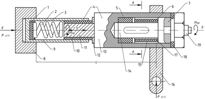
Fig. 2 shows the frictional and hydraulic parts of the damper. The reported 5.2 kN is an internal friction-pair force, not an external transverse track load. External excitation enters the shaft model through the loading terms and attachment motion.
Fig. 1Kinematic scheme of the patented torsion damper: 4 – torsion shaft; 8 – bogie frame; 16 – lever; 20, 26, 29 – guides; 21 – cam; 22 – car body; 23 – spherical head; 27 – splines; 28 – movable support; 30 – inclined groove
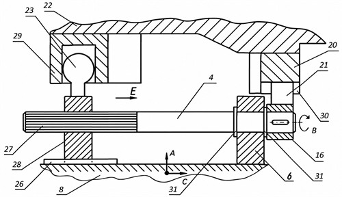
Fig. 2Longitudinal section of the hydro-friction torsion damper according to Patent IAP 07118 [8]
3. Mathematical model
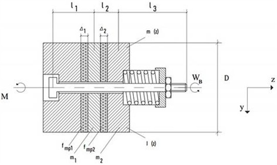
The shaft dynamics are modelled as coupled bending vibrations in two mutually perpendicular planes. Let denote the transverse displacement in plane , the line mass (kg/m), the flexural rigidity (N·m2), the external load per unit length (N/m), the dissipative reaction (N/m), and the distributed linear restoring coefficient (N/m2). Small-deflection Euler-Bernoulli bending is assumed on each smooth segment. The calculation scheme and characteristic axial regions used in the shaft model are shown in Fig. 3. Before introducing coefficient notation, the fixed-frame balance is:
The variable-rigidity elastic operator must be expanded before division by :
Hence the elastic coefficients in the two displacement planes are:
Fig. 3Calculation scheme of the variable-section shaft; l1-l3 are characteristic regions and Δ1, Δ2 are friction-disc thicknesses
For constant , and . Thus A1 and B1 have units of m2/s2, A2 and B2 have units of m3/s2, and A3 and B3 have units of m4/s2. The factor 2 in A2 and B2 follows directly from the product rule. Derivatives of do not enter these elastic coefficients because the elastic operator is expanded before mass normalization.
The displacement coefficients A4 and B4 have a different physical origin and cannot be obtained from , and alone. If the coordinate basis rotates at a prescribed constant angular speed and the restoring directions are aligned with that basis, then:
The corresponding Coriolis terms have opposite signs: in the y-equation and –2 in the -equation. The excitation angular frequency is a separate quantity and is not identified with . For a non-rotating verification frame with no distributed restoring stiffness, 0 and therefore 0. No unmeasured rotation rate or restoring stiffness is assigned to the device.
The source model represents the variable shaft properties by sinusoidal effective-property functions before their piecewise-linear numerical approximation:
These functions are retained as the source effective-property law; assigning the same multiplier to and should not be interpreted as diameter variation alone. The source symbols and are retained only as reported effective-property functions; they are not identified with the restoring coefficient without a separately defined force law and compatible units. The external dynamic excitation is represented in the source model by the harmonic-impulse form:
where denotes the excitation angular frequency, and and are the load amplitudes. Their calibrated physical values are not available in the source material.
4. Boundary conditions and numerical procedure
The shaft interval is divided in the source calculation into 100 sections. Two ideal hinged supports are used at 0 and ; transverse deflection and bending moment are zero at both ends:
The original procedure uses Fourier separation, a one-sided Laplace transform, piecewise-linear spatial coefficients, iterative eigenfrequencies, and Gaussian elimination or Cramer’s rule in Mathcad 15.
For mesh convergence, a separate spatial benchmark avoids unavailable device loads. With and , , simply supported ends and exact displacement . The manufactured verification load is obtained by substitution and is not measured track excitation. Cubic Hermite meshes 50, 100, 200 and 400 are compared by relative curvature-energy error eE and maximum normalized bending-moment error ; the latter uses the exact maximum dimensionless moment .
Table 1Mesh-convergence verification for the normalized variable-rigidity benchmark
No | , % analytical rigidity | , % analytical rigidity | , % linear interpolation | , % linear interpolation |
50 | 0,01471 | 0,03288 | 0,02116 | 0,04932 |
100 | 0,00368 | 0,00822 | 0,00529 | 0,01234 |
200 | 0,00092 | 0,00206 | 0,00132 | 0,00308 |
400 | 0,00023 | 0,00051 | 0,00033 | 0,00077 |
Mesh doubling reduces both errors by approximately four, indicating second-order convergence. At 100, analytical-property errors are 0.00368 % and 0.00822 %; linear interpolation gives 0.00529 % and 0.01234 %. An independent 80-term Rayleigh-Ritz calculation gives dimensionless frequencies 9.8287247, 39.2944906 and 88.7992304 versus 9.828725, 39.29449 and 88.79924 for 100 Hermite elements; the maximum difference is approximately 1.1×10⁻⁵ %. Thus 100 is sufficient for this benchmark, but this does not establish mesh independence of the complete damper model.
Field observations give dominant horizontal/vertical frequencies of 3-5/7-12 Hz and piston velocities up to 520/580 mm/s in compression/rebound. They describe operating conditions but do not identify shaft load. Because synchronized transmitted-force, attachment-displacement or shaft-strain records are unavailable, the data are not used to calibrate , or validate stresses; no quantitative attenuation, stress-reduction or fatigue-life claims are made.
The source reports heat-treated 20KhN3A limits of 430-650 MPa (normal endurance), 240-310 MPa (shear endurance), 850-1110 MPa (yield) and 950-1450 MPa (ultimate), and applies a Goodman-type assessment [14]. The required fatigue safety factor 2 is a design requirement, not a result of this article:
The source reports a mean stiffness of 425 kN/m. Because this quantity has the units of translational stiffness, it is retained only as an equivalent assembly parameter and is not substituted for the shaft flexural rigidity EI, whose units are N·m2.
5. Numerical parameters and results
The parameters directly reported in the source numerical model are summarized in Table 2.
Table 2Parameters used in the source numerical model
Parameter | Value | Source interpretation |
Shaft regions | 7 | Variable mass and bending rigidity |
Spatial subdivision | 100 sections | Source Mathcad 15 calculation |
Diameter states | 25 / 24 / 23 mm | Manufactured / overhaul / TR-3 |
Compressed calculation length | 146.2 mm | Source geometry |
Maximum length | 187.5 mm | Maximum extended state |
Movable-disc distance | 67 mm; 62 mm in working condition | Source geometry |
Total damper mass | 15 kg | Source parameter |
Internal friction force | 5.2 kN | Friction-pair force; not an external load |
Reported mean assembly stiffness | 425 kN/m | Equivalent assembly parameter; not EI |
Measured piston velocity | 520 / 580 mm/s | Compression / rebound |
Dominant measured frequencies | 3-5 / 7-12 Hz | Horizontal / vertical |
Material | 20KhN3A, heat-treated | Strength limits used in fatigue assessment |
Required fatigue safety factor | 2 | Design requirement |
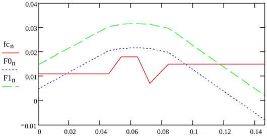
Fig. 4 compares the piecewise representation of the variable shaft-property functions from the source calculation with their spline approximation. The curves reproduce the principal spatial changes while removing discontinuities in the numerical representation. The source plot is retained only to illustrate the approximation of these functions and should not be interpreted as a stress-distribution diagram.
The former response plot is omitted because its ordinate cannot be traced to calibrated force, displacement or stress; it therefore cannot be relabelled in MPa or used to derive stress-reduction percentages.
6. Conclusions
1) The coupled two-plane shaft model is formulated with an explicitly expanded variable-rigidity operator. The elastic coefficients - and - follow directly from and ; and require separately defined rotational and restoring inputs and cannot be inferred from , and alone.
Fig. 4Piecewise and spline representations of the normalized variable shaft-property functions from the source calculation
2) A mesh-refinement verification of the stated variable-coefficient benchmark gives approximately second-order convergence from 50 to 400 elements. At 100 elements, the errors for analytical properties are 0.00368 % in curvature energy and 0.00822 % in sampled bending moment; with linear property interpolation, they are 0.00529 % and 0.01234 %. These values support the use of 100 subdivisions for the stated benchmark but do not establish mesh independence of the complete uncalibrated device model.
3) The source design data retained in the model include seven shaft regions, diameters of 25, 24 and 23 mm, a compressed length of 146.2 mm, a maximum length of 187.5 mm, a total damper mass of 15 kg, and an internal friction force of 5.2 kN.
4) The available frequency ranges of 3-5 Hz and 7-12 Hz and piston velocities of 520 mm/s in compression and 580 mm/s in rebound characterize operating conditions only. In the absence of calibrated transmitted loads and synchronized strain measurements, quantitative claims of stress reduction, vibration attenuation, or fatigue-life improvement are not made.
References
-
S. Iwnicki, M. Spiryagin, C. Cole, and T. Mcsweeney, Handbook of Railway Vehicle Dynamics. Boca Raton, FL, USA: CRC Press, 2019, https://doi.org/10.1201/9780429469398
-
M. Spiryagin, C. Cole, Y. Q. Sun, M. Mcclanachan, V. Spiryagin, and T. Mcsweeney, Design and Simulation of Rail Vehicles. Boca Raton, FL, USA: CRC Press, 2014, https://doi.org/10.1201/b17029
-
W. L. Wang, Z. R. Zhou, D. S. Yu, Q. H. Qin, and S. Iwnicki, “Rail vehicle dynamic response to a nonlinear physical ‘in-service’ model of its secondary suspension hydraulic dampers,” Mechanical Systems and Signal Processing, Vol. 95, pp. 138–157, Apr. 2017, https://doi.org/10.1016/j.ymssp.2017.03.031
-
B. Titurus, J. Du Bois, N. Lieven, and R. Hansford, “A method for the identification of hydraulic damper characteristics from steady velocity inputs,” Mechanical Systems and Signal Processing, Vol. 24, No. 8, pp. 2868–2887, Jun. 2010, https://doi.org/10.1016/j.ymssp.2010.05.021
-
G. Jehle and A. Fidlin, “Hydrodynamic optimized vibration damper,” Journal of Sound and Vibration, Vol. 440, pp. 100–112, Feb. 2019, https://doi.org/10.1016/j.jsv.2018.10.008
-
T. Deng, L. Zhao, and F. Jin, “Flexural wave rainbow trapping effect in the periodic non-uniform Euler–Bernoulli beams and its application in energy harvesting,” Mechanics of Materials, Vol. 190, p. 104892, Mar. 2024, https://doi.org/10.1016/j.mechmat.2023.104892
-
L. Schickhofer and J. Wimmer, “Fluid-structure interaction and dynamic stability of shock absorber check valves,” Journal of Fluids and Structures, Vol. 110, p. 103536, Mar. 2022, https://doi.org/10.1016/j.jfluidstructs.2022.103536
-
G. A. Khromova, S. A. Khromov, D. O. Radjibaev, M. S. Valiev, I. S. Kamalov, and M. A. Makhamadalieva, “Hydraulic vibration damper of torsion type,” Patent of the Republic of Uzbekistan No. IAP 07118, 2022.
-
G. A. Khromova and M. A. Makhamadalieva, “Calculation diagram of the hydrodynamic friction support of the flexible shaft of the hydro-friction vibration damper used in railway transport,” Universum: Engineering Sciences, No. 7-1 (76), pp. 77–80, 2020.
-
G. A. Khromova, I. S. Kamalov, and M. A. Makhamadalieva, “Development of a methodology for solving the equations of bending vibrations of the hydro friction damper of the electric train of disk type,” in AIP Conference Proceedings, Vol. 2656, p. 020014, 2022, https://doi.org/10.1063/5.0108814
-
G. Khromova, M. Makhamadalieva, and S. Khromov, “Development of a dynamic model for calculating the strength of a hydraulic oscillation damper for high-speed electric train Afrosiab,” AIP Conference Proceedings, Vol. 2476, No. 1, 020034, 2023, https://doi.org/10.1063/5.0104687.
-
G. Khromova, M. Makhamadalieva, and S. Khromov, “Development of a dynamic model for calculating the strength of a hydraulic oscillation damper for high-speed electric train Afrosiab,” in AIP Conference Proceedings, Vol. 2683, p. 020034, May 2023, https://doi.org/10.1063/5.0104687
-
G. A. Khromova, M. A. Makhamadalieva, and I. S. Kamalov, “Generalized dynamic model for the calculation of torsion type hydraulic vibration damper for electric rolling stock,” in AIP Conference Proceedings, Vol. 2948, p. 020017, Nov. 2023, https://doi.org/10.1063/5.0165594.
-
V. P. Kogaev, Strength Calculations under Time-Varying Stresses. Moscow, USSR: Mashinostroenie, 1977.
About this article

The authors have not disclosed any funding.
The datasets generated during and/or analyzed during the current study are available from the corresponding author on reasonable request.
The authors declare that they have no conflict of interest.

