Abstract
This study presents a novel tensegrity-based vibratory conveying platform capable of transporting parts in specified directions. The proposed platform integrates a tensegrity structure with three cam-driven excitation mechanisms to generate controlled vibratory motions for directional part conveyance. First, the structural configuration and operating principle of the platform are described in detail. Subsequently, kinematic simulations are conducted to investigate the motion characteristics and verify the feasibility of the proposed design. To validate the simulation results, an experimental prototype is developed and tested under various directional conveying. Both simulation and experimental results demonstrate that the proposed platform can accurately convey parts along designated directions with satisfactory repeatability and accuracy.
Highlights
- Novel Tensegrity-Based Platform: A novel vibratory conveying platform integrating a compliant tensegrity structure with three independent cam-driven actuators is proposed.
- Multi-Directional Motion Control: Multi-directional part conveying in the horizontal plane is achieved by independently adjusting the rotational speed ratios of the three cam mechanisms.
- High Directional Conveying Accuracy: Kinematic ADAMS simulations and experimental prototype testing confirm high directional accuracy, with a maximum experimental deviation of only 1.62°.
1. Introduction
Vibratory conveyors play a crucial role in a wide range of industrial material-handling applications. A conveyor is a machine that uses an oscillating device to advance one or several objects [1]. It can be classified as a single or multi-drive trough based on the mounting/drive arrangements [2]. Alternatively, it can be categorized as a vibratory bowl conveyor or a linear bowl conveyor based on the route of part advancement [3]. Despite their widespread use, conventional vibratory conveyors generally provide only single-degree-of-freedom (DoF) motion and often rely on bulky and mechanically complex structures that result in relatively high energy consumption. In this study, a vibratory conveying platform refers to a vibratory conveyor that can advance parts with the motion of two or more DoFs. Compared with other part-handling devices, vibratory conveyors offer several advantages, including high productivity, operational flexibility, and reliability. Historically, cam-driven mechanisms have been utilized as vibration exciters due to their ability to provide precise amplitude control and high force transmission efficiency, which are often superior to the limitations of piezoelectric or electromagnetic exciters in high-load or long-stroke applications. While piezoelectric exciters offer high-frequency response, they often lack the stroke depth required for certain conveying tasks. Cam mechanisms, by contrast, allow for tailored motion profiles that can specifically exploit the non-linear dynamics of tensegrity structures. Consequently, increasing research attention has been directed toward the development of long-stroke, high-load, and highly controllable conveying systems.
Tensegrity structures consist of self-equilibrated, prestressed compression and tension members, commonly referred to as struts and cables, respectively [4]. Owing to their lightweight characteristics, geometric efficiency, controllability, and deployability, tensegrity structures have attracted considerable research interest over the past several decades. As a result, they have been applied in numerous fields, including civil engineering [5], aerospace engineering [6], biology [7], and robotic systems and control [8-9]. Furthermore, tensegrity structures exhibit significant potential as controllable and adaptive engineering systems [10].
Numerous studies have been devoted to the improvement of vibratory conveying technologies. In 1996, Sloot et al. [11] investigated the conveying speed of granular materials using vibratory conveyors. Hu et al. [12] developed a single-axis vibratory feeder in 2005 by decoupling the motion of a conventional vibratory feeder. Grevenstette et al. [13], in 2009, modeled pattern formation of granular matter on vibratory conveyors. In 2012 and 2013, Hsieh and Tsai [14, 15] proposed a novel vibratory bowl feeder and conducted its design and analysis. In 2013, Rade et al. [16] experimentally investigated a vibratory conveying system driven by piezoelectric actuators. Subsequently, Hsieh and Shih [17] proposed a resonantly driven inline conveyor actuated by a piezoelectric actuator in 2014. Sturm and Pesik [18] examined the dynamic characteristics and operating parameters of vibratory bowl conveyors through numerical simulations and experimental studies. In 2016, Czubak [19] developed a bidirectional vibratory conveyor capable of transporting parts in both forward and backward directions. More recently, Hsieh and Adhitya [20] investigated a novel three-DoF vibratory conveying platform in 2022. In 2024, Hsieh et al. [21] conducted a finite element analysis of a tensegrity-based vibratory conveying platform. Subsequently, Hsieh et al. [22] performed a simulation study of a piezoelectrically actuated tensegrity-based vibratory conveying platform in 2026.
Based on the existing literature, only two studies [21,22] have focused on tensegrity-based vibratory conveying platforms, both of which remain limited to simulation investigations. Among them, one study [22] employed piezoelectric actuators as the driving source, whereas the actuation method used in the other study [21] was not explicitly specified. Therefore, this study proposes a new cam-driven actuation approach for a tensegrity-based vibratory conveying platform. The feasibility and effectiveness of the proposed system are evaluated through both kinematic simulations and experimental prototype validation.
2. The proposed vibratory conveying platform
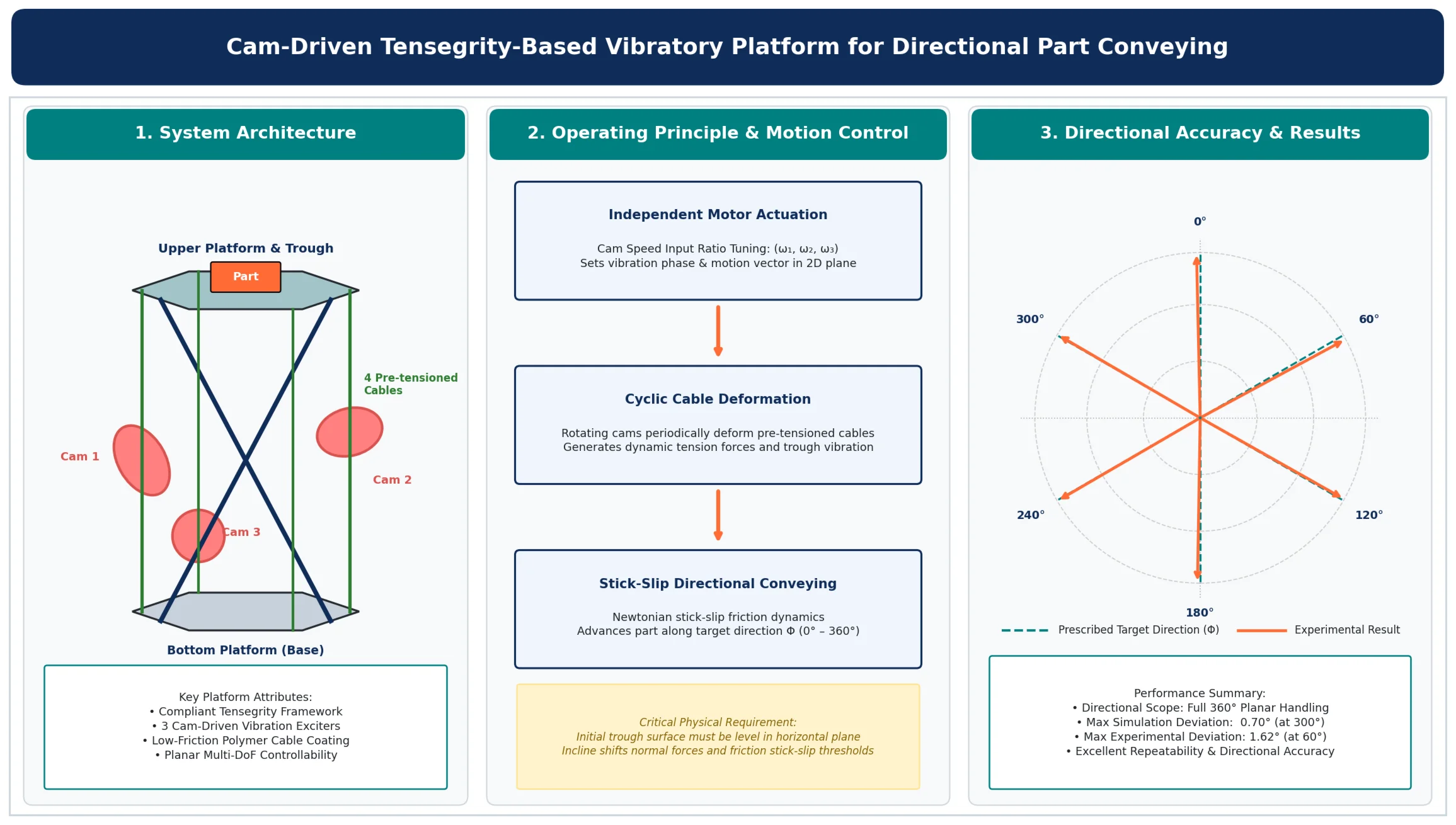
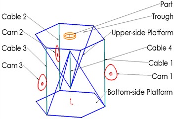
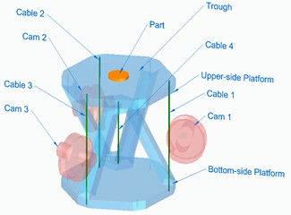
A vibratory conveyor generally consists of three primary components: an actuator that generates vibratory excitation, a conveying trough for material transportation, and flexible elements that transmit the generated vibrations from the actuator to the trough [20]. The proposed tensegrity-based vibratory conveying platform is shown in Fig. 1. The platform consists of two rigid platforms, four pre-tensioned cables, and three cam-driven actuators. To ensure structural reliability and mitigate wear during the sliding contact between the rigid cams and flexible cables, a specialized low-friction polymer coating is recommended to be applied to the cables. This interface minimizes the risk of non-linear tension spikes and protects the cables from accelerated wear over sustained cyclic loading, leveraging the inherent damping and flexibility of the tensegrity members to distribute impact forces. During operation, the rotating cams periodically interact with the cables, causing cyclic deformation and subsequent restoration. These cable deformations induce vibrations of the upper platform and conveying trough primarily within the horizontal plane. As a result, the generated vibratory motion enables the transportation of a part placed on the trough surface. By independently controlling the rotational speeds of the three cams, the vibration characteristics of the platform can be adjusted, thereby allowing the part to be conveyed in a desired direction.
The proposed tensegrity-based vibratory conveying platform integrates the unique characteristics of tensegrity structures with the advantages of vibratory conveying technology. Tensegrity systems possess several desirable attributes, including high controllability [23], lightweight construction [24], and excellent deployability [25]. Owing to their efficient integration of structural functionality and motion control, tensegrity structures provide a promising foundation for the development of multidirectional conveying systems. By exploiting the inherent flexibility, adaptability, and reconfigurability of tensegrity principles, the proposed platform offers a novel and effective approach for advanced vibratory conveying and material-handling applications.
Fig. 1Tensegrity-Based vibratory conveying platform
a) Schematic
b) Solid model
3. Kinematic simulation
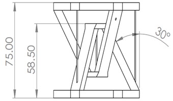
Kinematic simulations are conducted using ADAMS software. The geometric dimensions of the proposed platform are illustrated in Fig. 2, where all dimensions are given in millimeters (mm). The coordinate system of the moving platform is shown in Fig. 3. For a specified advancing direction, denoted by , the corresponding - and -components of the unit displacement vector are determined by and , respectively. The gravitational direction and contact parameters used in the simulation are presented in Fig. 4.
The simulation results for part advancement in the specified directions are summarized in Table 1. It can be observed that the simulated advancing directions are in close agreement with the prescribed directions, demonstrating the feasibility of the proposed conveying platform. The small discrepancies between the specified and simulated directions may be attributed to numerical approximation errors and uncertainties associated with the contact parameter settings. However, these deviations are negligible and therefore do not significantly affect the validity of the simulation results.
Fig. 2Dimensions
a) Front view
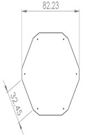
b) Top view
Fig. 3Specified advancing direction
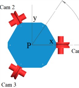
Fig. 4Contact parameters
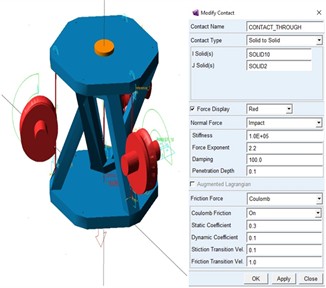
Table 1Simulation results
Cam input ratio (cam 1, cam 2, cam 3) | displacement (mm) | displacement (mm) | Simulation (°) | Ideal (°) | Deviation (°) |
1, 0, 0 | 9.694656 | 0.000571 | 0.003346 | 0 | 0.00093 |
1, 1, 0 | –6.999729 | 4.049684 | 59.948549 | 60 | 0.01429 |
0, 1, 0 | –8.631813 | –4.978001 | 119.972197 | 120 | 0.00772 |
0, 1, 1 | –13.838383 | 0.010252 | 180.042416 | 180 | 0.01178 |
0, 0, 1 | 8.000059 | –4.520050 | 240.533484 | 240 | 0.14819 |
1, 0, 1 | 3.203370 | 1.797752 | 299.301406 | 300 | 0.19405 |
4. Experiment
To validate the effectiveness of the proposed design, a prototype of the tensegrity-based vibratory conveying platform is constructed, as shown in Fig. 5. The experimental workflow of the test setup is illustrated in Fig. 6. The input signals required for the three actuators are generated in MATLAB Simulink and transmitted through a Sensoray-626 data acquisition (DAQ) card. These signals were subsequently amplified using an L298N motor driver to provide the required voltage levels for driving the RS-555 DC motors. During operation, the rotating cams periodically interact with the cables, causing cyclic cable deformation and restoration. This interaction generates dynamic tension forces that excite the trough and produce vibratory motion. Consequently, the platform is capable of conveying a part in a prescribed direction through controlled vibration.
Fig. 5Prototype
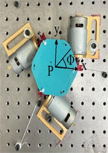
Fig. 6Control flowchart
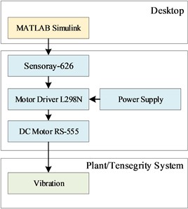
Table 2Experimental data
Cam input ratio (cam 1, cam 2, cam 3) | displacement (mm) | displacement (mm) | ||||||
Experiment 1 | Experiment 2 | Experiment 3 | Average | Experiment 1 | Experiment 2 | Experiment 3 | Average | |
1, 0, 0 | 13.29621 | 14.76982 | 16.31453 | 14.79352 | 0.83384 | 0.08638 | 0.06332 | 0.32785 |
0, 1, 1 | 8.58166 | 5.48463 | 10.16591 | 8.07740 | 4.98375 | 3.05375 | 5.051821 | 4.36311 |
0, 1, 0 | 12.54333 | 15.22325 | 11.00339 | 12.92333 | –7.10093 | –8.64530 | –6.15032 | –7.29885 |
0, 1, 1 | –18.24836 | –14.83453 | –17.40334 | –16.82876 | 0.32450 | 0.09556 | –1.25001 | –0.27664 |
0, 0, 1 | –18.88243 | –18.37531 | –5.58121 | –14.27965 | –11.26383 | –10.35602 | –3.31632 | –8.31206 |
1, 0, 1 | –10.08202 | –10.14042 | –10.42848 | –10.21697 | 5.91195 | 5.78668 | 6.17661 | 5.95842 |
Each experiment is repeated three times, and the averaged results are summarized in Table 2. The experimental results are further presented in Table 3. Based on the collected data, the vibratory motion characteristics, conveying performance, and directional controllability of the proposed platform are evaluated. The maximum directional deviation between the prescribed and measured advancing directions was 1.62° at a target direction of 60°. Considering the inherently stochastic nature of vibratory conveying, this deviation is relatively small and demonstrates the satisfactory directional accuracy of the proposed system.
Table 3Experiment results
Cam input ratio (Cam 1, cam 2, cam 3) | Experiment (◦) | Ideal (◦) | Deviation (◦) |
1, 0, 0 | –1.27 | 0 | –1.27 |
0, 1, 1 | 61.62 | 60 | 1.62 |
0, 1, 0 | 119.46 | 120 | –0.54 |
0, 1, 1 | 180.94 | 180 | 0.94 |
0, 0, 1 | 239.80 | 240 | -0.2 |
1, 0, 1 | 300.25 | 300 | 0.25 |
These experimental results show that the tensegrity structure offers several advantages for vibration generation and material conveying applications. These characteristics simplify the process of vibration generation as they do not require large amounts of energy and complex mechanisms. This is due to the relatively lower stiffness of tensegrity structures compared to bulk structures. However, it should be acknowledged that the appropriate boundary conditions for advancing parts will highly affect the specific direction precisions. A phenomenon was observed that the movement of parts on the vibration platform is affected by the initial angle of the trough's surface, in accordance with the laws of classical Newtonian mechanics. It was found that an initial horizontal trough surface is required for the experiment to work accurately. The self-stress is necessary for stabilizing the structure by activating the geometrical stiffness of the tensegrity members [26]. The limitation can be solved through configuration adjustments and cable tension tuning, leveraging the inherent flexibility and tunability of tensegrity structures.
The experimental results indicate that the tensegrity structure provides several advantages for vibration generation and material-conveying applications. In particular, the lightweight and compliant nature of tensegrity systems enables efficient vibration generation without the need for complex transmission mechanisms or high energy consumption. This characteristic is primarily attributed to the relatively low structural stiffness of tensegrity systems compared with conventional rigid-body structures. Experimental observations reveal that the motion of the conveyed part is sensitive to the initial inclination of the trough surface, consistent with the principles of classical Newtonian mechanics. More specifically, accurate directional conveying requires the trough surface to be initially leveled in the horizontal plane. This requirement is rooted in classical Newtonian mechanics; an initial incline introduces a gravitational force component parallel to the trough, which alters the net normal force between the part and the surface. Consequently, this shift modifies the stick-slip friction thresholds – the point at which the part transitions from sticking to the vibrating trough to sliding across it. Even a minor deviation from the horizontal plane can cause the part to drift preferentially toward the incline, overriding the intended directional vibrations generated by the cam-driven system. Furthermore, self-stress plays a critical role in stabilizing the tensegrity structure by activating the geometric stiffness of its members.
5. Conclusions
This study proposed a novel cam-driven tensegrity-based vibratory conveying platform for directional part transportation. The feasibility and effectiveness of the proposed platform were validated through both kinematic simulations and experimental prototype testing. The results demonstrated that the platform is capable of conveying parts accurately in prescribed directions. The maximum directional deviation observed in the experiments is 1.62375° at a target direction of 60°, whereas the maximum deviation obtained from the simulations is 0.69859° at a target direction of 300°. These results confirm the capability of the proposed platform to achieve precise directional conveying with satisfactory accuracy. Future work will focus on the development of closed-loop control strategies to further improve directional accuracy and further optimization of the cam-cable interface to enhance long-term durability.
References
-
F. Kipriyanov and P. Savinykh, “The results of the study of the vibratory conveying machine operating modes,” Transportation Research Procedia, Vol. 63, pp. 721–729, Jun. 2022, https://doi.org/10.1016/j.trpro.2022.06.067
-
C. R. Woodcock and J. S. Mason, Bulk Solids Handling: An Introduction to the Practice and Technology. Dordrecht, The Netherlands: Springer, 1988.
-
P. U. Frei, “Theory, design and implementation of a novel vibratory conveyor,” Swiss Federal Institute of Technology, ETH Zurich, Zurich, Switzerland, 2002, https://doi.org/10.3929/ethz-a-004304818
-
R. B. Fuller, “Tensile-integrity structures,” U.S. Patent 3 063 521, 1962.
-
Y. Feng, X. Yuan, and A. Samy, “Analysis of new wave-curved tensegrity dome,” Engineering Structures, Vol. 250, p. 113408, Nov. 2021, https://doi.org/10.1016/j.engstruct.2021.113408
-
M. Chen, R. Goyal, M. Majji, and R. E. Skelton, “Design and analysis of a growable artificial gravity space habitat,” Aerospace Science and Technology, Vol. 106, p. 106147, Aug. 2020, https://doi.org/10.1016/j.ast.2020.106147
-
S. Graham, Biotensegrity: The Structural Basis of Life. East Sussex, U.K.: Handspring Publishing, 2014.
-
S. Liu, Q. Li, P. Wang, and F. Guo, “Kinematic and static analysis of a novel tensegrity robot,” Mechanism and Machine Theory, Vol. 149, p. 103788, Feb. 2020, https://doi.org/10.1016/j.mechmachtheory.2020.103788
-
Z. Wang, K. Li, Q. He, and S. Cai, “A Light-Powered Ultralight Tensegrity Robot with High Deformability and Load Capacity,” Advanced Materials, Vol. 31, No. 7, p. 1806849, 2018, https://doi.org/10.1002/adma.201806849
-
Y. Ma et al., “Meta-tensegrity: Design of a tensegrity prism with metal rubber,” Composite Structures, Vol. 206, pp. 644–657, Aug. 2018, https://doi.org/10.1016/j.compstruct.2018.08.067
-
E. M. Sloot and N. P. Kruyt, “Theoretical and experimental study of the transport of granular materials by inclined vibratory conveyors,” Powder Technology, Vol. 87, No. 3, pp. 203–210, Jul. 2002, https://doi.org/10.1016/0032-5910(96)03091-4
-
Z. Hu, G. P. Maul, and D. Farson, “Piezo actuated vibratory feeding with vibration control,” International Journal of Production Research, Vol. 45, No. 5, pp. 1089–1100, Jul. 2006, https://doi.org/10.1080/00207540500515156
-
M. Grevenstette and S. J. Linz, “Model for pattern formation of granular matter on vibratory conveyors,” Chaos, Solitons and Fractals, Vol. 39, No. 4, pp. 1896–1902, 2007, https://doi.org/10.1016/j.chaos.2007.06.101
-
W.-H. Hsieh and C.-H. Tsai, “Design and analysis of a novel vibrating conveyor,” Advanced Science Letters, Vol. 9, No. 1, pp. 62–67, Apr. 2012, https://doi.org/10.1166/asl.2012.2570
-
W. H. Hsieh and C. H. Tsai, “Kinematic analysis of a novel vibratory bowl feeder,” Vibroengineering Procedia, Vol. 2, pp. 92–97, 2013.
-
D. Rade, E. Albuquerque, L. Figueira, and J. Carvalho, “Piezoelectric driving of vibration conveyors: an experimental assessment,” Sensors, Vol. 13, No. 7, pp. 9174–9182, 2013, https://doi.org/10.3390/s130709174
-
W.-H. Hsieh and N.-N. Shih, “On an inline conveyor resonantly driven by piezoelectric actuators,” Journal of Vibroengineering, Vol. 16, No. 5, pp. 2164–2170, 2014, https://doi.org/10.21595/jve.2014.15294
-
M. Sturm and L. Pesik, “Determination of a vibrating bowl feeder dynamic model and mechanical parameters,” Acta Mechanica Et Automatica, Vol. 11, No. 3, pp. 243–246, Sep. 2017, https://doi.org/10.1515/ama-2017-0038
-
P. Czubak, “Vibratory conveyor of the controlled transport velocity with the possibility of the reversal operations,” Journal of Vibroengineering, Vol. 18, No. 6, pp. 3539–3547, Sep. 2016, https://doi.org/10.21595/jve.2016.17257
-
W.-H. Hsieh and Adhitya, “On a novel micro vibratory platform with 3 DoFs,” Microsystem Technologies, Vol. 28, No. 1, pp. 383–394, May 2020, https://doi.org/10.1007/s00542-020-04860-3
-
Wen-Hsiang Hsieh, Chen-Ji Pan, and Yen-Chun Hsieh, “Finite Element Analysis of a Novel Tensegrity-Based Vibratory Platform,” International Journal of Engineering and Technology Innovation, Vol. 14, No. 1, pp. 58–66, Dec. 2023, https://doi.org/10.46604/ijeti.2023.13230
-
Wen-Hsiang Hsieh, Samudra Prasetyo, and Chen-Ji Pan, “Modeling and analysis of a tensegrity-based vibratory platform driven by piezoelectric actuators using IronCAD,” Proceedings of Engineering and Technology Innovation, Vol. 32, pp. 43–55, Jan. 2026, https://doi.org/10.46604/peti.2025.15076
-
R. Goyal, M. Majji, and R. E. Skelton, “Integrating structure, information architecture and control design: Application to tensegrity systems,” Mechanical Systems and Signal Processing, Vol. 161, p. 107913, May 2021, https://doi.org/10.1016/j.ymssp.2021.107913
-
Y. Wang, X. Xu, and Y. Luo, “Minimal mass design of active tensegrity structures,” Engineering Structures, Vol. 234, p. 111965, Feb. 2021, https://doi.org/10.1016/j.engstruct.2021.111965
-
J. M. Mirats Tur, S. Hernandez Juan, and A. G. Rovira, “Dynamic equations of motion for a 3-bar tensegrity based mobile robot,” in 2007 IEEE Conference on Emerging Technologies and Factory Automation (EFTA 2007), pp. 1334–1339, 2008, https://doi.org/10.1109/efta.2007.4416935
About this article

The support of the National Science and Technology Council, Republic of China (Taiwan), under Grants NSTC 113-2221-E-150-022 is gratefully acknowledged.
The datasets generated during and/or analyzed during the current study are available from the corresponding author on reasonable request.
The authors declare that they have no conflict of interest.

