Abstract
The paper focuses on the design peculiarities and kinematic analysis of a novel shaking conveyor equipped with three interconnected transporting and screening trays. The goal is to develop a comprehensive mathematical model to describe the system’s motion and analyze the interplay between the trays, providing a basis for improved design and optimization. The scientific novelty lies in the detailed kinematic study of this specific multi-tray configuration, particularly the interaction of the dual beam systems actuating the intermediate tray, leading to complex coupled motion profiles. The practical value of the research is substantial for designing and optimizing such multi-functional vibratory equipment, as the kinematic data (displacements, velocities, accelerations) provide critical insights into material-tray interaction, aiding in predicting and enhancing material processing efficiency, estimating inertial loads for robust structural design, and informing vibration isolation strategies. The methods employed include the development of a kinematic diagram and corresponding motion equations for the multi-loop linkage mechanism, followed by numerical modeling of the system’s motion using Wolfram Mathematica software. The main results characterize the complex motion profiles for a steady-state operational frequency of 10 Hz, revealing distinct amplitudes and near-linear inclined trajectories for key hinges representing each tray. Notably, the upper tray exhibited the most significant displacements and accelerations, with horizontal accelerations reaching approximately 3 g and vertical accelerations around 1.3 g, indicating a motion profile conducive to effective material lifting, “throwing”, and bed stratification. Scopes of further research include a complete dynamic analysis incorporating mass properties and driving forces, experimental validation of the models, optimization of geometric and operational parameters, integration with Discrete Element Method (DEM) simulations for detailed material flow analysis, and investigations into wear, fatigue life, and advanced control strategies.
Highlights
- A three-tray shaking conveyor is introduced, in which paired beam systems couple tray motions, enabling simultaneous transport and staged screening.
- A complete kinematic model of the multi-loop linkage is developed; hinge displacements, velocities, and accelerations are computed and validated via numerical runs at 10 Hz.
- Hinge trajectories are shown to be nearly linear and ≈25° inclined, with in-phase x–y oscillations; motion amplitudes are observed to increase from the lower to the upper tray.
- Strong excitations on the upper tray are quantified - ~3g horizontal and ~1.3g vertical - by which particle lifting, throwing, and bed stratification are promoted, enhancing screening efficiency.
- Design guidance is provided for inertial loads, structural sizing, and isolation; future work is outlined on full dynamics, experiments, geometry tuning, and DEM-coupled flow analysis.
1. Introduction
Shaking conveyors are integral components in a multitude of industrial processes, facilitating the transport, separation, and classification of bulk materials and individual parts. Their operational principle relies on controlled vibrations to induce material movement, offering advantages such as gentle handling, energy efficiency, and the ability to perform multiple functions simultaneously, like conveying and screening. The design and optimization of these machines necessitate a thorough understanding of their kinematic and dynamic characteristics to ensure efficient operation, minimize wear, and predict material behavior. This becomes particularly complex in systems employing multiple transporting and screening trays, where inter-tray dynamics and the combined effects of conveying and separation processes must be considered. The body of research on vibratory material transport and screening is extensive, with contributions covering fundamental principles, specific machine designs, and advanced modeling techniques. Early investigations into particle motion laid the groundwork for understanding material behavior on vibrating surfaces. For instance, Kilikevičius et al. [1] focused on the motion characteristics of parts on a platform subjected to planar oscillations, providing insights into basic transport phenomena. Complementing this, El Banna et al. [2] explored the transportation of objects on an inclined plane that oscillates in the longitudinal direction, specifically addressing the role of dynamic dry friction manipulations.
Advancements in screening technology have been significantly supported by detailed modeling and simulation. Guo et al. [3] utilized an integrated CFD-DEM-FEM approach to simulate the screening characterization of double-deck vibrating screens, particularly for slurry TBM tunneling applications. The dynamics of flip-flow vibrating screens, known for their efficiency with difficult materials, have been a particular focus. Lin et al. developed a rigid-flexible coupled dynamic model for these screens, importantly considering the effects of the processed materials themselves [4], and subsequently proposed a method for stabilizing the vibration amplitude of flip-flow screens through the use of piecewise linear springs [5]. The operational dynamics of various conveyor types and excitation systems have also been thoroughly examined. Żmuda and Czubak [6] analyzed the operation of a novel single-vibrator conveyor, particularly its performance on the falling slope of the second resonance. More complex systems, such as three-mass vibratory systems with twin crank-slider excitation mechanisms, were dynamically analyzed by Korendiy et al. [7]. The same research group also contributed to the modeling and experimental investigation of general vibratory conveyor operating conditions [8]. The control aspects of vibratory screening conveyors were addressed by Kachur et al. [9], who studied the dynamics of such systems when equipped with a controllable centrifugal exciter.
Resonance phenomena and system optimization are critical for efficient vibratory machine design. Despotović et al. [10] provided mathematical modeling, simulations, and experimental results for resonant linear vibratory conveyors that utilize electromagnetic excitation. The dynamics of resonance single-mass vibratory machines operating based on the Sommerfeld effect were detailed by Filimonikhin et al. [11]. Efforts to optimize the response of underactuated vibration generators were made by Belotti et al. [12], who explored dynamic structural modification and the shaping of excitation forces. Similarly, Bettega et al. [13] focused on integrated inverse dynamics and optimized mechanical design in underactuated linear vibratory feeders subjected to periodic excitation. The principles of vibration mechanics find applications beyond conveying and screening. For example, Korendiy et al. also investigated the dynamics of vibratory finishing machines used for single-sided lapping and polishing of flat surfaces [14], and studied the influence of the impact gap value on the average translational speed of wheeled vibration-driven robots [15]. These studies, while not directly on conveyors, contribute to the broader understanding of controlled vibratory motion. In terms of advanced mechanical structures, Tătaru et al. [16] presented work on the synthesis and functional optimization of a vibratory machine featuring a parallel mechanism structure.
Detailed analyses of vibratory feeders and conveyor mechanisms continue to refine design approaches. Buzzoni et al. [17] conducted a motion analysis of a linear vibratory feeder, combining dynamic modeling with experimental verification. Nguyen and Golikov [18] analyzed material particle motion and aimed to optimize the parameters of vibration for a two-mass GZS vibratory feeder. Algazy [19] focused on substantiating the dynamic parameters of shaking conveyor mechanisms, a foundational step for accurate modeling. Yeleukulov et al. [20] provided a mechanical analysis of vibratory conveyor mechanisms, while Zhauyt et al. [21] concentrated on determining the kinematic and dynamic characteristics of oscillating conveyor mechanisms. The underlying linkage systems are also crucial, with Umbetkulov et al. [22] performing a dynamic force analysis of a six-link planar mechanism, often a component in such vibratory machinery. Further exploring specific screen designs, Li et al. [23] investigated the dynamic and vibration behaviors of a flip-flow screen incorporating a crankshaft-link structure.
The nonlinear dynamics and specific excitation components are also key research areas. Alışverişçi investigated the nonlinear behavior of vibrational conveyors equipped with single-mass crank-and-rod exciters [24] and later extended this to the nonlinear analysis of such conveyors with non-ideal crank-and-rod exciters [25]. The design of excitation sources themselves has been advanced by Lanets et al. [26], who developed a controllable crank mechanism for exciting oscillations in vibratory equipment. More directly related to combined functionality, Korendiy et al. [27] performed a kinematic analysis of an oscillatory system designed for a shaking conveyor-separator. Building on this, Kachur and Korendiy [28] examined the dynamic behavior of a vibratory screening conveyor specifically equipped with a crank-type exciter.
While these studies offer valuable insights into various aspects of vibratory machinery, including particle motion, screen design, conveyor dynamics, excitation methods, and control, a comprehensive kinematic and dynamic analysis of shaking conveyors featuring multiple transporting and screening trays simultaneously, considering their coupled interactions and the combined effects of conveying and multi-stage screening, remains an area requiring further detailed investigation. This paper aims to address this gap by presenting a detailed kinematic analysis of a shaking conveyor system equipped with multiple transporting and screening trays. The study focuses on developing a comprehensive mathematical model to describe the system’s motion and analyze the interplay between the trays. The findings are intended to provide a basis for the improved design, control, and optimization of such multi-functional vibratory systems.
2. Research methodology
2.1. General design of the shaking conveyor
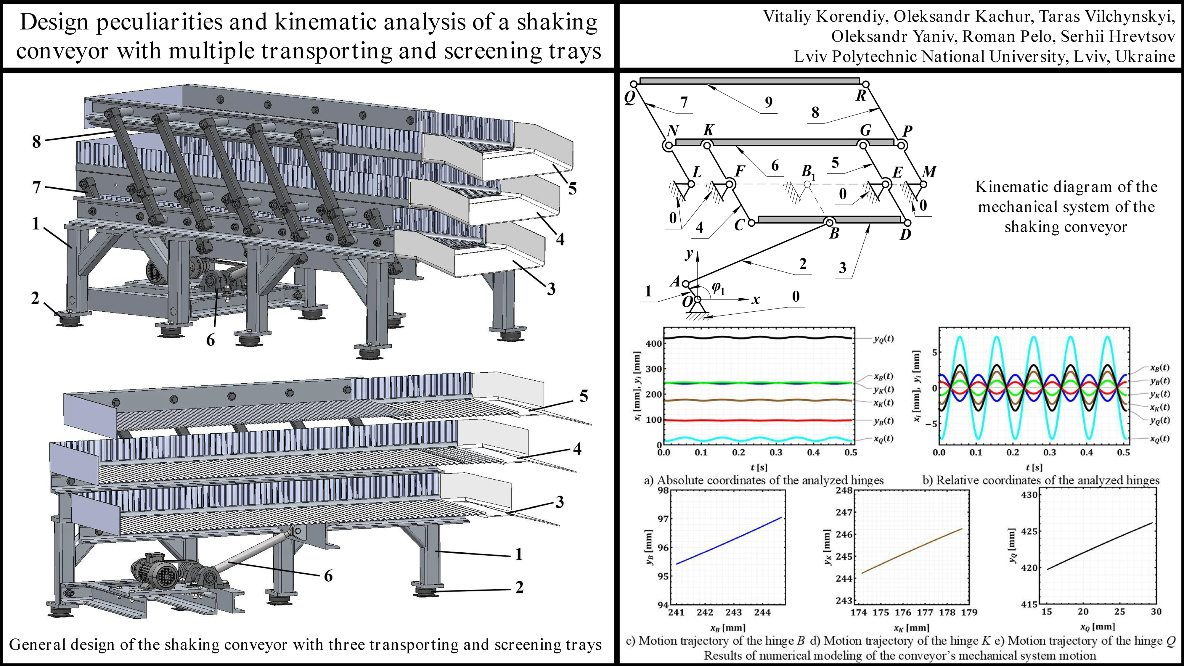
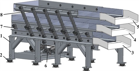
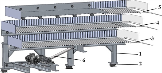
The shaking conveyor depicted in Fig. 1 is a multi-functional machine designed for both transporting and screening materials simultaneously across three distinct operational levels. Its design incorporates several key features that enable this complex operation.
The entire assembly is supported by a robust machine frame 1, which provides the structural integrity for all moving and stationary components. This frame is elevated from the ground and rests on vibration isolators 2. These isolators (elastomeric or spring-based) are crucial for minimizing the transmission of vibrations generated during operation to the supporting floor and surrounding environment, thus reducing noise and potential structural interference. The three trays – the lower conveying tray 3, the intermediate conveying and screening tray 4, and the upper conveying and screening tray 5 – are arranged vertically, one above the other. This tiered arrangement allows for the sequential processing of material.
The primary motion for the conveyor system is generated by a drive 6, equipped with an electric motor coupled with a belt transmission with a mechanical exciter (crank-type (eccentric-type) excitation mechanism). This drive unit is mounted on the lower part of the machine frame (or on a dedicated sub-frame). The drive generates reciprocating motion, which is then transmitted to the trays. The nature of this motion (amplitude, frequency, and direction) is critical to the conveying and screening efficiency.
System 7 of beams actuating lower and intermediate trays consists of several inclined connecting beams (rockers), which link the corresponding oscillating members 3 and 4 to the pushing rod of the drive mechanism 6. The geometry and linkage points of this system are designed to impart a specific type of motion to these two trays. It’s possible that this system creates a phase difference or a differential amplitude between the lower and intermediate trays to optimize material transfer and initial screening.
Similar to system 7, the second set 8 of inclined connecting beams (rockers) links the upper oscillating member (conveying and screening tray 5) to the intermediate tray 4. The interaction of these two beam systems (7 and 8) on the intermediate tray 4 is the major novelty of this design. The intermediate tray is actuated by both systems. This suggests a complex motion profile for the trays, designed to enhance both conveying and screening efficiency. The upper and intermediate trays move in a similar phase, while the lower tray moves in a counter-phase.
The lower tray 3 is primarily designed for transporting material. Its surface is clearly perforated and suitable for conveying all material that has passed through the upper screens. The intermediate tray 4 serves a dual purpose. It conveys material along its length while simultaneously screening it. The surface of this tray is clearly perforated with a hole-type screen mesh. This allows finer particles to fall through to the lower tray 3, while oversized particles continue to be transported along the intermediate tray 4. Similar to the intermediate tray, the upper tray 5 also performs both conveying and screening. It is also equipped with a perforated surface and rod-type screen mesh. Material is fed onto this tray first. Finer particles pass through its screen onto the intermediate tray 4 for further processing or conveying, while the largest particles are conveyed along the upper tray 5 to its discharge end. The screen aperture on this upper tray is larger than that on the intermediate tray to achieve staged screening.
Fig. 1General design of the shaking conveyor with three transporting and screening trays
a)
b)
Material is introduced at one end of the upper conveying and screening tray 5. As the upper tray oscillates, material is conveyed along its length. Particles smaller than the screen openings on tray 5 fall through to the intermediate tray 4. Larger particles are retained on tray 5 and transported to its discharge point. The material that passes through the upper tray 5 lands on the intermediate tray 4. This tray also oscillates, conveying the material and allowing particles smaller than its screen openings to fall through. These finer particles are collected by the lower conveying tray 3. Oversized material from this stage is conveyed to the discharge end of tray 4. The lower tray 3 collects the finest screened material from the intermediate tray and conveys it to its discharge point. The peculiar linkage systems (7 and 8) ensure that the trays oscillate with specific relative motions (e.g., phase differences, varying amplitudes, and angles). This differential motion is critical for efficient screening (preventing blinding of the screen apertures) and effective material transport (ensuring consistent forward movement). For instance, a slight “tossing” action can help stratify the material and allow finer particles to reach the screen surface more easily.
The precise kinematic and dynamic behavior, including the exact phase relationships and amplitudes of each tray, would depend on the detailed geometry of drive 6 and the linkage systems 7 and 8. Further thorough analysis would be required to fully understand and optimize the machine’s performance for specific materials and processing requirements.
2.2. Kinematic diagram and motion equations of the oscillatory system
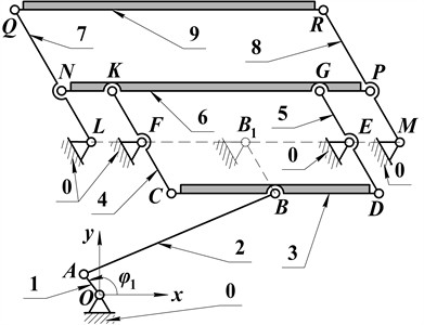
The kinematic diagram shown in Fig. 2 illustrates the planar mechanical system that governs the motion of the three-tray shaking conveyor, simplifying its physical components into interconnected links and joints for motion analysis. The symbol “0” represents the stationary machine frame (physical component 1 in Fig. 1), to which all fixed pivot points (O, L, F, E, M) are anchored. The system’s motion originates from the input link “1” (crank OA), representing the drive mechanism (physical component 6 in Fig. 1). The crank rotates around the fixed pivot O, with point A being the crankpin, and its position is defined by the angle .
The actuation and guidance of the lower conveying tray (physical component 3 in Fig. 1), represented by the rigid body line segment CBD (labeled “3” in the diagram of Fig. 2), is achieved through a specific set of linkages. The connecting rod “2” (link AB) transmits the rotary motion of the crank “1” into an oscillatory (shaking) motion by linking the crankpin A to hinge B on this lower tray. The motion of the lower tray “3” is further constrained and guided by two additional links that pivot on the frame “0”: one connecting the hinge C on the tray to the fixed pivot F, and another connecting the hinge D on the tray to the fixed pivot E. These guiding links ensure that the lower tray follows a precisely defined oscillatory (shaking) path.
The intermediate conveying and screening tray (physical component 4 in Fig. 1), depicted as the rigid body line segment NKGP (labeled “6” in the diagram of Fig. 2), derives its plane-parallel motion from its connections to both the lower and, indirectly, the upper trays. Specifically, its movement is actuated by links that form part of the “system of beams 7” in the physical design (see Fig. 1). Link “4” (link CK) connects the hinge C on the lower tray “3” to the hinge K on the intermediate tray “6”, while the link “5” (link DG) connects the hinge D on the lower tray “3” to the hinge G on the intermediate tray “6”. Through these two links, the oscillatory motion of the lower tray is transferred to the intermediate tray.
The upper conveying and screening tray (physical component 5 in Fig. 1), represented by the rigid body line segment QR (labeled “9” in the diagram of Fig. 2), is also guided by the links pivoting on the frame and actuated through its connection to the intermediate tray. Its guidance is provided by a link connecting the hinge Q on the tray to the fixed pivot L on the frame, and another link connecting the hinge R on the tray to the fixed pivot M on the frame. The actuation of this upper tray is achieved via links that are part of the “system of beams 8” in the physical machine design (see Fig. 1). Link “7” (link QN) connects the hinge Q on the upper tray “9” to the hinge N on the intermediate tray “6”, and the link “8” connects the hinge R on the upper tray “9” to the hinge P on the intermediate tray “6”. These connections mean the upper tray’s motion is determined by the already moving intermediate tray, and, in turn, influences the intermediate tray’s motion due to the guided constraints of the upper tray.
Overall, the kinematic diagram (Fig. 2) reveals a sophisticated multi-loop linkage mechanism where the motions of the intermediate and upper trays are intricately coupled, depending significantly on the motion of the lower tray and the precise geometry of all interconnecting links. This coupling allows for the generation of plane-parallel motion profiles for each individual tray. The intermediate tray, for instance, is influenced by connections at multiple points (K and G from the lower tray, and N and P from the upper tray), which dictates its stability and oscillatory characteristics. Each tray undergoes a guided oscillation, with the guiding links defining the general path and the driving links determining the timing and amplitude. In general, the diagram shown in Fig. 2 forms the essential foundation for detailed kinematic analysis, including displacement, velocity, and acceleration of each tray, which is crucial for subsequent dynamic analysis of forces and torques within the conveyor system.
The coordinates of the hinge A of the crank can be determined as follows:
where is the crank’s length.
Point B simultaneously lies on a circle centered at point A with radius and on a circle centered at point with radius . Therefore, solving the system of equations:
yields up to two solutions for and , which define the physical configuration of the excitation mechanism (e.g., upper or lower branch of motion):
where and are the lengths of the corresponding rods AB and BB1; and are the coordinates of the virtual unmovable hinge .
Knowing the coordinates of the joint B, we can determine the coordinates of the joints K and Q, which define the positions and motion characteristics of the intermediate and upper conveying and screening trays, respectively:
where , , , and are the lengths of the corresponding rods KF, CF, BC, and LQ; , , , are the coordinates of the unmovable hinges F and L, respectively.
By defining the motion law of the crank and the geometric parameters of the shaking conveyor’s mechanical system, we can determine the laws of change for the coordinates of the corresponding joints B, K, and Q. By taking the first and second time derivatives of the displacement laws, we can obtain the time dependencies of the velocities and accelerations for the corresponding conveying and screening trays. Considering the significant complexity of the resulting expressions, we will not present them in this paper, but we will limit ourselves to the results of numerical modeling conducted with the Wolfram Mathematica software.
Fig. 2Kinematic diagram of the mechanical system of the shaking conveyor
3. Results and discussion
Let us further consider similar geometrical parameters of the shaking conveyor as the ones presented in [27]: ; ; (indicating that hinge points B and C are coincident in this specific design); ; ; , ; , . Subsequently, let us analyze the steady-state oscillation modes of the conveying and screening trays at a constant forced frequency of 10 Hz (or angular velocity of 62.8 rad/s). Thus, the crank’s rotation law will take the form . The simulation results for the time-dependent changes in horizontal and vertical displacements, velocities, and accelerations of the corresponding working elements of the conveyor are presented in Fig. 3.
The numerical modeling results, presented in Fig. 3, depict the kinematic behavior of the key hinges B, K, and Q, which correspond to the lower, intermediate, and upper conveying and screening trays, respectively. All motions are shown for a steady-state operation, previously indicated to be driven by a crank rotating at an angular frequency corresponding to 10 Hz. This frequency is consistent across the time-dependent plots (Fig. 3(a) and 3(b)), where approximately 5 oscillation cycles are observed within the 0.5-second timeframe (5 cycles/0.5 s = 10 Hz). The numerical modeling results provide a multifaceted view of the hinge motions, including their absolute coordinates over time (Fig. 3(a)), a detailed look at their relative oscillatory movements (Fig. 3(b)), and the planar trajectories traced by each hinge (Fig. 3(c)-(e)).
Examining the absolute coordinates in Fig. 3(a), the mean vertical positions of the hinges clearly illustrate the tiered physical arrangement of the conveyor: hinge Q (upper tray) oscillates around approximately 422-423 mm, hinge K (intermediate tray) around 245 mm, and hinge B (lower tray) around 96 mm. The oscillations around these mean values appear relatively small in this view. Fig. 3(b), which focuses on the relative (oscillatory) components, reveals more detail about these movements. The vertical oscillation of hinge Q () is the most significant, exhibiting an amplitude of approximately ±3.2 mm. Hinge K vertical oscillation () is more moderate at about ±1 mm, while hinge B () is the smallest at approximately ±0.85 mm.
Fig. 3Results of numerical modeling of the conveyor’s mechanical system motion
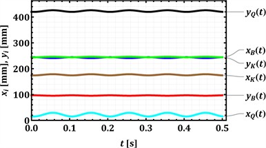
a) Absolute coordinates of the analyzed hinges
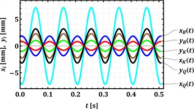
b) Relative coordinates of the analyzed hinges
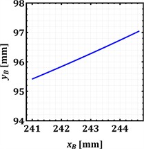
c) Motion trajectory of the hinge B
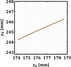
d) Motion trajectory of the hinge K
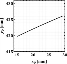
e) Motion trajectory of the hinge Q
The horizontal motions of the hinges also show distinct characteristics. From Fig. 3(a), the mean horizontal positions are approximately 22-23 mm for hinge Q (), around 177-178 mm for hinge K (), and about 241-242 mm for hinge B (). The relative coordinate plot (Fig. 3(b)) indicates that the horizontal oscillation amplitude for hinge Q () is about ±7.25 mm. For hinge K (), the horizontal amplitude is approximately ±2.3 mm, almost twice larger than its vertical amplitude. Hinge B () shows a horizontal oscillation amplitude of about ±1.85 mm. Notably, for all the hinges (B, K, Q), the corresponding horizontal (, , ) and vertical (, , ) oscillations appear to be roughly in phase, peaking at similar times.
The motion trajectories plotted in Fig. 3(c), 3(d), and 3(e) illustrate the path of each hinge in the vertical plane during their oscillation. All three hinges (B, K, and Q) trace nearly straight, inclined lines. For hinge B (Fig. 3(c)), the horizontal displacement () spans approximately 3.7 mm, while the vertical displacement () is about 1.7 mm, resulting in a positive slope of about 25°. Hinge K (Fig. 3(d)) shows a similar trajectory with 4.6 mm and 2 mm, yielding a slope of approximately 25°. Hinge Q (Fig. 3(e)) exhibits the largest trajectory, with 14.5 mm and 6.4 mm, and a corresponding positive slope of about 25°. These near-linear trajectories indicate a strong in-phase correlation between the horizontal and vertical components of motion for each hinge. While elliptical paths are often typical for vibratory conveyors to optimize material throw, these linear paths suggest a specific design choice, which can be represented as the principal axis of a very narrow ellipse.
Collectively, these simulation results highlight a well-defined, periodic kinematic behavior for the conveyor’s key hinges. The differences in oscillation amplitudes, with the upper tray’s hinge Q showing the largest displacement, suggest its primary role in material agitation and initial processing. The inclined linear motion profile common to all analyzed hinges, characterized by simultaneous positive displacements in both horizontal () and vertical () directions (and vice-versa), would impart a specific lifting and throwing action to the material, facilitating both conveying along the trays and the screening processes. The distinct kinematic characteristics of each tray, as indicated by their respective hinge motions, are crucial for the overall efficiency of the multi-stage conveying and screening operations.
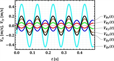
The numerical modeling results, as illustrated in Fig. 4, offer a detailed view into the time-dependent velocities (Fig. 4(a)) and accelerations (Fig. 4(b)) of the key hinges B, K, and Q. These hinges are kinematically representative of the lower, intermediate, and upper conveying and screening trays of the shaking conveyor, respectively. The analysis covers a 0.5-second period of the machine’s steady-state operation, which is driven by a crank mechanism rotating at a frequency of 10 Hz. This operational frequency is clearly reflected in the sinusoidal nature of all plotted kinematic parameters.
Examining the velocity profiles in Fig. 4(a), it is evident that all horizontal () and vertical () velocity components for each hinge follow a harmonic, sinusoidal pattern. For hinge Q, associated with the upper tray, the vertical velocity component () exhibits the highest peak magnitude, reaching approximately ±0.2 m/s, while its horizontal counterpart () peaks at around ±0.45 m/s. These two velocity components for hinge Q appear to be largely in phase. Hinge K, representing the intermediate tray, shows more moderate peak velocities: its horizontal () and vertical () components reach approximately ±0.15 m/s and ±0.07 m/s, respectively, and also seem to be in phase. Finally, hinge B, corresponding to the lower tray, displays the smallest vertical peak velocity () at about ±0.05 m/s, while its horizontal peak velocity () is around ±0.12 m/s; these components also maintain an in-phase relationship. The observed magnitudes of these peak velocities directly correlate with the displacement amplitudes previously discussed, confirming that hinge Q undergoes the most significant motion.
Fig. 4Time dependencies of the analyzed hinges’ velocities and accelerations
a) Dependencies of velocities of the hinges
b) Dependencies of accelerations of the hinges
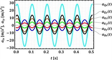
The acceleration profiles, depicted in Fig. 4(b), similarly show sinusoidal patterns for both horizontal () and vertical () components, phase-shifted by 90 degrees relative to their corresponding velocities. Hinge Q again demonstrates the most extreme values, with its horizontal acceleration () reaching a substantial peak magnitude of approximately ±28 m/s2 (roughly 3 g), and its vertical acceleration () peaking at about ±12 m/s2. The acceleration components for hinge Q also appear to be generally in phase with each other. For hinge K, the peak magnitudes for horizontal () and vertical () accelerations are around ±9 m/s2 and ±4 m/s2, respectively. Hinge B experiences peak vertical acceleration () of approximately ±3 m/s2 and peak horizontal acceleration () of about ±7 m/s2. As with displacements and velocities, hinge Q experiences the highest accelerations.
These velocity and acceleration characteristics have significant implications for the conveyor’s dynamic behavior and its interaction with the material being processed. The considerable vertical accelerations, especially the near 1.3 g experienced by the upper tray via hinge Q, indicate a motion profile capable of effectively lifting material from the tray surface. This “throwing” action is crucial for material bed stratification, enabling finer particles to reach the screen mesh, and for propelling material forward. The inertial forces generated by these high accelerations are substantial, impacting not only the material’s trajectory and screening efficiency but also imposing dynamic loads on the conveyor’s structural components. Consequently, the robust design of the trays, linkages, and particularly the vibration isolators is paramount to withstand these operational forces and to mitigate the transmission of vibrations to the surrounding environment. Furthermore, these kinematic results are fundamental for any subsequent dynamic balancing efforts and for estimating the energy consumption of the system.
4. Conclusions
The paper presented a detailed kinematic analysis of a novel shaking conveyor equipped with three interconnected transporting and screening trays. A comprehensive mathematical model of the multi-loop linkage mechanism was developed, enabling the determination of the displacement, velocity, and acceleration characteristics of key hinges representing each tray. Numerical modeling, conducted for a steady-state operational frequency of 10 Hz, successfully characterized the complex motion profiles, revealing distinct amplitudes and near-linear inclined trajectories for each tray. Notably, the upper tray exhibited the most significant displacements, velocities, and vertical accelerations, reaching values approaching 3 g (in the horizontal direction) and 1.3 g (in the vertical one).
The practical value of these findings is substantial for the design, optimization, and operation of such multi-functional vibratory equipment. The detailed kinematic data, particularly the velocity and acceleration profiles, provide critical insights into the material-tray interaction. The significant vertical accelerations achieved, especially by the upper tray, indicate a motion profile conducive to effective material lifting, “throwing”, and bed stratification, which are essential for efficient screening and forward conveyance. Understanding these kinematic characteristics allows engineers to predict and enhance material processing efficiency. Furthermore, the calculated accelerations are fundamental for estimating the inertial forces acting on the material and the machine’s structural components. This information is paramount for ensuring the robust mechanical design of the trays and linkages to withstand dynamic operational loads and for designing effective vibration isolation systems to minimize transmission to the surroundings. The kinematic model also serves as a foundational tool for future dynamic balancing efforts and for preliminary estimations of energy consumption.
The presented research opens avenues for several promising future investigations. A full dynamic analysis, incorporating mass properties and driving forces, would allow for the determination of joint reaction forces, motor torque requirements, and overall power consumption, providing a more complete understanding of the machine’s operational efficiency. Experimental validation of the developed kinematic and subsequent dynamic models using a physical prototype is crucial to confirm the accuracy of the theoretical predictions. Further studies could focus on optimizing the geometric parameters of the linkage system and the operational speed of the crank to tailor the motion characteristics for specific materials and desired processing outcomes (e.g., maximizing throughput or separation efficiency). Integrating the derived kinematic data with Discrete Element Method (DEM) simulations could offer deeper insights into the granular material flow and interaction with the vibrating trays. Finally, investigations into the wear, fatigue life of critical components, and the development of advanced control strategies to adapt the conveyor’s operation to varying load conditions would further enhance the practical applicability and performance of such multi-tray shaking conveyors.
References
-
S. Kilikevičius, K. Liutkauskienė, R. Česnavičius, A. Keršys, and R. Makaras, “Investigation of the motion characteristics of parts on a platform subjected to planar oscillations,” Applied Sciences, Vol. 13, No. 17, p. 9576, Aug. 2023, https://doi.org/10.3390/app13179576
-
R. El Banna, K. Liutkauskienė, V. Lukoševičius, A. Fedaravičius, and S. Kilikevičius, “Transportation of objects on an inclined plane oscillating in the longitudinal direction applying dynamic dry friction manipulations,” Applied Sciences, Vol. 14, No. 11, p. 4474, May 2024, https://doi.org/10.3390/app14114474
-
Y. Guo, Y. Fang, X. Li, D. Jin, and H. Liu, “Simulation of screening characterization of double-deck vibrating screen of slurry TBM tunnelling using integrated CFD-DEM-FEM,” Tunnelling and Underground Space Technology, Vol. 158, p. 106399, Apr. 2025, https://doi.org/10.1016/j.tust.2025.106399
-
D. Lin et al., “A rigid-flexible coupled dynamic model of a flip-flow vibrating screen considering the effects of processed materials,” Powder Technology, Vol. 427, p. 118753, Sep. 2023, https://doi.org/10.1016/j.powtec.2023.118753
-
D. Lin, X. Wang, N. Xu, W. Zuo, and Z. Liang, “A method for stabilizing the vibration amplitude of a flip-flow vibrating screen using piecewise linear springs,” Minerals, Vol. 14, No. 4, p. 406, Apr. 2024, https://doi.org/10.3390/min14040406
-
W. Żmuda and P. Czubak, “Operation of a new single-vibrator conveyor on the falling slope of the second resonance,” Transport Problems, Vol. 18, No. 4, pp. 223–232, Dec. 2023, https://doi.org/10.20858/tp.2023.18.4.18
-
V. Korendiy, V. Gursky, P. Krot, and O. Kachur, “Dynamic analysis of three-mass vibratory system with twin crank-slider excitation mechanism,” Vibrations in Physical Systems, Vol. 34, No. 2, pp. 1–9, Jan. 2023, https://doi.org/10.21008/j.0860-6897.2023.2.26
-
V. Korendiy, O. Kachur, I. Hurey, R. Predko, R. Palash, and O. Havrylchenko, “Modelling and experimental investigation of the vibratory conveyor operating conditions,” Vibroengineering Procedia, Vol. 47, pp. 1–7, Dec. 2022, https://doi.org/10.21595/vp.2022.23057
-
O. Kachur, V. Korendiy, O. Lanets, R. Kachmar, I. Nazar, and V. Heletiy, “Dynamics of a vibratory screening conveyor equipped with a controllable centrifugal exciter,” Vibroengineering Procedia, Vol. 48, pp. 8–14, Feb. 2023, https://doi.org/10.21595/vp.2023.23175
-
V. Despotović, D. Urukalo, M. R. Lečić, and A. Ćosić, “Mathematical modeling of resonant linear vibratory conveyor with electromagnetic excitation: simulations and experimental results,” Applied Mathematical Modelling, Vol. 41, pp. 1–24, Jan. 2017, https://doi.org/10.1016/j.apm.2016.09.010
-
G. Filimonikhin, V. Pirogov, M. Hodunko, R. Kisilov, and V. Mazhara, “The dynamics of a resonance single-mass vibratory machine with a vibration exciter of targeted action that operates on the Sommerfeld effect,” Eastern-European Journal of Enterprise Technologies, Vol. 3, No. 7(111), pp. 51–58, Jun. 2021, https://doi.org/10.15587/1729-4061.2021.233960
-
R. Belotti, D. Richiedei, I. Tamellin, and A. Trevisani, “Response optimization of underactuated vibration generators through dynamic structural modification and shaping of the excitation forces,” The International Journal of Advanced Manufacturing Technology, Vol. 112, No. 1-2, pp. 505–524, Nov. 2020, https://doi.org/10.1007/s00170-020-06083-2
-
J. Bettega, D. Richiedei, I. Tamellin, and A. Trevisani, “Integrated inverse dynamics and optimized mechanical design in underactuated linear vibratory feeders under periodic excitation,” Journal of Vibration Engineering and Technologies, Vol. 11, No. 6, pp. 2531–2546, Mar. 2023, https://doi.org/10.1007/s42417-023-00950-4
-
V. Korendiy, O. Kachur, V. Zakharov, and I. Kuzio, “Studying the dynamics of a vibratory finishing machine providing the single-sided lapping and polishing of flat surfaces,” Engineering Proceedings, Vol. 24, No. 1, Sep. 2022, https://doi.org/10.3390/iecma2022-12898
-
V. Korendiy, O. Kachur, V. Gurskyi, and P. Krot, “Studying the influence of the impact gap value on the average translational speed of the wheeled vibration-driven robot,” Engineering Proceedings, Vol. 24, No. 1, p. 25, Sep. 2022, https://doi.org/10.3390/iecma2022-12897
-
M.-B. Tătaru, A. Rus, T. Vesselényi, M. Raţiu, and I. Ţarcă, “Synthesis and functional optimization of a vibratory machine with a parallel mechanism structure,” Applied Sciences, Vol. 15, No. 9, p. 4910, Apr. 2025, https://doi.org/10.3390/app15094910
-
M. Buzzoni, M. Battarra, E. Mucchi, and G. Dalpiaz, “Motion analysis of a linear vibratory feeder: Dynamic modeling and experimental verification,” Mechanism and Machine Theory, Vol. 114, pp. 98–110, Aug. 2017, https://doi.org/10.1016/j.mechmachtheory.2017.04.006
-
V. X. Nguyen and N. S. Golikov, “Analysis of material particle motion and optimizing parameters of vibration of two-mass GZS vibratory feeder,” in Journal of Physics: Conference Series, Vol. 1015, No. 5, p. 052020, May 2018, https://doi.org/10.1088/1742-6596/1015/5/052020
-
Z. Algazy, “The substantiating of the dynamic parameters of the shaking conveyor mechanism,” Vibroengineering Procedia, Vol. 5, pp. 15–20, 2015.
-
Y. Yeleukulov et al., “Mechanical analysis of vibratory conveyor mechanism,” in MATEC Web of Conferences, Vol. 226, p. 01019, Nov. 2018, https://doi.org/10.1051/matecconf/201822601019
-
A. Zhauyt, K. Alipbayev, A. Aden, A. Orazaliyeva, and G. Bikhozhayeva, “Determination of Kinematic and Dynamic Characteristics of Oscillating Conveyor Mechanism,” Applied Sciences, Vol. 15, No. 3, p. 1676, Feb. 2025, https://doi.org/10.3390/app15031676
-
Y. Umbetkulov et al., “Dynamic force analysis of a six-link planar mechanism,” in MATEC Web of Conferences, Vol. 251, p. 04028, Dec. 2018, https://doi.org/10.1051/matecconf/201825104028
-
H. Li, C. Liu, E. Zhou, and L. Shen, “Research on dynamic and vibration behaviors of a flip-flow screen with crankshaft-link structure,” Journal of Vibroengineering, Vol. 24, No. 5, pp. 836–847, Aug. 2022, https://doi.org/10.21595/jve.2022.22455
-
G. F. Alışverişçi, “The nonlinear behavior of vibrational conveyers with single‐mass crank‐and‐rod exciters,” Mathematical Problems in Engineering, Vol. 2012, No. 1, p. 53418, Oct. 2012, https://doi.org/10.1155/2012/534189
-
G. F. Alişverişçi, “The nonlinear analysis of vibrational conveyers with non-ideal crank-and-rod exciters,” Applied Mechanics and Materials, Vol. 706, pp. 44–53, Dec. 2014, https://doi.org/10.4028/www.scientific.net/amm.706.44
-
O. Lanets, O. Kachur, V. Korendiy, and V. Lozynskyy, “Controllable crank mechanism for exciting oscillations of vibratory equipment,” in Lecture Notes in Mechanical Engineering, Cham: Springer International Publishing, 2021, pp. 43–52, https://doi.org/10.1007/978-3-030-77823-1_5
-
V. Korendiy, O. Kachur, and P. Dmyterko, “Kinematic analysis of an oscillatory system of a shaking conveyor-separator,” in Lecture Notes in Mechanical Engineering, Cham: Springer International Publishing, 2021, pp. 592–601, https://doi.org/10.1007/978-3-030-91327-4_57
-
O. Kachur and V. Korendiy, “Dynamic behavior of vibratory screening conveyor equipped with crank-type exciter,” in Lecture Notes in Mechanical Engineering, Cham: Springer Nature Switzerland, 2023, pp. 44–53, https://doi.org/10.1007/978-3-031-32774-2_5
About this article

The authors have not disclosed any funding.
The datasets generated during and/or analyzed during the current study are available from the corresponding author on reasonable request.
