Abstract
In this paper is studied a vibratory conveyor that is placed on an elastic base. Using the closed contours method it was determined the system that needs to be solved to obtain graphical representation for the generalized coordinates determining the position of the mechanical system elements. The shaking conveyor represents the chase hanged or supported to the fixed section. The chase commits oscillating motions hereupon the cargo which is in the chase, migrates concerning to the chase. The nature of the flow and its parameters are determined by the nature of the oscillating committed by the chase. Justifying the dynamic parameters of the shaking conveyor and a study of the stress-strain state. Installation causes fluctuations fixed tray. Uniformly distributed load on the tray acts in each element of the mechanism. A proper dynamic model has been developed within MSC ADAMS software. Simulation tests have been carried out and results are discussed to validate the proposed design solution.
1. Introduction
The big application in various fields of the industry was received by the shaking conveyors applied to transportation of hot, poisonous, chemical aggressive cargoes by the supplement of complete tightness of their relocation [4], and also for transportation of the metallic cuttings damped with emulsion and oil, hot earth which has been beaten out from casting forms, small casting, foundry fusion mixture, etc. The shaking conveyor represents the chase hanged or supported to the fixed section. The chase commits oscillating motions hereupon the cargo which is in the chase, migrates concerning to the chase [5-8]. The nature of the flow and its parameters are determined by the nature of the oscillating committed by the chase. Shaking conveyors on the conditions of the chase flow and nature of cargo movement are subdivided on inertial (with variable and constant stress of cargo to the chase) in which [9] cargo under the influence of inertia force glides on the chase, and on vibrating in which cargo tears off the chase and migrates along the chase. The vibrating conveyors [1-3] are widely applied owing to a number of advantages in these latter days. The questions of the kinematic and dynamic study of the vibrating feeder intended for dosing of the fusion mixture loading of the melting furnaces of foundry production are considered in the presented work [11-15]. The principle of operation of the vibrating conveyor is described, and it is devoted the kinematic analysis of the action. The differential equation of the link move of the reduction of the vibrating conveyor is considered in the difference method (the approximate method) solutions of the equation of move of the vibrating conveyor is resulted [10]. It is devoted to the analysis of the equations solutions of conveyor move. Here tables of the results and relocation drawing and velocity of the leading link depending on time are resulted.
2. Materials and methods
2.1. Differential equations of the link move of the reduction of the vibrating conveyor
It is the action of the III class. The crew ВЕD basic crew from which there are three leads FЕ, АВ, GD. The link ОА is a leading link.
This action has one axis of motion, therefore relocation, velocities and speed-up of the driven link and action dots are functions of the relocation, velocities and speed-up of the leading link. Therefore we will find analytical dependences between relocations, velocities of the driven links and leading link. As the leading link enters into the rotational pair with the console we set function:
Fig. 1Kinematic scheme of the shaking conveyor
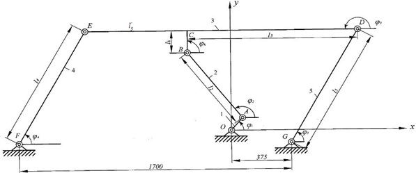
Table 1The action has following performances
No. | Links | ||||
1 | 2 | 3 | 4 | 5 | |
Mass, kg | 30 | 65 | 1160 | 59 | 59 |
Length units, mm | 60 | 430 | 1100 | 440 | 440 |
By the solution of the action move problem with one degree of freedom we will use the equation of the action move of the engine aggregate:
It is known to us dependence and . We determine the resulted moment of resistance forces from power equalling of the resulted moment of force resistance and the sum of powers of the moments [5] of resistance forces of operating in links , , , :
Let’s find resulted moment of the flywheel actions from equalling condition of kinematic energy of reduction link to the kinematic energy sum of all links of the action:
We determine inertia moments of the first, second, fourth and fifth links.
We differentiate the resulted inertia moment on . For this purpose we substituted all above found values in the equation:
The move equation of the reduction link of the action looks like:
For solution of the Eq. (3) there are following initial conditions: at 0, 0, 60°.
2.2. The approximate method of the equation solutions of the vibrating conveyor
For constructing on the piece of the approximate solution of the move Eq. (3), we copy it in the following kind:
where:
3. Results and discussion
A proper dynamic model has been developed within MSC ADAMS software to provide information on the feasibility of the proposed design solution. Simulation tests have been carried out and results are discussed for validating the proposed design and characterizing its operation.
Fig. 2Six bar linkage motion simulation in MD Adams
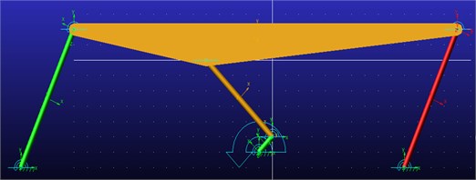
Fig. 3Computed plot of the force and momentum joint 1
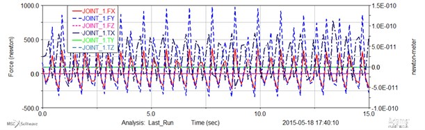
Fig. 4Computed plot of the force and momentum joint 2
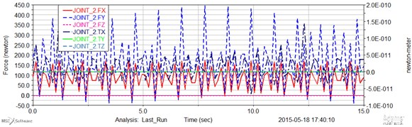
Fig. 5Computed plot of the force and momentum joint 3
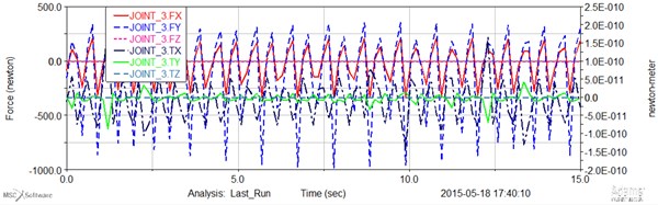
Fig. 6Computed plot of the force and momentum joint 7
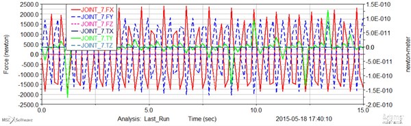
Fig. 7Computed plot of the force and momentum joint 8
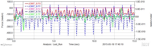
Fig. 8Computed plot of the force and momentum joint 9
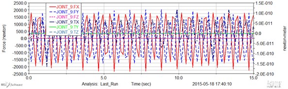
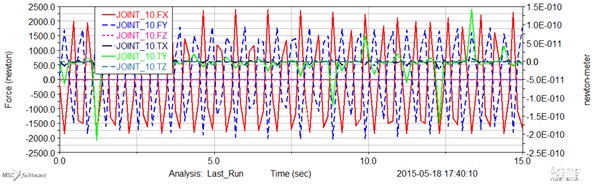
Fig. 9Computed plot of the force and momentum joint 10
4. Conclusions
1) Formulas for the position determination and velocity of conducted links depending on position and velocity of the leading link are received.
2) The differential equations of the link move of the action reduction are received.
3) On the basis of the profiles variation analysis of the angular rate of the leading link it is possible to make the following concluding:
– with the growth of the starting driving moment middle angulator of the action grows;
– with reduction of the starting driving moment middle angular rate of the action is decays;
– with coefficient increase , grows.
4) The basis of the program MSC Adams software investigated the kinetic energy and translational momentum of each link mechanism with results and calculations.
References
-
Andrea V., Nicolae U., Loana A. M. Determining the maximal relative motion speed considering the influence of two parameters, using a new optimization method. ACTA Technica Napocensis, Vol. 4, Issue 55, 2012, p. 949-954.
-
Wyk A. J., Snyman J. A., Heyns P. S. Optimization of a vibratory conveyor for reduced support reaction force. N&O Journal, Vol. 1, Issue 10, 1994, p. 12-17.
-
Andrea V., Nicolae U., Loana A. M. Contribution to the optimization of relative motion on a vibrating conveyor. ACTA Technica Napocensis, Vol. 2, Issue 55, 2012, p. 519-522.
-
Chu Yiqing, Li Cuiying Helical vibratory conveyors for bulk materials. Bulk Solid Handling, Vol. 1, Issue 7, 1987, p. 103-112.
-
Dinu I. S., Miorita U., Nicu U., Mihai B. Computer model for sieves vibrations analysis, using an algorithm based on the false-position method. American Journal of Applied Sciences, Vol. 6, Issue 1, 2009, p. 48-56.
-
Dülger L. C., Erdoğan H., Kütük M. E. Matlab’s GA and optimization toolbox: a four-bar mechanism application. International Journal of Intelligent Systems and Applications in Engineering, Vol. 2, Issue 1, p. 10-15.
-
Cabrera J. A., Simon A., Prado M. Optimal synthesis of mechanisms with genetic algorithms. Mechanism and Machine Theory, Vol. 37, 2002, p. 1165-1177.
-
Bulatovic R. R., Djordjevic S. R. Optimal synthesis of a four bar linkage by method of controlled deviation. Journal of Theoretical and Applied Mechanics, Vol. 1, Issue 31, 2004, p. 264-280.
-
Laribi M. A., Mlika A., Romdhane L., Zeghloul S. A combined genetic algorithm-fuzzy logic method (GAFL) in mechanisms synthesis. Mechanism and Machine Theory, Vol. 39, 2004, p. 717-735.
-
Penunuri F., Escalante R. P., Villanueva C., Pech-Oy D. Optimum synthesis of mechanism for single and hybrid task using differential evolution. Mechanism and Machine Theory, Vol. 10, Issue 46, 2011, p. 1335-1349.
-
Xie J., Chen Y. Application back propagation neural network to synthesis of whole cycle motion generation mechanism. 12th IFToMM World Congress-Besancon France, June, 2007, p. 18-21.
-
Liu Y., McPhee J. Automated kinematic synthesis of planar mechanisms with revolute joints. Mechanics Based Design of Structures and Machines, Vol. 35, 2007, p. 405-445.
-
Erkaya S., Uzmay I. A Neural-Genetic (NN-GA) approach for optimizing mechanisms having joints with clearance. Multibody System Dynamics, Vol. 20, 2008, p. 69-83.
-
Zadeh N. N., Felezi M., Jamali A., Ganji M. Pare to optimal synthesis of four-bar mechanisms for path generation. Mechanism and Machine Theory, Vol. 22, 2009, p. 180-191.
-
Archaryya S. K., Mandal M. Performance of EAs for four-bar linkage synthesis. Mechanism and Machine Theory, Vol. 44, 2009, p. 1784-1794.
About this article

The first author likes to acknowledge JSC Center of Republic of Kazakhstan for supporting his Ph.D. study and research at LARM in the University of Bielsko-Biala in Poland, in the academic year 2014-2015.
