Abstract
Based on coupling algorithm of Lagrangian finite element method and Eulerian method (CEL), and rotating band as Eulerian section and other parts as Lagrangian section, the dynamic model of a projectile and rifled barrel coupled system is established. It can remedy the weakness of Lagrangian finite element method (FEM) for applications involving extreme deformation. Then, using CEL method and FEM, the numerical simulations are performed respectively. The curves of projectile motions, the dynamic engraving resistances are obtained, compared and analyzed. The results show that, CEL method can perform well under extreme deformation. What is more, the accuracy and the efficiency are improved remarkably. This provides better method for the future studies of the engraving process of large caliber gun and even for the studies of initial disturbance of projectile with engraving process being considered.
1. Introduction
Transient experience, high temperature, intensive impact, high-speed friction and large deformation usually complicate analysis of rotating band engraving process under practical firing conditions gravely. The development of guns with features of high muzzle velocities, large firing range, high firing rate, and high firing accuracy requires dynamic analysis of rotating band engraving process. Classical theoretical research summarized in Ref. [1] overly simplified the computations of the plastic deformation and material failure of the rotating band due to their limited numerical tools. The research work about influences of different bore structures on engraving process reported by Ref. [2] and the study on influences of bore structures on gun’s interior ballistic performances in Ref. [3] were both carried out by utilizing explicit finite element methods and had obtained valuable results. But in these applications, traditional Lagrangian elements become highly distorted and lose accuracy.
Based on what we have discussed above, a numerical method which is called CEL will be mentioned in this paper. CEL analyses are effective for applications involving extreme deformation [4]. This method will be used in the study of engraving process in this paper.
2. Mechanical calculation model
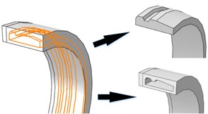
2.1. Engraving process
Initially, the projectile is loaded into the chamber and positioned to its seizing-bore location before firing. When firing, propellant gas pressure in the chamber raises and the projectile begins to move. As propellant gas pressure increases, the rotating band undergoes plastic deformation and is engraved into the rifles. Eventually, the engraving process ends after the rotating band together with its extension part is engraved into the rifles completely.
2.2. Basic assumptions
To simplify the calculation model and catch the main characteristics of the engraving process, several basic assumptions are drawn as follows: 1) The rotating band boss was initially in contact with the forcing cone section of the gun tube. The initial stress and deformation of the rotating band were neglected. 2) The gun tube was supposed to be static. The dynamic unbalance of the projectile was ignored. 3) We ignored the effect of thermal stress. The heat generated by contact was also considered to be negligible.
2.3. Finite elements and contact algorithm
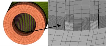
In the model which are shown in Fig. 1 is meshed by the Hypermesh software. Numerical simulations are carried out using ABAQUS. There is a total of 582,830 elements, and the rotating band has 479,412 elements. This model will be used during the system study except CEL analyses. In CEL analyses, as an Eulerian section, the rotating band must be built in ABAQUS. The contact between the rotating band and the inner wall of the tube is modelled using a *GENERIAL CONTACT algorithm available in ABAQUS. The finite element models are solved by utilizing the explicit integration algorithm.
Fig. 1Mesh of finite element model
2.4. Material model
The tube and the projectile body are made of steel. The rotating band is made of CuZn10 brass. The constitutive relation of the Johnson-Cook model [5] and Johnson-Cook failure model [6] have been chosen to represent its behavior, which is expressed by Eqs. (1), (2):
where and are the effective plastic strain and the effective plastic strain rate respectively, is the reference strain rate, , , are respectively the actual temperature, room temperature and the melting temperature in the absolute scale, and , , , , are material constants. - are the material failure constants, is the stress triaxiality defined by in which is the hydrostatic stress and is the equivalent von Mises stress.
The damage accumulation has the basic form expressed by Eq. (3):
where is the damage parameter to a material element. Failure occurs when 1, and in the finite element simulations element erosion is used to remove elements that have reached the critical damage. The material parameters of the Johnson-Cook constitutive and failure model for CuZn10 brass are reported in Table 1.
Table 1Material constants for CuZn10 brass
Quantities | Constants | Quantities | Constants | Quantities | Constants |
/ Kg/m3 | 8944 | 0.025 | 0.54 | ||
/ MPa | 121000 | 0.31 | 4.89 | ||
0.33 | 1.09 | 3.031 | |||
/ MPa | 90 | MT / K | 1355 | 0.014 | |
/ MPa | 292 | TT / K | 293 | 1.12 |
2.5. Loads and boundary conditions
The projectile base pressure drives the projectile and it is the main load of the system. The projectile base pressure is obtained by live firing. According to the model assumptions previously stated in Section 2.2, all of the degrees of freedom of the tube are constrained.
3. CEL method
Lagrangian elements are always 100 % full of a single material, so the material boundary coincides with an element boundary. By contrast, in an Eulerian analysis nodes are fixed in space, and material flows through elements that do not deform [7]. Eulerian elements may not always be 100 % full of material, many may be partially or completely void. The Eulerian material boundary must, therefore, be computed during each time increment and generally does not correspond to an element boundary. The Eulerian mesh is typically a simple rectangular grid of elements constructed to extend well beyond the Eulerian material boundaries, giving the material space to move and deform. The different features of Lagrangian algorithm and Eulerian algorithm have been shown by Fig. 2 [8].
Fig. 2Lagrangian and Eulerian algorithm
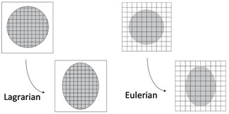
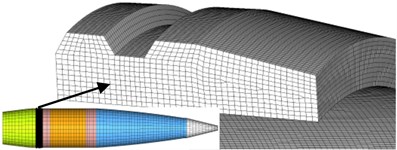
Fig. 3The rotating band of Eulerian analyses
CEL method is developed on the advantages of Lagrangian method and Eulerian method. The Eulerian-Lagrangian contact formulation is based on an enhanced immersed boundary method. In this method the Lagrangian structure occupies void regions inside the Eulerian mesh. In ABAQUS, the contact algorithm automatically computes and tracks the interface between the Lagrangian structure and the Eulerian materials [9].
CEL method applies explicit dynamic methods of which are based on the central difference criterion to solve the nonlinear differential equations:
where , , indicate displacement, velocity, and acceleration of freedom respectively. is the time increment. is the moment of increment .
4. Results and analysis
4.1. Deformation process
As it has been mentioned in Section 2.2, the Eulerian part must be built in ABAQUS, and the model has been given by Fig. 3. In this case, there is a total of 695674 elements in the model, and 592256 elements among the model belong to Eulerian part. But the time cost of this simulation is just 23.5 hours. Fig. 4 shows us the evolution of rotating band during engraving process using CEL method. This process finished around 6.7 ms after it started.
Through observation, it is clear that the material of the band can flow inside the Eulerian mesh freely, so it can reflect the plastic flow process of the band more clearly while the band is sheared by the internal wall of gun tube. The deformation and flow of the material is obtained. The detail of engraving process is, when the projectile has been loaded, the rotating band kept in contact with the inner wall of the tube closely. Once the projectile base pressure increases to a certain value, the projectile begins to move. The diameter of forcing cone is decreasing as the projectile going forward, so the front end of the rotating band begins to be deformed. The elastic and plastic deformation of the rotating band begin to happen, and the groove on the rotating band starts to be filled by the part of the rotating band which has been pushed to backward. As the engraving process keeps on going, the parts of rotating band of which corresponding with rifling lands are forced to be extruded and sheared. Finally, the rotating band is engraved by the rifling lands, the rotating band and the interior wall of the tube are fitted closely. The engraving process finished.
Given that FEM has been used widely in engraving simulation. In this study, the FEM-based simulation is used to verify and compare the results from the proposed method in this paper. The whole process costs around 6.9 ms. Fig. 5 is the evolution of von Mises stress of rotation band.
Fig. 4Evolution of von Mises stress for rotation band under CEL method
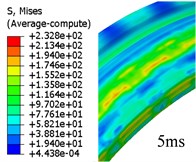
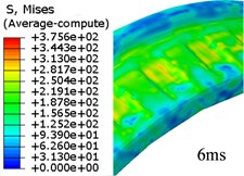
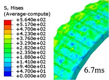
Fig. 5Evolution of von Mises stress for rotation band under FEM
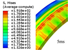
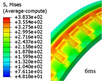
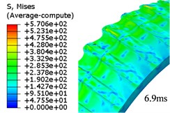
Fig. 6The deleted elements
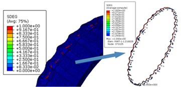
Because the traditional finite element mesh can cause simulation termination in the event of large deformation, the plastic strain accumulation criterion which is mentioned in Section 2.4 was introduced to delete the failed elements. The elements of which forced to deleted are shown in Fig. 6. In ABAQUS, one element is failed upon its parameter SDEG reaches 1. Totally 1232 elements, 0.257 % of the total elements of the rotating band, have been forced to be deleted due to the extreme distortion. These deleted elements interior attributes are also deleted. Therefore, it inevitably caused energy loss. Although the energy is small, we cannot draw the conclusion that the energy will not affect the kinematics of the projectile. From Fig. 6, it can be seen that the failure of the rotating band elements occurs more often near the rear of the band. This shows the fact that during the engraving process, the material of rotating band is forced to flow to the rear at first, then, the element failure happens as the rotating band keeps moving forward.
4.2. Projectile motion
The displacement time curves, velocity time curves and acceleration time curves of the projectile which are obtained from the simulation using FEM method, CEL method are given by Figs. 7-9. Through the comparison, although the numerical algorithms vary, the displacement, velocity and acceleration curves of these three simulations are basically the same.
A research on a 76 mm gun conducted by one former Soviet weapon expert [11] shows that the velocity of the projectile has reached 10 % of the muzzle velocity upon the band engraved in rifles completely. The instantaneous velocities of projectile when engraving process is finished are 7.9 % (FEM), 10.28 % (CEL) of its muzzle velocity respectively in these simulations which are basically consistent with the results above.
Fig. 7Displacement-time curves
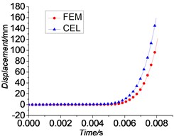
Fig. 8Velocity-time curves
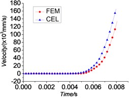
Fig. 9Acceleration-time curves
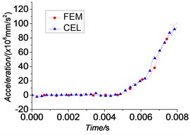
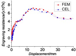
Fig. 10Engraving resistance
4.3. Dynamic engraving resistance
The dynamic engraving resistance consists of resistance due to plastic deformation and friction force. Calculating them separately is known to be intractable, so instead we compute the dynamic engraving resistance through the differential Equation of the motion of the projectile, which is given by Eq. (5):
where is the area of the projectile base, is the projectile base pressure, is the mass of the projectile, and is the acceleration of the projectile.
Fig. 10 gives the engraving resistance versus travel distance curves. As we can see, the trend of these three curves and the peak values are basically the same. In Ref. [11], the Soviet expert also got the conclusion that when the engraving process finishes, the engraving pressure has reached 173 MPa which is 65 % of the maximum value. The results of engraving process through numerical calculations are 67.7 % (FEM), 64.83 % (CEL) of its maximum value respectively. The comparison of main parameters are summarized in Table 2. We get the law of the resistance changing through these curves: the engraving resistance increases as the rotating band is engraved deeper to its peak value and then almost maintains a constant level. Subsequently the engraving resistance decreases as the deformation of the rotating band reduces until the rotating band together with its extension part engraves into the rifles completely. Then, the resistance maintains almost a constant value that is generated by friction. These conclusions can somehow demonstrate the validity of simulations in this paper.
Table 2Comparison of main parameters
Engraving pressure at engraving completion point / Maximum pressure (%) | Velocity at engraving completion point / Muzzle velocity (%) | Time cost (h) | |
FEM | 67.7 | 7.9 | 77 |
CEL | 64.83 | 10.28 | 23.5 |
Ref. [11] | 65 | 10 | – |
5. Conclusions
In this paper, CEL method is used to simulate the issue of engraving process. We obtained laws of projectile motion and dynamic engraving resistance. The results show that CEL method can perform well when confronting extreme element distortion, and it can avoid energy loss which happens under FEM method. Its time cost is relatively low. Using this method, the engraving process is simulated more effectively and more efficiently. This will play an important role in the studies of performances of inner ballistics.
References
-
Qierbarov E. B. Interior Ballistics and Engraving Force Calculation during Engraving of Projectile. Yang Jing-Rong, translated. National Defense Industry Press, Beijing, 1997.
-
Sun H. Y., Ma J. S., Li W., et al. Influence of different bore structures on engraving process on projectile. Journal of Vibration and Shock, Vol. 30, Issue 3, 2011, p. 30-33.
-
Sun H. Y., Ma J. S., Li W., et al. Study on influence of bore structure on gun’s interior ballistic performances. Acta Armamentarii, Vol. 33, Issue 6, 2012, p. 669-675.
-
Benson D. J. Computational methods in Lagrangian and Eulerian hydrocodes. Computer Methods in Applied Mechanics and Engineering, Vol. 99, 1992, p. 235-394.
-
Johnson G. R., Cook W. H. A constitutive model and data for metals subjected to large strains, high strain rates and high temperatures. Proceedings of the 7th International Symposium on Ballistics, Vol. 21, 1983, p. 541-547.
-
Johnson G. R., Cook W. H. Fracture characteristics of three metals subjected to various strains, strain rates, temperatures and pressures. Engineering Fracture Mechanics, Vol. 21, Issue 1, 1985, p. 31-48.
-
David J. Bemson Computational Methods in Lagrangian and Eulerian Hydrocodes. University of California, San Diego, USA, 1990.
-
Qiu G., Henke S., Grabe J., et al. Application of a coupled Eulerian-Lagrangian approach on geomechanical problems involving large deformations. Computers and Geotechnics, Vol. 38, 2011, p. 30-39.
-
Benson D. J. Contact in a multi-material Eulerian finite element formulation. Computer Methods in Applied Mechanics and Engineering, Vol. 193, 2004, p. 4277-4298.
-
Sun Q. Z., Yang G. L., et al. Numerical research on rotating band engraving process of a large-caliber howitzer. Acta Armamentarii, Vol. 36, Issue 2, 2015, p. 207-213.
-
Jin Z. M. Interior Ballistics of Guns. Beijing Institute of Technology Press, Beijing, 2004.
About this article

The authors would like to acknowledge the financial supports from the State 973 Program of China (Grant No. 51319702), the National Natural Science Foundation of China (Grant No. 11172139) and the Major National Scientific Instrument and Equipment Development Project of China (2013YQ47076508).
