Abstract
Linear vibratory conveyors are common equipment to convey goods. They are used in different industries such as for example the building, mining and food industry. The systems are mainly used for the supply of bulk goods into further processing operations. The goods to be conveyed, typically requesting a heavy-duty design of the conveyor and eccentric excitation drives with relatively high torque. A supply of strong vibrations to the floor is an effect, which often is caused by vibratory conveyors. The target of this article is to determine a dynamic model, based on a two-mass absorber system, helping to avoid the transfer of vibrations to the ground. An optimum supply of goods by the same time should be ensured.
1. Introduction
Linear vibratory conveyors are mainly built to forward bulk material for the mining, building and food industry, such as rock, grit and flour. The assembly of these vibratory conveyors consists of two principal parts, the conveying element build as a conveying trough and a supporting element, build of steel elements and fixed to the ground by heavy-duty screws [1, 2]. These conveyors commonly representing one-mass systems. The disadvantage of one-mass systems is the limitation of possibilities to optimize the efficiency regarding the conveying of the goods and even more, the limitation in reducing the transmission of vibrations to the floor.
A two-mass conveyor as shown in Fig. 1 represents an alternative solution to a one-mass linear vibrating conveyor.
Fig. 1Vibratory conveyor with two masses [3]
![Vibratory conveyor with two masses [3]](https://static-01.extrica.com/articles/19066/19066-img1.jpg)
2. Applied methods
The theoretical solution is done in two steps. At first, a dynamic model is designed and then the dynamic parameters are determined.
2.1. Determination of the conveyors dynamic model
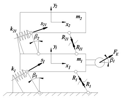
The assembly of the following two-mass vibratory conveyor consists of three principal parts, the conveying element build as a conveying trough, represented by character , the excited mass with the drive, represented by character and a supporting element, fixed to the ground. Both masses are connected by the use of springs. In this case, helical springs are chosen. The excitation of is done by an eccentric drive, installed to excite the mass 90° to the lever [4]. The springs with their particular stiffness are defined as and . The damping of the system is neglected. Mass is connected to the ground by levers under an angle , mass is connected to mass by levers under an angle . The levers enabling a defined guidance of the masses motion. Fig. 2 shows the mechanical model of this two-mass conveyor.
Fig. 2Mechanical model of the vibratory conveyor
2.2. Calculation of dynamic parameters
Based on the mechanical model shown in Fig. 2, the following equations are formed [5]:
Summing up the Eqs. (1) and (3), (2) and (4) as well as (3) and (4), the following equations can be formed:
Merging Eqs. (5) and (6), the equation can be formed as:
and after converting Eq. (8):
Splitting up the motion of and into the components, the following form can be written:
The levers guide the motion of each of the two masses between floor and mass and between mass and mass . Therefore, the coordinate vectors with the characters and can be merged and replaced by character .
Then the Eqs. (10) and (11) can be formed as:
with
After simplifying the Eqs. (12) and (13), the final equations of motion for the analyzed conveyor model are:
3. Results and discussions
The results of the above equations can be used to optimize the dynamic parameters.
3.1. Variation of the angles of the dynamic model
For the further analysis of the dynamic model, three cases are of particular interest:
– Case one with ,
– Case two with and
– Case three with .
For case one with , Eq. (15) can be converted step by step:
to the final form:
Eq. (16) is transformed by the same way into the final form:
For case two with , the equations are:
For case three with , the following equations can be formed:
3.2. Calculation of the displacement
To find the zero displacement of mass and the maximum displacement , of mass , the corresponding equations for case can be formed as:
Eq. (26) can be adjusted in a way that will become zero. For that case, the minimum transmission of forces to the floor is achieved [6, 7].
Based on this dynamical model, the minimum transmission of vibration and forces to the floor is achieved. As soon as mass remains stationary, the total excitation is passed over to the absorber mass , supplying the optimum conveying of goods [8].
4. Conclusions
In this paper, a dynamic model of a two-mass linear vibratory conveyor, conducted with the calculation of kinematic parameters for the model is determined. The result of the elaboration is a mechanical model, which can be used as base for the modification of the conveyors motion and simultaneous the elimination of vibration forces to the floor of a building. The excitation of the system is transferred to an absorber mass, which represents the conveying element and a transfer of vibrations to the ground will not take place.
General equations for the model are developed and the final equations to calculate minimum and maximum displacements of the two masses are shown.
Based on the results of the paper, parameters for the design of two-mass linear vibratory conveyors can be defined and simulated.
References
-
Harris C.M. Shock and Vibration Handbook. Fifth Edition, McGraw-Hill, New York, 2005.
-
Buja H. O. Praxishandbuch Ramm- und Vibrationstechnik. Bauwerk Verlag, Berlin, 2007.
-
Action Equipment Company, http:// http://actionconveyors.com/products/vibratory-feeders/.
-
Dresig H., Holzweißig F. Maschinendynamik 8. Auflage, Springer Verlag, Berlin, 2008.
-
Knaebel M., Jäger H., Roland MastelR. Technische Schwingungslehre, 7. Auflage. Vieweg+Teubner Verlag, Wiesbaden, 2009.
-
Nendel K. Zweidimensionale Bewegungsformen bei Vibrationsförderern. http://www.vibrationsfoerdertechnik.de/Download/2D-Bewegungsformen_WGTL_Tagungsband08.pdf., 2008
-
Risch T. 2D-Vibrationsformen bei Vibrationsförderern. http://www.vibrationsfoerder-technik.de/Download/2D-Bewegungsformen_WGTL_Poster08.pdf, 2008.
-
Pešík M. Function and Performance Optimization of Vibration Conveyors. Technical University of Liberec, Liberec, 2013.
Cited by
About this article

This publication was written at the Technical University of Liberec as part of the Project “Innovation of Products and Equipment in Engineering Practice” with the support of the Specific University Research Grant, as provided by the Ministry of Education, Youth and Sports of the Czech Republic in the year 2017.
