Abstract
Bi-layer metallic sheets exhibit advantageous mechanical properties for automotive and aerospace applications, including enhanced sound and vibration damping, improved wear and corrosion resistance, and increased formability. However, the formability of laminated sheets is often limited by plastic instability and local necking. In this study, the limit strains of a St14-AA3105 laminated sheet were experimentally investigated using the single-point incremental forming (SPIF) process, and the effects of step size, tool diameter, feed rate, and spindle speed on the limit strains of the bi-layer sheet were examined. The results show that decreasing step size, tool diameter, and feed rate, as well as increasing spindle speed, lead to an increase in the limit strains of the laminated sheet, with step size exerting the strongest effect (up to 65 %), followed by spindle speed (up to 28 %), tool diameter (up to 12 %), and feed rate (up to 7 %). In addition, the forming limit diagram (FLD) of the St14-AA3105 sheet under conventional stamping conditions was theoretically predicted using the Marciniak-Kuczyński (M-K) model. A comparison shows that the limit strains obtained in the SPIF process are consistently higher than those predicted for conventional stamping.
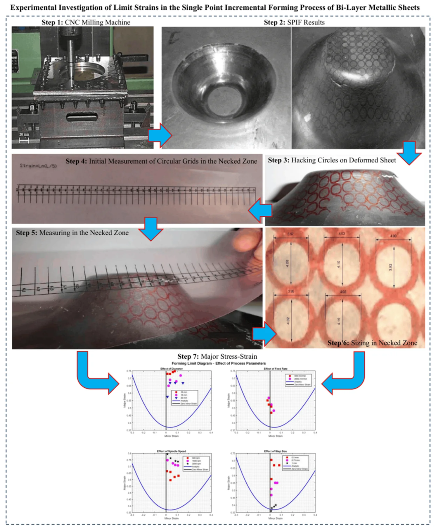
Highlights
- Limit strains of St14-AA3105 bi-layer sheet in SPIF are experimentally characterized
- Step size is dominant: reducing 1 to 0.5 mm raises limit strains by ~65%
- Spindle speed, tool diameter, and feed rate change limit strains by ~28%, ~12%, and ~7%
- SPIF limit strains exceed conventional stamping FLD predicted by the M-K model
- Necking initiates in the outer St14 layer, the formability-limiting constituent
1. Introduction
The automotive, aerospace, and home-improvement industries increasingly require materials that are lightweight while possessing superior mechanical properties. Bi-layer metallic sheets meet this need with a high stiffness-to-weight ratio, improved formability, and enhanced sound and vibration damping, which has expanded their use across these sectors. Leszak patented the incremental forming process (IFP), also known as “die-less forming”, in 1967. The method attracted considerable attention during the 1990s with the development of CNC machines, leading to extensive research in this field [1-3]. In incremental forming, a sheet blank is clamped using a simple fixture while a hemispherical tool gradually deforms the sheet through localized bending and stretching, with the tool path generated by a CNC machine. In single-point incremental forming (SPIF), only one point of the tool is in contact with the sheet blank at any time; two-point incremental forming (TPIF), by contrast, employs an additional supporting tool or backing plate on the opposite side of the sheet. The final thickness of a sheet formed by SPIF can be estimated using the sine law:
where , , and represent the final thickness, initial thickness, and wall angle, respectively; the wall angle therefore plays a critical role in determining the final thickness distribution of the formed component. Incremental forming offers reduced forming-force requirements and eliminates the need for complex dies or molds, making SPIF highly suitable for prototype manufacturing and small-batch production due to its flexibility and low tooling cost. However, the process also has certain limitations, such as relatively low dimensional accuracy and long processing times [4].
Keeler and Backofen introduced the forming limit diagram (FLD) to identify defects such as necking and fracture, investigating the limit strains of brass, copper, steel, and aluminum sheets immediately before failure and thereby establishing the right-hand side (positive minor strain region) of the FLD [5]. Goodwin subsequently extended the FLD to include the left-hand side corresponding to negative minor strains [6]. Forming limit diagrams can be represented in both stress and strain spaces, each governed by different theoretical assumptions. A previous study [7] investigated the effects of anisotropy, strain-hardening coefficient, thickness, and pre-strain on the forming limits of zinc sheets used in the automotive industry; increasing the strain-hardening coefficient was found to improve formability, formability was higher along the rolling direction and decreased with increasing pre-strain, and increasing sheet thickness also enhanced formability. Nair [8] reported that step size, wall angle, feed rate, spindle speed, and tool-sheet friction significantly affect limit strains during the SPIF process, and that smaller step sizes and tool diameters, together with higher spindle speeds, improve the attainable limit strains. Another study [9] investigated the influence of feed rate on the formability of aluminum sheets during incremental forming and showed that reducing the feed rate improves the limit strains. Research reported in [10] examined the formability of aluminum sheets in the SPIF process and found that forming limits are strongly influenced by material type, sheet thickness, tool diameter, and step size. Another investigation [11] studied the incremental forming of sandwich panels and demonstrated that SPIF is suitable for manufacturing AL/PP/AL and MS/PP/MS sandwich structures despite the flexibility and limited compressibility of their cores. An investigation into the formability of AZ31 alloy at elevated temperatures [12] revealed optimal formability above 150 °C. Another study [13] evaluated the hot incremental forming behavior of AA2024-T3, AZ31B-O, and Ti6Al4V alloys, showing that increasing the wall angle decreases surface roughness of the formed wall, while increasing temperature enhances formability. A further study [14] investigated the effects of tool path and process parameters on forming force, finding that increasing step size increases forming force, increasing spindle speed increases the vertical force while reducing the horizontal force, and increasing feed rate increases the vertical forming force. Numerous researchers have proposed advanced techniques to improve the geometric accuracy of incremental forming processes. One investigation [15] introduced a dynamic local-heating technique using laser irradiation, in which a laser spot locally heats the tool-path region, and reported that local heating effectively reduces residual stresses generated during forming. Another study [16] showed that local heating reduces forming force, springback, and geometric inaccuracies while improving formability. Electromagnetic incremental forming (EMIF) has also been applied to aluminum tubes and sheets [17], demonstrating that large components can be formed using relatively small coils and low discharge energies.
Based on the literature, most previous studies have focused on SPIF of monolithic sheets. In contrast, relatively limited research has been conducted on SPIF of metal/metal laminated sheets, despite the superior mechanical properties of layered metallic materials (LMMs) compared with conventional monolithic materials; SPIF provides a cost-effective manufacturing route for such structures. One study investigated the delamination behavior of steel/steel bi-layer sheets during SPIF, produced by roll bonding with thickness reduction ratios of 47 %, 58 %, and 70 %. Substantial improvements in bond strength were observed, with mode I and mode II bond strengths increasing by 572 % and 15.6 %, respectively, as thickness reduction increased, while the critical strain energy release rate (CSERR) increased by 3992 % in mode I but decreased by 20 % in mode II; a surface-based cohesive zone model successfully simulated the delamination behavior, in good agreement with experiments [18]. Another study [19] examined the effect of pre-rolling temperature on the interfacial properties and formability of steel/steel bi-layer sheets formed by SPIF at 700, 800, and 950 °C with a thickness reduction ratio of 58 %; T-peel and tensile shear tests showed that increasing pre-rolling temperature significantly improved bond strength and CSERR, and that formability, represented by the maximum wall angle, improved accordingly, indicating a strong relationship between interfacial properties and formability. For the first time, another study applied SPIF to aluminum/magnesium bi-layer sheets consisting of Al1050 and AZ31B alloys [20]; finite element simulations in ABAQUS evaluated five failure criteria, with the FLD criterion providing the most accurate predictions and good agreement between experimental and numerical thickness distributions, while the Mg-AZ31B/Al1050 arrangement achieved higher fracture strains than the reverse configuration, smaller tool diameters improved formability, and increasing step-down reduced it. Another investigation [21] studied the single-stage incremental hole-flanging (IHF) process of adhesively bonded Al1050/DC01 bi-layer sheets through experiments and finite element analysis, finding that larger initial hole diameters and greater vertical tool steps increased minimum flange wall thickness, larger tool tip radii increased tensile strains and wall thinning, and flange wall angle and initial hole diameter significantly influenced interfacial separation during early forming. Another study [22] employed FormingSuite software to simulate the SPIF process of galvanized circular sheets, confirming the feasibility and effectiveness of the proposed method through experimental and simulation agreement. The SPIF of bi-layer and multilayer sheets has demonstrated that forming limits differ significantly from those of monolithic sheets and conventional forming processes, and are strongly influenced by layer arrangement, bonding method, and process parameters. For explosively welded CP-Ti/St12 bimetals, FLDs obtained from SPIF showed that the Ti/St configuration improved formability by approximately 30 % compared with the St/Ti arrangement, with finite element predictions of rupture depth and thickness distribution agreeing well with experiments [23-26]. In roll-bonded Al1050/brass bi-layer sheets, the FLD was successfully predicted using the second derivative of equivalent plastic strain, with numerical predictions differing from experimental results by only about 7 % at a wall angle of 62.5° [24]. Layer arrangement was consistently identified as a key design parameter: positioning titanium on the tool side improved formability in CP-Ti/St12 sheets, while brass/aluminum configurations exhibited better formability than aluminum/brass configurations [23], [24]. A comprehensive numerical and experimental investigation of roll-bonded Cu/Al composites showed that the layer-up configuration primarily experienced compressive deformation, whereas the layer-down configuration was dominated by stretching deformation; consequently, Al/Cu sheets exhibited higher formability and larger forming forces than Cu/Al sheets [25]. Similarly, experiments on brass/St13 bi-layer sheets demonstrated that placing steel on the outer surface increased fracture height and maximum strain [26]. Process parameters such as step-down, tool diameter, spindle speed, and feed rate also significantly affect forming limits: increasing tool diameter, vertical step size, and feed rate generally reduces fracture height, fracture angle, and maximum strain [3], and thickness distribution and local strain evolution are also strongly affected by layer arrangement and process parameters [23], [24]. For steel/polymer/steel sandwich composites, SPIF experiments showed that although the limiting wall angle and fracture forming limit curves resembled those of monolithic sheets, failure occurred earlier and involved cracking, delamination, and galling; nevertheless, sine-law predictions and fracture forming limit curves (FFLCs) remained effective for characterizing formability, and multi-stage SPIF extended the achievable forming window [27].
Comparisons between SPIF and conventional forming consistently demonstrate that SPIF provides significantly higher fracture strains due to its highly localized and non-proportional deformation path. For explosively welded Al/Cu laminated sheets, finite element simulations employing coupled damage-plasticity models and the Xue-Wierzbicki damage criterion showed that FFLCs obtained from SPIF were substantially higher than those derived from hemispherical punch stretching tests, with the complex stress and strain states also mapped in stress triaxiality-Lode angle and FLD spaces [28]. Studies on monolithic materials such as AISI 304, AA1050, AA5083, and DP590 steel similarly reported significantly higher fracture strains in SPIF compared with Nakazima and stretch-bending tests [29-33]. These findings have led researchers to conclude that damage-based criteria and FFLCs are more suitable than conventional FLDs for evaluating formability in SPIF processes, including bi-layer and sandwich structures [23], [24], [25], [28], [34]. Overall, the SPIF behavior of bi-layer and sandwich sheets is governed by a complex interaction among layer arrangement, process parameters, and interfacial properties; with appropriate optimization of these factors and the use of advanced damage- or strain-based criteria, both experimental and finite element approaches can accurately predict fracture behavior and guide process optimization.
Beyond empirical characterization of SPIF formability, analytical frameworks have also been proposed to explain the underlying mechanics. The Marciniak-Kuczyński (M-K) model, originally developed for conventional stamping, predicts the onset of localized necking from an assumed geometric or material imperfection. A complementary membrane-based approach, incorporating bi-directional in-plane contact friction at the tool-sheet interface, has also been used to explain the enhanced formability of SPIF relative to conventional stamping [35]. More recently, data-driven approaches have also been applied to predict SPIF failure directly from experimental process and thickness data: a multi-objective neural-network framework optimized with a non-dominated sorting genetic algorithm (NSGA-II) has been used to classify crack versus non-crack outcomes in galvanized steel sheets as a function of spindle speed, feed rate, and tool-path parameters, demonstrating strong generalization performance across independent cross-validation folds [36].
In the present study, the limit strains of St14-AA3105 laminated sheets during the SPIF process are experimentally investigated. In addition, the theoretical FLD for conventional stamping of St14-AA3105 sheets is predicted using the M–K model, and the resulting limit strains are compared with those obtained from SPIF experiments. The main contributions of this study are as follows:
Systematic experimental investigation of the effects of SPIF parameters on the limit strains of St14-AA3105 laminated sheets.
Direct comparison between SPIF experimental results and M-K-model predictions for conventional stamping.
Practical recommendations for selecting SPIF process parameters to maximize the formability of the studied laminated sheet.
The experimental procedures and M-K modeling approach are presented in Section 2, followed by the results and discussion in Section 3 and the conclusions in Section 4.
2. Methodology
2.1. Analytical approach
Analytical approaches to necking analysis in sheet metal forming fall into three main families: geometric-imperfection (macro-defect) models, bifurcation theory, and continuum damage mechanics. Among these, the M-K model, originally proposed by Marciniak and Kuczyński [37], is the most widely used geometric-imperfection approach and is adopted in the present study to predict the forming limit diagram (FLD) of the St14-AA3105 laminated sheet under conventional stamping conditions; the membrane-based analysis discussed in Section 1 [35] instead provides insight into the local stress state at the tool-sheet contact interface during SPIF itself, and is not used for the FLD prediction here. In the M-K model, a region containing a small geometric defect, or groove, is assumed to exist on the sheet surface, and localized necking initiates within this defected region once the imposed straining reaches a critical level. The severity of the defect is quantified by the imperfection factor, , defined as the ratio of the current thickness in the defected region, , to the current thickness in the surrounding, defect-free (safe) region, (Fig. 1). Its initial value, , corresponds to this same ratio evaluated at the onset of deformation, before any straining has occurred, and is expressed by Eq. (2), following the two-layer M-K formulation of Aghchai et al. [38]:
where the superscripts a and b denote the safe and defected regions, respectively, the subscript (= 1, 2) indexes the two metallic layers of the laminated sheet, and is the through-thickness (thinning) strain. The limit strains are obtained by solving the equilibrium equation across the groove. Force equilibrium perpendicular to the groove, summed over the two layers of the laminated sheet, is expressed by Eq. (3):
where is the major principal stress, is the effective (equivalent) stress, and t is the thickness, each evaluated in the safe (a) or defected (b) region of layer i. Straining continues in the safe region as long as this equilibrium is satisfied; once the strain increment required to maintain equilibrium in the defected region exceeds that in the safe region by a critical amount, deformation localizes within the groove and the corresponding strain state defines the forming limit. By applying Hill's non-quadratic yield criterion together with Swift’s plastic constitutive relation, the force-equilibrium condition of Eq. (3) can be rewritten in terms of the layers' hardening behavior, giving Eq. (4):
where and are the strength coefficient and strain-hardening exponent of layer in Swift’s law, is the initial thickness, and are the effective strain and its increment, and is the ratio of the major principal stress to the effective stress for each region, defined next in Eq. (5):
The proportionality of the loading path is enforced through strain compatibility across the groove: since the safe and defected regions remain rigidly connected along the groove direction, the strain increment along the groove must be identical on both sides, . Writing each region's major-strain increment in terms of its own strain ratio gives the compatibility condition of Eq. (7):
where:
where is the normal anisotropy coefficient (Table 1) and is the Hill non-quadratic yield exponent of layer , and , is the stress-ratio parameter defined next in Eq. (9). Since and depend on one another through Eqs. (5), (8), and (9), the two are solved together by iteration at each strain increment until convergence is reached. Following the crystal-structure-based convention of Logan and Hosford [39], the exponent was taken as 6 for the body-centered-cubic St14 layer and 8 for the face-centered-cubic AA3105 layer. Thus, the , is calculated by Eq. (9):
where the auxiliary function is given by Eq. (10):
The system of Eqs. (3-10) is solved incrementally: at each imposed increment in the safe region, is adjusted until Eq. (4) is satisfied, so that force equilibrium across the groove is maintained at every step. Straining proceeds increment by increment until the strain-increment ratio diverges, signaling the onset of localized necking in the groove; the corresponding pair defines one point on the forming limit diagram.
Fig. 1Schematic of the bi-layer laminated sheet showing the safe region (a) and the defected (grooved) region (b) used in the M-K model, with the subscripts i= 1, 2 denoting the two constituent metal layers
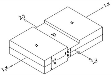
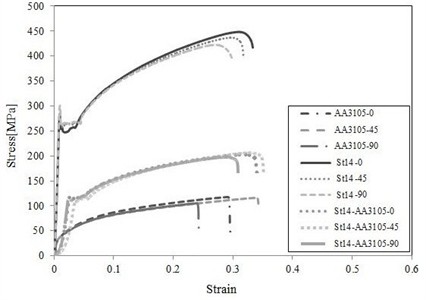
Fig. 2True stress-strain curves of AA3105, St14, and the laminated sheet in the 0°, 45°, and 90° directions relative to rolling
2.2. Material characterization
To obtain the material parameters required by the M-K model (, , and in Eqs. (4) and (8)), uniaxial tensile tests were performed on AA3105, St14, and the laminated sheet in three directions relative to the rolling direction (0°, 45°, 90°). The resulting true stress-strain curves are presented in Fig. 2. The strain-hardening exponent n and strength coefficient were extracted from Swift's law fit to each curve, and the normal anisotropy coefficient was calculated as the weighted average of the three directional values, . The strain-rate sensitivity exponent m, which cannot be obtained from a single quasi-static tensile curve, was taken from the literature for the corresponding alloys and is reported in Table 1 for completeness; it does not enter the rate-independent M-K formulation used here. The resulting mechanical properties of AA3105, St14, and the laminated sheet are summarized in Table 1.
Table 1Mechanical properties of AA3105, St14, and the St14-AA3105 laminated sheet, extracted from the uniaxial tensile tests of Fig. 2 (Swift’s law fit; R is the weighted-average normal anisotropy coefficient from the 0°, 45°, and 90° directions, R=r0+2r45+r904
Material | (MPa) | |||
St14 | 0.31 | 0.0155 | 670 | 1.07 |
AA3105 | 0.29 | 0 | 169 | 0.4915 |
St14-AA3105 | 0.33 | 0.01 | 320 | 1.05 |
Where , strain-hardening exponent, , strain-rate sensitivity exponent, , strength coefficient in Swift's law , and is normal anisotropy coefficient | ||||
2.3. Experimental procedure
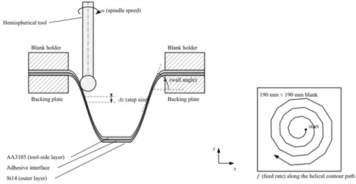
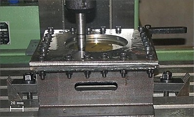
This section describes the experimental procedure used to obtain the limit strains of the St14-AA3105 laminated sheet in the SPIF process. The SPIF process is shown schematically in Fig. 3(a). The bi-layer blank is clamped at its perimeter between a blank holder and a backing plate, and a hemispherical tool, rotating at the spindle speed and travelling along a helical contour path, deforms the sheet locally by bending and stretching, descending by one vertical step per contour pass. As shown in Fig. 3(b), the experiments were carried out on a three-axis CNC milling machine.
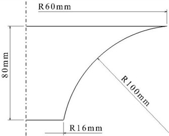
The intended shape and dimensions of the formed part are shown in Fig. 4. Based on Eq. (1), as the forming depth increases, the sheet thickness decreases progressively, and necking eventually occurs [2]. A hemispherical tool, machined from AISI 4140 steel and quenched in oil to achieve the required hardness, was used to form the hyperbolic parts. SAE40 lubricant was applied to reduce friction between the tool and the sheet during the SPIF process.
Table 2SPIF process parameters and levels
Parameter | Low | Medium | High |
Step size (mm) | 0.5 | 0.75 | 1 |
Feed rate (mm/min) | 500 | 1250 | 2000 |
Tool diameter (mm) | 10 | 15 | 20 |
Spindle speed (rpm) | 300 | 1650 | 3000 |
The St14-AA3105 laminated sheet, with a total thickness of 1.1 mm, consists of two 190 mm × 190 mm × 0.5 mm layers of St14 and AA3105 bonded together with an approximately 0.1 mm layer of two-component polyurethane adhesive under a cold press. To improve bonding between the metal layers and the adhesive, the metal surfaces were surface-treated according to ASTM D2651. The mechanical properties of AA3105 and St14 were determined from uniaxial tensile tests on specimens prepared according to ASTM E8M in three directions (0°, 45°, and 90°) relative to the rolling direction (Section 2.2, Fig. 2, Table 1). The SPIF process was then carried out on the St14-AA3105 laminated sheet at the parameter levels listed in Table 2 to obtain the principal limit strains; to isolate the effect of a given factor, that factor was varied across its three levels while the remaining factors were held at their medium level.
Fig. 3Single point incremental forming of the St14-AA3105 laminated sheet: a) schematic of the process, showing the clamped bi-layer blank with the AA3105 layer facing the tool, the hemispherical tool, the vertical step size ∆z, the wall angle α, and the helical contour tool path; b) experimental setup on the three-axis CNC milling machine
a)
b)
Fig. 4Geometry of the formed part
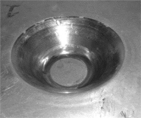
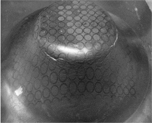
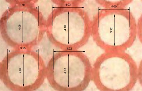
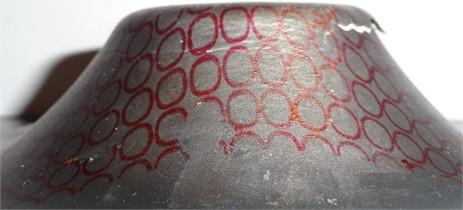
During the SPIF process, the AA3105 side of the laminated sheet was in contact with the hemispherical tool; since steel exhibits higher springback than aluminum, the steel layer was placed beneath the aluminum layer, as the reverse arrangement caused the layers to separate. Fig. 5 shows the formed part and the circular grid pattern on its wall. Circular grids with a diameter of 4 mm were stamped on the laminated sheet to measure the limit strains in the necked zone, with each circle numbered to allow it to be tracked after forming. The initial and final diameters of the circles were measured using AutoCAD 2010 software, as shown in Fig. 6(a). Because the formed part had a curvilinear wall, the deformation of the circular grids was measured using a flexible, transparent, calibrated measuring strip, as shown in Fig. 6(b). Fig. 7 shows the formed hyperbolic geometry (a) and the laminated sheet after forming (b). Digital image correlation was not used for this geometry. The hyperbolic part is 80 mm deep with a wall that curves continuously from a shallow angle at the rim to a steep angle near the base, so a stereo-DIC pair mounted above the fixture loses line of sight to the lower wall, where necking occurs, and the strongly oblique viewing angle on the remaining visible region degrades correlation accuracy in exactly the zone of interest. In addition, the sprayed speckle pattern is progressively damaged by the sliding contact of the lubricated tool over the tool-side surface across the many passes required, whereas the stamped circular grid survives on the opposite (St14) surface, which is not in contact with the tool. The calibrated flexible strip conforms to the curvilinear wall and therefore measures the true arc length of the deformed grid rather than its projection, giving a direct measurement of the principal strains in the necked zone.
Fig. 5a) Laminated sheet formed by SPIF on the CNC milling machine; b) circular grid pattern on the formed sheet, used to measure the strains in the necked zone
a)
b)
Fig. 6a) Undeformed circular grid measured in AutoCAD 2010, showing the reference diameters (nominally 4 mm) used as L₀ in the strain calculation; b) the calibrated flexible strip used to measure grid dimensions along the curvilinear wall. Principal strains were evaluated as ε=lnLL0 with L0= 4, the printed grid diameter, and L the corresponding major or minor axis of the deformed ellipse
a)

b)
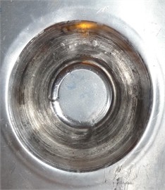
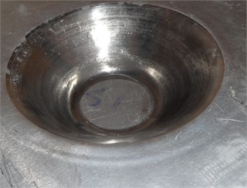
Fig. 8 shows the deformed grid pattern across the curved wall in the necked zone. As the tool descends along the hyperbolic profile of Fig. 4, tracing a circular contour pass at each depth, the local wall angle increases continuously toward the top of the part, and the sheet thickness decreases correspondingly, per Eq. (1). This continuously varying geometry allows the depth at which rupture occurs to be identified directly with a specific wall angle-thickness combination, which is plotted as one point on the FLD (Fig. 9). A constant-angle profile, such as a truncated cone, would not offer this resolution: it indicates only whether that single angle exceeds the forming limit, without locating a rupture depth along a continuum of angles. One SPIF experiment was performed at each parameter setting. From each formed part, five to six circular grids in the immediate vicinity of the fracture zone were measured, and each of these measurements is plotted as a separate point in Fig. 9; the scatter within each parameter level therefore reflects the spatial variation of strain around the necked region rather than run-to-run variation.
Fig. 7a) Geometry of the formed hyperbolic part, b) laminated sheet after performing the SPIF process
a)
b)
Fig. 8Deformed circular grid pattern in the necked zone of the formed hyperbolic part, shown across the curved wall
3. Results and discussion
3.1. Effect of process parameters on limit strains
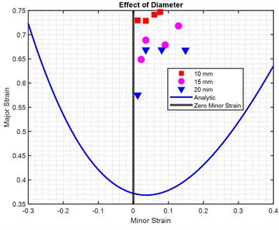
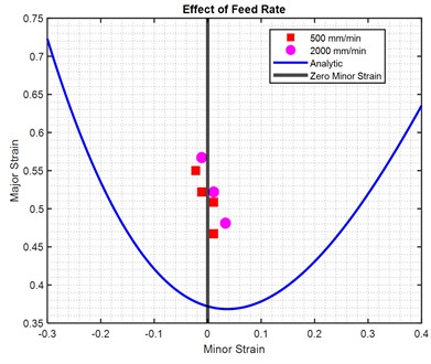
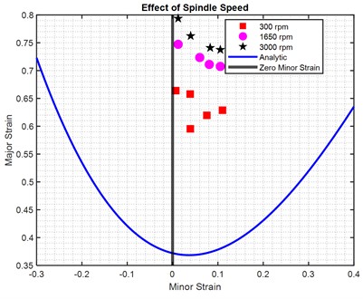
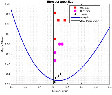
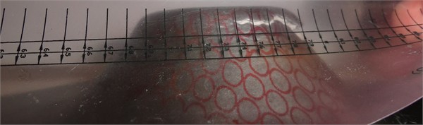
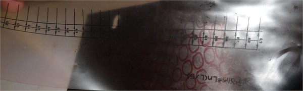
Fig. 9 presents the forming limit diagram (FLD) of the studied laminated sheet under conventional stamping conditions, obtained using the M-K model and shown as the solid curve in all four panels, together with the experimentally measured SPIF limit strains; panel (d) shows the effect of step size on the limit strains of the laminated sheet in the SPIF process.in the SPIF process. The results show that the limit strains in the SPIF process are sensitive to step size, with an inverse relationship between the two: limit strains increase by approximately 65 % as the step size decreases from 1 mm to 0.5 mm. This trend is attributed to increasing step size raising stress concentration and dislocation accumulation at the tool-sheet contact area [19]. It should also be noted that, at all step-size levels tested, necking consistently initiates in the outer layer (St14); Fig. 10 shows the calibrated strip applied to a cracked and an uncracked formed specimen. Moreover, the SPIF strain points in Fig. 9 lie consistently above the theoretical stamping FLD, confirming that the SPIF process increases the attainable limit strains of the laminated sheet relative to conventional stamping. One of the most important parameters affecting limit strains is the ratio, where is the hydrostatic stress and is the yield stress [26]. This ratio for conventional stamping and for the SPIF process can be calculated using Eqs. (11) and (12), respectively [24]:
where is the punch radius, is the forming-tool radius, and t is the sheet thickness. Since , the ratio is correspondingly higher in conventional stamping processes than in the SPIF process, leading to a higher rate of accumulated damage growth [26]. Consequently, the limit strains attained in the SPIF process are higher than those in conventional stamping.
Fig. 9Forming limit diagram (FLD) of the laminated sheet under conventional stamping (M-K model prediction) with the experimentally measured SPIF limit strains overlaid, showing the effects of a) tool diameter, b) feed rate, c) spindle speed, and d) step size
a)
b)
c)
d)
The effect of tool diameter on the limit strains of the studied laminated sheet is shown in Fig. 9(a). Decreasing the tool diameter from 20 mm to 10 mm increases the limit strains by approximately 12 % in the SPIF process. According to Eq. (12), the ratio increases monotonically with the tool radius, leading to a higher rate of accumulated damage growth; increasing the tool diameter therefore increases the ratio and consequently decreases the limit strains. Fig. 9(b) also shows the effect of feed rate on the limit strains of the laminated sheet in the SPIF process: increasing the feed rate from 500 mm/min to 2000 mm/min slightly reduces the limit strains of the sheet, by approximately 7 %. Only these two levels were formed in the feed-rate study; the intermediate level of 1250 mm/min listed in Table 2 served as the fixed baseline feed rate while the other three parameters were varied. The effect of spindle speed on the limit strains of the laminated sheet in the SPIF process is shown in Fig. 9(c). Increasing spindle speed from 300 rpm to 1650 rpm produces a substantial increase in limit strains, but the rate of increase then diminishes at higher spindle speeds, so that the overall increase from 300 rpm to 3000 rpm is approximately 28 %.
Fig. 10Strain measurement using the calibrated measuring strip applied to formed test samples
4. Conclusions
In this study, the limit strains of the St14-AA3105 laminated sheet in the SPIF process were experimentally investigated across a range of process parameters, and a forming limit diagram (FLD) for the laminated sheet under conventional stamping conditions was predicted using the M-K model. The main findings are summarized as follows:
1) The limit strains attained in the SPIF process are consistently higher than those in conventional stamping. Consequently, FLDs obtained for conventional stamping are not directly applicable for predicting limit strains in the SPIF process, and a dedicated SPIF-specific characterization, as performed here, is required.
2) Among the process parameters investigated, step size has the strongest effect on formability: reducing the step size from 1 mm to 0.5 mm increases the limit strains by approximately 65 %.
3) Spindle speed has the second-strongest effect: increasing the spindle speed from 300 rpm to 3000 rpm increases the limit strains by approximately 28 %, with most of the gain occurring at lower speeds before the rate of improvement diminishes.
4) Decreasing the tool diameter from 20 mm to 10 mm increases the limit strains by approximately 12 %.
5) Increasing the feed rate from 500 mm/min to 2000 mm/min reduces the limit strains by approximately 7 %, the smallest effect among the four parameters studied.
6) In all tested conditions, necking consistently initiated in the outer (St14) layer of the laminated sheet, indicating that the outer layer is the formability-limiting constituent of the St14-AA3105 laminate.
References
-
W. C. Emmens, G. Sebastiani, and A. H. van den Boogaard, “The technology of incremental sheet forming-a brief review of the history,” Journal of Materials Processing Technology, Vol. 210, No. 8, pp. 981–997, Feb. 2010, https://doi.org/10.1016/j.jmatprotec.2010.02.014
-
M. Hasanlu and S. Mokari, “Practical survey in single – and two-points incremental metal forming,” Muhandis-i mikānīk, 2025, https://doi.org/10.13140/rg.2.2.15978.22723
-
M. Hasanlu and S. Mokary, “Review of the parameters influence of incremental forming between 1960 and 2019,” Journal of Mechanical Engineering and Vibration, Vol. 10, No. 1, pp. 32–45, 2019.
-
J. Jeswiet, F. Micari, G. Hirt, A. Bramley, J. Duflou, and J. Allwood, “Asymmetric single point incremental forming of sheet metal,” CIRP Annals, Vol. 54, No. 2, pp. 88–114, Jun. 2008, https://doi.org/10.1016/s0007-8506(07)60021-3
-
S. P. Keeler, Plastic instability and fracture in sheets stretched over rigid punches. 1961.
-
G. M. Goodwin, “Application of strain analysis to sheet metal forming problems in the press shop,” in SAE Technical Paper Series, Vol. 1, 1968, https://doi.org/10.4271/680093
-
Rees and D. W. A., “Factors influencing the FLD of automotive sheet metal,” Journal of Materials Processing Technology, Vol. 118, No. 1-3, pp. 1–8, Oct. 2002, https://doi.org/10.1016/s0924-0136(01)01030-5
-
M. Nair, “An experimental and numerical investigation of the steady state forces in single incremental sheet forming,” 2012.
-
M. Strano, “Technological representation of forming limits for negative incremental forming of thin aluminum sheets,” Journal of Manufacturing Processes, Vol. 7, No. 2, pp. 122–129, Sep. 2008, https://doi.org/10.1016/s1526-6125(05)70089-x
-
M. Ham and J. Jeswiet, “Forming limit curves in single point incremental forming,” CIRP Annals, Vol. 56, No. 1, pp. 277–280, Jun. 2007, https://doi.org/10.1016/j.cirp.2007.05.064
-
K. P. Jackson, J. M. Allwood, and M. Landert, “Incremental forming of sandwich panels,” in Journal of Materials Processing Technology, Vol. 204, Stafa: Trans Tech Publications Ltd., 2008, pp. 290–303, https://doi.org/10.4028/0-87849-437-5.591
-
Y. H. Ji and J. J. Park, “Incremental forming of free surface with magnesium alloy AZ31 sheet at warm temperatures,” Transactions of Nonferrous Metals Society of China, Vol. 18, pp. s165–s169, Jun. 2010, https://doi.org/10.1016/s1003-6326(10)60195-1
-
G. Ambrogio, L. Filice, and F. Gagliardi, “Formability of lightweight alloys by hot incremental sheet forming,” Materials and Design, Vol. 34, pp. 501–508, 2012, https://doi.org/10.1016/j.matdes.2011.08.024
-
H. Ghasemi and B. Soltani, “Experimental investigation on the effective parameters on forming force, dimensional accuracy and thickness distribution in single point incremental forming,” 2015.
-
R. Hino, K. Kawabata, and F. Yoshida, “Incremental forming with local heating by laser irradiation for magnesium alloy sheet,” Procedia Engineering, Vol. 81, pp. 2330–2335, Oct. 2014, https://doi.org/10.1016/j.proeng.2014.10.329
-
J. R. Duflou, B. Callebaut, J. Verbert, and H. de Baerdemaeker, “Improved SPIF performance through dynamic local heating,” International Journal of Machine Tools and Manufacture, Vol. 48, No. 5, pp. 543–549, Aug. 2007, https://doi.org/10.1016/j.ijmachtools.2007.08.010
-
X. H. Cui et al., “Electromagnetic incremental forming (EMIF): a novel aluminum alloy sheet and tube forming technology,” Journal of Materials Processing Technology, Vol. 214, No. 2, pp. 409–427, Jul. 2013, https://doi.org/10.1016/j.jmatprotec.2013.05.024
-
M. Hassan, G. Hussain, M. Ilyas, and A. Ali, “Delamination analysis in single-point incremental forming of steel/steel bi-layer sheet metal,” Archives of Civil and Mechanical Engineering, Vol. 20, No. 2, p. 39, Mar. 2020, https://doi.org/10.1007/s43452-020-00025-1
-
M. Hassan et al., “Effect of pre-rolling temperature on the interfacial properties and formability of steel-steel bilayer sheet in Single Point Incremental Forming,” Proceedings of the Institution of Mechanical Engineers, Part B: Journal of Engineering Manufacture, Vol. 235, No. 3, pp. 406–416, Oct. 2020, https://doi.org/10.1177/0954405420963004
-
P. Tayebi and R. Hashemi, “Study of single point incremental forming limits of Al 1050/Mg-AZ31B two-layer sheets fabricated by roll bonding technique: finite element simulation and experiment,” Journal of Materials Research and Technology, Vol. 29, pp. 149–169, Jan. 2024, https://doi.org/10.1016/j.jmrt.2024.01.085
-
M. Emami, M. Morovvati, B. Mollaei-Dariani, and A. F. Arezoodar, “Investigation of the formability of Al1050/DC01 bi-layer sheet in incremental hole-flanging: experimental and numerical simulation,” European Journal of Mechanics-A/Solids, Vol. 111, p. 105579, 2025, https://doi.org/10.2139/ssrn.4985389
-
M. Hasanlu and S. Mokari, “Numerical-experimental single point incremental forming of thin circular plate,” Advanced Manufacturing Research, Vol. 3, No. 1, pp. 1–13, Jun. 2025, https://doi.org/10.21595/amr.2025.24756
-
H. Rezaei and M. Honarpisheh, “Experimental and numerical investigation of forming limit diagram of CP-Ti/St12 bimetal in the incremental forming process,” Strength of Materials, Vol. 54, No. 4, pp. 681–694, Nov. 2022, https://doi.org/10.1007/s11223-022-00446-8
-
A. Jalali, R. Hashemi, M. Rajabi, and P. Tayebi, “Finite element simulations and experimental verifications for forming limit curve determination of two-layer aluminum/brass sheets considering the incremental forming process,” Proceedings of the Institution of Mechanical Engineers, Part L: Journal of Materials: Design and Applications, Vol. 236, No. 2, pp. 361–373, Oct. 2021, https://doi.org/10.1177/14644207211045212
-
Z. Liu and G. Li, “Single point incremental forming of Cu-Al composite sheets: a comprehensive study on deformation behaviors,” Archives of Civil and Mechanical Engineering, Vol. 19, No. 2, pp. 484–502, Jan. 2019, https://doi.org/10.1016/j.acme.2018.11.011
-
R. Ashouri and H. Shahrajabian, “Experimental investigation of incremental forming process of bilayer hybrid brass/St13 sheets,” 2017.
-
M. Harhash and H. Palkowski, “Incremental sheet forming of steel/polymer/steel sandwich composites,” Journal of Materials Research and Technology, Vol. 13, pp. 417–430, May 2021, https://doi.org/10.1016/j.jmrt.2021.04.088
-
A. Z. Dizajyekan, M. J. Mirnia, and B. M. Dariani, “Fracture investigation in single point incremental forming of the Al/Cu laminated sheets using coupled damage plasticity model,” CIRP Journal of Manufacturing Science and Technology, Vol. 43, pp. 242–259, 2023, https://doi.org/10.1016/j.cirpj.2023.04.010
-
G. Centeno, I. Bagudanch, A. J. Martínez-Donaire, M. L. García-Romeu, and C. Vallellano, “Critical analysis of necking and fracture limit strains and forming forces in single-point incremental forming,” Materials and Design, Vol. 63, pp. 20–29, Nov. 2014, https://doi.org/10.1016/j.matdes.2014.05.066
-
G.-P. Rusu, V. Oleksik, R. E. Breaz, D. Dobrotă, and I. O. Popp, “Analysis of the metal sheets formability at single point incremental forming process,” MATEC Web of Conferences, Vol. 368, p. 01006, Oct. 2022, https://doi.org/10.1051/matecconf/202236801006
-
G. Kumar and K. Maji, “Investigations into enhanced formability of AA5083 aluminum alloy sheet in single-point incremental forming,” Journal of Materials Engineering and Performance, Vol. 30, No. 2, pp. 1289–1305, Jan. 2021, https://doi.org/10.1007/s11665-021-05455-3
-
S. Pandre, A. Morchhale, N. Kotkunde, and S. Kurra, “Processing of DP590 steel using single point incremental forming for automotive applications,” Materials and Manufacturing Processes, Vol. 36, No. 14, pp. 1658–1666, Oct. 2021, https://doi.org/10.1080/10426914.2021.1942903
-
S. Pandre, A. Morchhale, G. Mahalle, N. Kotkunde, K. Suresh, and S. K. Singh, “Fracture limit analysis of DP590 steel using single point incremental forming: experimental approach, theoretical modeling and microstructural evolution,” Archives of Civil and Mechanical Engineering, Vol. 21, No. 3, p. 95, May 2021, https://doi.org/10.1007/s43452-021-00243-1
-
A. Gohil and B. Modi, “Experimental determination of fracture forming line for AA1100 aluminum sheet in single point incremental forming process,” Materials Today: Proceedings, Jun. 2023, https://doi.org/10.1016/j.matpr.2023.05.733
-
P. A. F. Martins, N. Bay, M. Skjoedt, and M. B. Silva, “Theory of single point incremental forming,” CIRP Annals, Vol. 57, No. 1, pp. 247–252, May 2008, https://doi.org/10.1016/j.cirp.2008.03.047
-
M. Hasanlu, “Optimal binary thickness recognition for experimental comparative failure analysis in single point incremental forming,” Advanced Manufacturing Research, Vol. 4, No. 1, pp. 1–20, Jun. 2026, https://doi.org/10.21595/amr.2026.26574
-
Z. Marciniak and K. Kuczyński, “Limit strains in the processes of stretch-forming sheet metal,” International Journal of Mechanical Sciences, Vol. 9, No. 9, pp. 609–620, Mar. 2003, https://doi.org/10.1016/0020-7403(67)90066-5
-
A. J. Aghchai, M. Shakeri, and B. Mollaei-Dariani, “Theoretical and experimental formability study of two-layer metallic sheet (Al1100/St12),” Proceedings of the Institution of Mechanical Engineers, Part B: Journal of Engineering Manufacture, Vol. 222, No. 9, pp. 1131–1138, Sep. 2008, https://doi.org/10.1243/09544054jem1140
-
R. W. Logan and W. F. Hosford, “Upper-bound anisotropic yield locus calculations assuming “111”-pencil glide,” International Journal of Mechanical Sciences, Vol. 22, No. 7, pp. 419–430, Mar. 2003, https://doi.org/10.1016/0020-7403(80)90011-9
About this article

The authors have not disclosed any funding.
The authors thank their home institution for giving them access to the research facilities and computer resources they used in this study.
The datasets generated during and/or analyzed during the current study are available from the corresponding author on reasonable request.
The authors declare that they have no conflict of interest.

