Abstract
Single Point Incremental Forming (SPIF) represents a transformative shift in sheet metal manufacturing, offering unparalleled flexibility, reduced tooling costs, and adaptability for low-volume and customized production. This study presents a hybrid numerical-experimental investigation of SPIF applied to thin circular galvanized plates, integrating finite element simulations via FormingSuite software with experimental validation. A key innovation of this work lies in its detailed analysis of coupled deformation modes, tensile-tensile and tensile-compressive, governing failure and thinning mechanisms under high forming angles, particularly around 90°, which are typically fracture-prone. The research introduces a novel use of the Fracture Forming Line (FFL) over traditional Forming Limit Curves (FLCs) to better predict failure in SPIF. Results reveal improved strain capacity and process stability, supported by deformation mapping, safe zone identification, and stress-strain simulations. This comprehensive approach not only enhances the predictive capabilities of SPIF modeling but also supports smarter and more sustainable manufacturing processes.
Highlights
- Adoption of Fracture Forming Line (FFL) for Enhanced Failure Prediction
- Hybrid Numerical-Experimental Methodology
- Mapping Safe Zones and Stress Distribution
- Thickness Strain Behavior at High Angles
- Decoupling of Strain and Stress Distributions
1. Introduction
In situations where low-volume production or rapid prototyping is required, traditional sheet metal forming methods often become inefficient due to the necessity of mold fabrication for shaping shell- and sheet-type components. These conventional processes are neither cost-effective nor time-efficient for small-batch manufacturing. As a result, there is a growing demand for flexible, rapid, and economically viable forming techniques. Single Point Incremental Forming (SPIF) has emerged over recent decades as a promising alternative for the production of shell-like geometries. This method is particularly valued for its flexibility and adaptability. Unlike traditional forming methods, SPIF eliminates the need for expensive pressing and mold-making equipment. It utilizes a simple hemispherical-ended tool mounted on a CNC machine, which incrementally deforms the sheet metal along a pre-programmed toolpath. The sheet is fixed in place using a basic clamping system, and the tool applies localized plastic deformation through low-force contact, allowing the shape to develop gradually. One drawback of the SPIF process is its relatively long forming time, caused by the slow, stepwise vertical movement of the tool. However, this trade-off is generally acceptable considering the significant savings in tooling costs and the enhanced process flexibility. Numerous studies have investigated key parameters affecting SPIF. These include material type, forming angle, and tool rotation speed, all of which significantly influence the forming force, as shown in studies on truncated pyramids formed using spherical tools [1]. Advanced methods such as finite element analysis (FEA), electron backscatter diffraction (EBSD), and X-ray diffraction have been employed to study deformation behavior and enhance formability [2]. The use of graphite-based lubricants has been shown to improve formability and surface finish in Ti-6Al-4V sheets [3]. The arrangement of material layers also influences formability, with forming force identified as a critical factor [4]. Response surface methodology and regression modeling have been used to optimize lab-scale incremental forming setups for AA6061 sheet metal [5]. Investigations into SPIF for flat-bottomed parts, including aerospace components, highlight its suitability for both prototyping and production [6]. Other studies explored deformation behavior in stainless steels with ferritic microstructures, focusing on tool diameter and vertical step size effects on lattice rotation [7]. High-angle and flat-end tools were observed to cause fracture in AA2024-O sheets [8]. SPIF is widely accepted for producing prototypes and custom components using CNC machines, simplifying design iteration and small-batch manufacturing [9][10]. Parameters such as step size, tool diameter, and spindle speed directly affect axial peak forces in AA2024-O sheets [11]. Experimental and numerical analysis on aluminum 8011 alloy showed successful formability using Taguchi and ANOVA methods [12]. Friction stir-assisted SPIF has also been shown to improve both surface quality and formability [13]. Process optimization techniques have been applied to IS513 Cr3 sheets using variance analysis and response surface methodology [14]. Studies on complex geometries have identified step-down increment and shearing-induced hardening as key factors in residual stress formation [15]. Research on AA3003-H18 aluminum alloy sheets demonstrated the influence of step size and feed rate on formability and fracture risk using statistical modeling [16]. A comparative analysis using an analytical membrane model indicated that tube-by-tube SPIF increases fracture resistance, suggesting different deformation and damage accumulation mechanics [17]. Sheet anisotropy also affects stress triaxiality and effective fracture strains, impacting fracture behavior in frustum shapes [18]. The simulation of SPIF for AA7075 aluminum sheets using the Yld2004-18P yield function, calibrated with crystal plasticity finite element methods, accurately predicted material behavior and matched experimental results, validating the simulation approach [19]. Further research has developed new SPIF forming limit evaluation techniques and analyzed forming limits under various conditions [20]. SPIF has also been extended to polymer materials, with studies addressing deformation mechanics, failure modes, and industrial relevance [21]. Process variables such as tool diameter, coolant type, and feed rates affect the surface hardness of AA1100 aluminum sheets [22]. Reviews of ISF developments from 2015-2021 highlight new technologies and application insights [23]. Research has also shown that damage accumulation during SPIF governs the cyclic loading behavior during tube expansion [24]. A numerical-experimental study using DC04 steel evaluated strain, thinning, pressure, and processing time, revealing the influence of tool diameter and forming angle [25]. Multi-stage SPIF (MSPIF) comparisons showed DC04 steel exhibits higher forming forces and thinner regions than AA1050 [26]. Central composite design (CCD) and ANOVA were used to optimize parameters influencing surface roughness and forming time [27]. Residual stress in SPIF-formed AA5083 sheets has been studied by observing bending and shearing behavior, with shearing seen as a mechanism for stress redistribution [28]. Deformation accuracy is influenced by membrane stretching, bending, and shear, with tool diameter and sheet thickness being dominant variables [29]. Further studies explored the influence of pitch, tool diameter, blank thickness, and draw angle on thinning and forming force, developing predictive models and validating them through experiments [30]. In this work, a single-point forming process for galvanized circular sheets was developed using FormingSuite software. The software was used to validate the forming model and simulate the behavior of the sheet during deformation. The subsequent sections of this paper present the simulation results, experimental procedures, and visual analysis of the formed sheet to evaluate the feasibility and accuracy of this forming approach.
2. Applications of the SPIF
After thoroughly reviewing research conducted in this field over the past few decades, it is evident that SPIF is a highly suitable, flexible, and cost-effective technique for sample preparation and prototype development. The core principle of this method is the point-by-point deformation approach, which allows for the incremental shaping of sheet metal without the need for specialized dies. Due to its adaptability and minimal equipment requirements, SPIF has found valuable applications in several industries, including railway systems, automotive manufacturing, and medical device production. Fig. 1 illustrates examples of SPIF applications in the automotive sector, showcasing its practical industrial relevance.
Fig. 1Industrial samples made by SPIF

3. Methodology
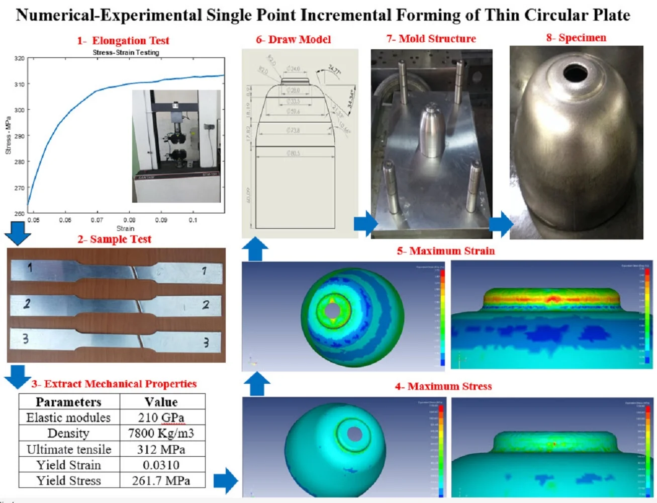
A detailed examination was conducted on a series of sheet metal specimens to evaluate various process parameters, including tool diameter, rotational speed, sheet thickness, and the resulting forming angles. The material used in the tests closely conforms to the specifications of the Japanese Industrial Standard (JIS) G3141-grade SPCE. The mechanical properties of the sheet are summarized in Table 1. For this investigation, the forming tool was fabricated from DF2 2510, a type of cold-worked tool steel. The tool's contact surface was shaped into a spherical head using a CNC lathe to ensure consistent interaction with the sheet. To enhance its durability, a normalizing heat treatment was applied to reduce internal stresses and prevent distortion or corrosion during forming. The tool surface was then ground using a precision stone center machine to achieve a uniform, smooth finish, thereby improving wear resistance. Additionally, a 20-μm-thick nitride coating was applied to the tool surface to improve its hardness and minimize wear at the tool–workpiece interface. The forming process was simulated using FormingSuite, a specialized software developed by FTI. This software is widely used in industry for analyzing and optimizing sheet metal forming operations. It supports comprehensive tasks such as cost estimation, process planning, simulation of part deformation, and post-process analysis. FormingSuite's key features include automatic mold geometry extraction, prediction of material wrinkling and thinning, and detailed cost analysis based on raw material usage and manufacturing processes. Its efficiency and accuracy in technical data processing have led to its adoption by numerous global manufacturing companies. In this study, FormingSuite was used to replicate the sheet-forming process under conditions closely matching the JIS G3141 SPCE standard to ensure realistic and reliable simulation results.
3.1. Formability limit
Based on investigations into fracture behavior and thickness variation in the SPIF process, it has been established that uniform plastic deformation continues throughout the thinning of the formed surface until fracture occurs, without any experimental evidence of necking [39]. This observation suggests that the SPIF technique inherently prevents the formation of a necking region. The absence of necking can be attributed to the nature of the process: necking typically develops along the bending path in conventional forming, but in SPIF, it is suppressed by the continuous pressure applied by the forming tool. The hemispherical tool imposes localized plastic deformation at each forming point, and the surrounding material resists the growth of localized thinning, effectively preventing necking. As a result of these unique deformation characteristics, the conventional Forming Limit Curve (FLC) becomes inadequate for predicting failure in SPIF. Instead, the Fracture Forming Line (FFL) is used to describe the material’s failure behavior under incremental forming conditions. The FFL lies above the FLC, as shown in the Fig. 2, reflecting the enhanced formability of materials in the SPIF process [40]:
In typical SPIF experiments, the ratio of tool radius to sheet thickness () commonly falls within the range of 2 to 10. Based on this ratio and the derived relationships, the slope of the corresponding forming limit line lies approximately between (–1 –1.4). This theoretical range is consistent with experimental findings. Accordingly, in the Forming Limit Curve (FLC) specific to the SPIF process, fracture tends to occur along a linear path described by , where is a material-dependent constant. Correspondingly, the thickness strain at fracture can be expressed as (). This relationship reinforces the notion that failure in SPIF is governed by a combination of principal strains, and that fracture occurs without the onset of necking, differentiating it from conventional sheet forming methods.
Fig. 2A view of the FLC position in SPIF compared to deep drawing methods [40]
![A view of the FLC position in SPIF compared to deep drawing methods [40]](https://static-01.extrica.com/articles/24756/24756-img5.jpg)
3.2. Stress and strain state
In the incremental forming process, the CDEF element, illustrated in the corresponding Fig. 3 is analyzed to evaluate the vertical forces, shear forces, and bending moments at the contact interface between the sheet and the tool tip [41]:
To derive the equilibrium equations and accurately assess the stress–strain state in the SPIF process, the following assumptions are made [42]:
1) Plane strain conditions are assumed to govern the deformation behavior.
2) The region of interest is located directly beneath the contact point between the forming tool and the sheet.
3) The overall forming process is divided into three distinct deformation zones:
– Deformation of the flat region.
– Deformation of the axisymmetric region, treated under plane strain conditions.
– Deformation of the corner region, considered to undergo biaxial tension.
4) Bending moments are neglected, and the effect of friction is assumed to be negligible.
5) The material is considered to exhibit perfectly plastic behavior, with no strain hardening incorporated into the model.
Fig. 3A view of the stress analysis position for normal and tangential stress [41]
![A view of the stress analysis position for normal and tangential stress [41]](https://static-01.extrica.com/articles/24756/24756-img6.jpg)
3.3. Tensile test
The tensile test is a standard method used to evaluate a material's mechanical response under axial loading. It provides critical information about tensile properties, including the elastic and plastic deformation ranges, elongation, Young’s modulus, ultimate tensile strength, yield point, and yield strength. In this study, tensile specimens were prepared according to the ASTM E8 standard to ensure consistency and reliability of results. The mechanical testing was conducted using a SANTAM STM-150 universal testing machine, operating at a constant crosshead speed of 10 mm/min. The obtained data were used to determine the yield stress and other relevant mechanical properties of the sheet material, which are presented in the corresponding Table 1. Fig. 4 displays the stress, strain curves generated from the tensile test, illustrating the elastic and plastic behavior of the galvanized sheet under uniaxial tension.
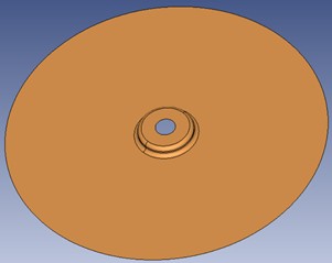
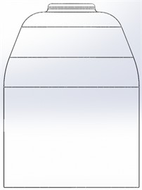
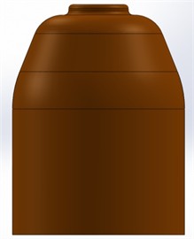
Fig. 5 presents the sample model created using the simulation software, with its corresponding mechanical properties detailed in Table 1.
Table 1Mechanical properties of thin circular Plate
Parameters | Value |
Elastic modules | 210 GPa |
Density | 7800 kg/m3 |
Ultimate tensile | 312 MPa |
Yield Strain | 0.0310 |
Yield Stress | 261.7 MPa |
4. Results and discussion
This section presents a detailed analysis of the mechanical behavior, stress–strain distribution, and failure mechanisms of galvanized steel sheets subjected to the SPIF process. Both simulation outputs from FormingSuite and experimental validation using coordinate measuring machines (CMM) and mechanical tests are integrated to evaluate the formability, accuracy, and structural integrity of the formed specimens.
Fig. 4Elongation test of sample and results
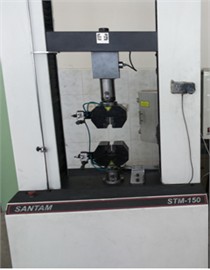
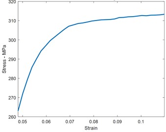
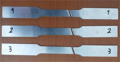
Fig. 5Thin circular galvanized plate
4.1. Identification of safe zones and stress distribution
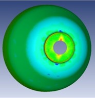
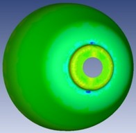
Finite Element Analysis (FEA) performed with FormingSuite revealed distinct zones of deformation, categorized into safe, low-stress, and high-stress areas. The novel contribution here lies in the coupled visualization of deformation patterns (tensile-tensile and tensile-compressive), offering a comprehensive understanding of the mechanics at various forming stages. Fig. 6 confirms the spatial stress evolution, especially in curved regions and near the forming edge. The analysis shows that stress accumulation intensifies near the tool's reversal path, where curvature changes are more abrupt. This finding is essential for toolpath optimization and failure risk reduction, particularly in parts requiring complex geometries.
4.2. Thickness strain and material flow analysis
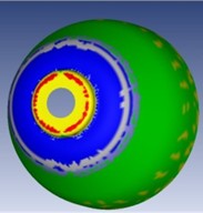
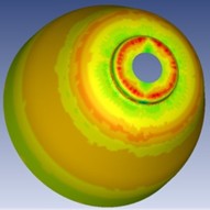
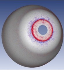
Fig. 7 demonstrates that thickness strain reaches its peak near the initial contact zone, gradually stabilizing with increasing radial distance. The minimum thickness is observed at approximately 90° of curvature, coinciding with the highest formability challenge. Notably, simulation results indicate strain localization without necking, consistent with SPIF’s suppression of classical necking mechanisms. This behavior supports the use of FFL over traditional FLC, emphasizing the uniqueness of SPIF-induced failure dynamics. The presence of a stable deformation gradient affirms the viability of the SPIF process for high-angle forming of circular geometries.
Fig. 6Sheet metal forming: a) stretching, b) qualitative effect in different regions, c) safe margin
a)
b)
c)
Fig. 7Solid mechanics, a) strain percentage of the forming operation, b) Specimen’s thickness, c) maximum principal strain, d) minimum principal strain
a)
b)

c)
d)
4.3. equivalent strain and deformation modes
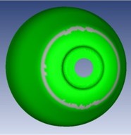
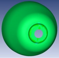
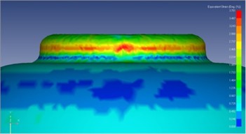
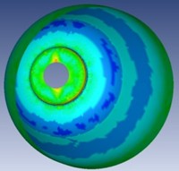
Figs. 8 and 9 illustrate the equivalent strain and stress distributions. It is observed that regions with highest strain do not always correspond to peak stress, due to the material’s local deformation accommodation. This decoupling is a novel observation and has implications for thickness prediction models and residual stress control in future SPIF strategies. These insights are pivotal for improving simulation fidelity, as they highlight the nonlinear, non-proportional nature of SPIF deformation, especially in ductile, coated materials like galvanized steel.
Fig. 8Maximum equivalent strain
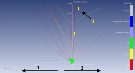
FormingSuite offers the additional capability of measuring both elongation and compression of the workpiece during the forming process. In this study, the FLD generated by FormingSuite was analyzed, as shown in Fig. 10(a). When compared to the FLD obtained from the ISF process in Fig. 10(b), the results highlight the enhanced formability characteristics enabled by the ISF method. The flexibility of the ISF process significantly improves the material’s ability to deform, often surpassing conventional forming methods. The FLD serves as a predictive tool, illustrating the material’s deformation capacity under plane strain conditions by plotting the maximum and minimum principal strains. This diagram also includes the FLC, which delineates two key regions: a safe zone, where deformation occurs without failure, and a failure zone, indicating the threshold beyond which fracture is likely. The FLC obtained through ISF demonstrates superior performance in terms of allowable strain, confirming the method’s effectiveness for developmental and prototype-level shaping applications.
Fig. 9Equivalent stress

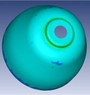
Fig. 10Elongation and compression of different points, a) top face, b) 1 – failure, 2 – FLC, 3 – safe, 4 – tension-compression, 5 – tension-tension
a)
b)
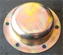
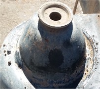
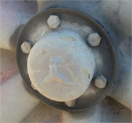
Fig. 11Experimentation, applied force, a) mold structure, and b), c) specimen
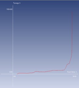
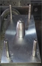
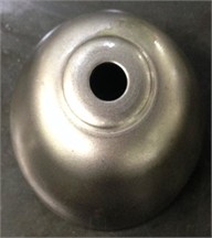
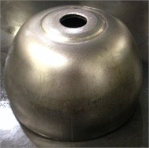
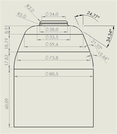
This technique has significantly enhanced formability, nearly tripling the material’s deformation limit. Fig. 11 is provided to enhance understanding of the forming process and tool interaction. As illustrated in Fig. 11(a), the shaping tool must apply varying levels of force to achieve the desired geometry, depending on the complexity of the mold structure, which is depicted in Fig. 11(d). In the initial stages of the forming process, the tool maintains vertical point contact with the sheet. As the operation progresses and the forming angle approaches approximately 90 degrees, the tool’s interaction becomes more complex, requiring greater force and control, as highlighted in Fig. 11(a). Using simulation outputs, two samples were successfully generated, shown in Fig. 11(b) and 11(c). The geometrical dimensions of these formed samples were then analyzed using the CMM, with the results presented in Fig.11(a) through 11(c). These Figs. 11 and 12 validate the accuracy of the forming process and the consistency between simulated and physical results.
Fig. 12Inverse engineering process, a) dimensions, b) CMM, c) 3D model
a)
b)
c)
5. Conclusions
This study has successfully developed and validated a numerical-experimental framework for the SPIF of thin galvanized circular plates, focusing on formability, stress-strain behavior, and failure prediction. By employing FormingSuite simulations validated through physical prototypes, the investigation demonstrated that the use of the FFL is more appropriate than conventional FLCs for SPIF applications, particularly in high-angle forming near 90°, where the risk of fracture increases. The innovation lies in correlating localized material thinning and strain distribution with real-time forming angles, enabling early identification of failure-prone regions. Future research can enhance experimental accuracy and process intelligence through the following innovations: Smart Tooling Integration: Embedding piezoelectric materials as load cells and sensors within the mold structure to develop a smart forming system [35-38]. These sensors can be connected to the DC–DC converter of the press machine for dynamic load regulation [39]. Health Monitoring: Implementing geophone sensors for real-time structural health monitoring of the workpiece during the forming process [40-41]. Advanced Simulation Techniques: Incorporating modal and vibration analysis of the formed sheet to gain deeper insight into deformation modes and dynamic response [42], as well as conducting axial crushing or impact simulations for AI-assisted thickness prediction [43-45]. Process Control Automation: Enhancing automation through the integration of intelligent control strategies such as PID, LQR, fuzzy logic, and sliding mode control. These can be synchronized with real-time sensor feedback to regulate forming force during operation [46-49]. Metamaterial Mold Design: Designing metamaterial-based molds with tailored vibrational properties to passively suppress unwanted vibrations and create frequency band gaps at natural modes [50].
References
-
S. Torsakul and N. Kuptasthien, “Effects of three parameters on forming force of the single point incremental forming process,” Journal of Mechanical Science and Technology, Vol. 33, No. 6, pp. 2817–2823, Jun. 2019, https://doi.org/10.1007/s12206-019-0528-2
-
P. Shrivastava and P. Tandon, “Microstructure and texture based analysis of forming behavior and deformation mechanism of AA1050 sheet during single point incremental forming,” Journal of Materials Processing Technology, Vol. 266, pp. 292–310, Apr. 2019, https://doi.org/10.1016/j.jmatprotec.2018.11.012
-
M. Vahdani, M. J. Mirnia, H. Gorji, and M. Bakhshi-Jooybari, “Experimental investigation of formability and surface finish into resistance single-point incremental forming of Ti-6Al-4V titanium alloy using Taguchi design,” Transactions of the Indian Institute of Metals, Vol. 72, No. 4, pp. 1031–1041, Jan. 2019, https://doi.org/10.1007/s12666-019-01577-4
-
Z. Liu and G. Li, “Single point incremental forming of Cu-Al composite sheets: A comprehensive study on deformation behaviors,” Archives of Civil and Mechanical Engineering, Vol. 19, No. 2, pp. 484–502, Mar. 2019, https://doi.org/10.1016/j.acme.2018.11.011
-
S. Basak et al., “Parameter optimization and texture evolution in single point incremental sheet forming process,” Proceedings of the Institution of Mechanical Engineers, Part B: Journal of Engineering Manufacture, Vol. 234, No. 1-2, pp. 126–139, May 2019, https://doi.org/10.1177/0954405419846001
-
P. Gupta, A. Szekeres, and J. Jeswiet, “Design and development of an aerospace component with single-point incremental forming,” The International Journal of Advanced Manufacturing Technology, Vol. 103, No. 9-12, pp. 3683–3702, May 2019, https://doi.org/10.1007/s00170-019-03622-4
-
K. U. Yazar, S. Mishra, K. Narasimhan, and P. P. Date, “Deciphering the deformation mechanism in single point incremental forming: experimental and numerical investigation,” The International Journal of Advanced Manufacturing Technology, Vol. 101, No. 9-12, pp. 2355–2366, Nov. 2018, https://doi.org/10.1007/s00170-018-3131-2
-
A. Kumar, V. Gulati, and P. Kumar, “Experimental investigation of forming forces in single point incremental forming,” in Lecture Notes in Mechanical Engineering, Singapore: Springer Singapore, 2019, pp. 423–430, https://doi.org/10.1007/978-981-13-6412-9_41
-
M. Hasanlu, “Numerical and experimental investigation on the formability of sheet metal coated by hot dip galvanizing using TPIF method,” (in Persian), Journal of Mechanical Engineering and Vibration, Vol. 11, No. 3, pp. 27–34, 2020.
-
M. Hasanlu and S. Mokary, “Practical survey in single – and two-points incremental metal forming,” (in Persian), Iranian Journal of Mechanical Engineering Transactions of the ISME, Vol. 29, No. 2, pp. 44–55, 2020.
-
A. Kumar et al., “Parametric investigation of forming forces in single point incremental forming,” Materials Today: Proceedings, Vol. 24, pp. 611–617, Jan. 2020, https://doi.org/10.1016/j.matpr.2020.04.315
-
S. Khan and S. K. Pradhan, “Experimentation and FE simulation of single point incremental forming,” Materials Today: Proceedings, Vol. 27, pp. 2334–2339, Jan. 2020, https://doi.org/10.1016/j.matpr.2019.09.123
-
Z. Wang, S. Cai, and J. Chen, “Experimental investigations on friction stir assisted single point incremental forming of low-ductility aluminum alloy sheet for higher formability with reasonable surface quality,” Journal of Materials Processing Technology, Vol. 277, p. 116488, Mar. 2020, https://doi.org/10.1016/j.jmatprotec.2019.116488
-
M. D. Vijayakumar, D. Chandramohan, and G. Gopalaramasubramaniyan, “Experimental investigation on single point incremental forming of IS513Cr3 using response surface method,” Materials Today: Proceedings, Vol. 21, pp. 902–907, Jan. 2020, https://doi.org/10.1016/j.matpr.2019.07.741
-
F. Maaß, M. Hahn, and A. E. Tekkaya, “Interaction of process parameters, forming mechanisms, and residual stresses in single point incremental forming,” Metals, Vol. 10, No. 5, p. 656, May 2020, https://doi.org/10.3390/met10050656
-
M. Murugesan and D. W. Jung, “Formability and failure evaluation of AA3003-H18 sheets in single-point incremental forming process through the design of experiments,” Materials, Vol. 14, No. 4, p. 808, Feb. 2021, https://doi.org/10.3390/ma14040808
-
V. A. Cristino, J. P. Magrinho, G. Centeno, M. B. Silva, and P. A. F. Martins, “Theory of single point incremental forming of tubes,” Journal of Materials Processing Technology, Vol. 287, p. 116659, Jan. 2021, https://doi.org/10.1016/j.jmatprotec.2020.116659
-
S. Pandre, A. Morchhale, G. Mahalle, N. Kotkunde, K. Suresh, and S. K. Singh, “Fracture limit analysis of DP590 steel using single point incremental forming: experimental approach, theoretical modeling and microstructural evolution,” Archives of Civil and Mechanical Engineering, Vol. 21, No. 3, p. 590, May 2021, https://doi.org/10.1007/s43452-021-00243-1
-
R. Esmaeilpour et al., “Experimental validation of the simulation of single-point incremental forming of AA7075 sheet with Yld2004-18P yield function calibrated with crystal plasticity model,” The International Journal of Advanced Manufacturing Technology, Vol. 113, No. 7-8, pp. 2031–2047, Feb. 2021, https://doi.org/10.1007/s00170-021-06706-2
-
C. Su et al., “Effects of forming parameters on the forming limit of single-point incremental forming of sheet metal,” The International Journal of Advanced Manufacturing Technology, Vol. 113, No. 1-2, pp. 483–501, Jan. 2021, https://doi.org/10.1007/s00170-020-06576-0
-
M. Hassan, G. Hussain, H. Wei, A. Qadeer, and M. Alkahtani, “Progress on single-point incremental forming of polymers,” The International Journal of Advanced Manufacturing Technology, Vol. 114, No. 1-2, pp. 1–26, Mar. 2021, https://doi.org/10.1007/s00170-021-06620-7
-
S. Najm, I. Paniti, T. Trzepieciński, S. Nama, Z. Viharos, and A. Jacso, “Parametric effects of single point incremental forming on hardness of AA1100 aluminium alloy sheets,” Materials, Vol. 14, No. 23, p. 7263, Nov. 2021, https://doi.org/10.3390/ma14237263
-
T. Trzepieciński, V. Oleksik, T. Pepelnjak, S. M. Najm, I. Paniti, and K. Maji, “Emerging trends in single point incremental sheet forming of lightweight metals,” Metals, Vol. 11, No. 8, p. 1188, Jul. 2021, https://doi.org/10.3390/met11081188
-
C. Suntaxi, G. Centeno, M. Silva, C. Vallellano, and P. Martins, “Tube expansion by single point incremental forming: An experimental and numerical investigation,” Metals, Vol. 11, No. 9, p. 1481, Sep. 2021, https://doi.org/10.3390/met11091481
-
N. Rosca, M. Oleksik, and L. Rosca, “Numerical-experimental study regarding the single point incremental forming process,” in MATEC Web of Conferences, Vol. 343, p. 03008, Aug. 2021, https://doi.org/10.1051/matecconf/202134303008
-
M. T. Mezher and B. Kovács, “An investigation of the impact of forming process parameters in single point incremental forming using experimental and numerical verification,” Periodica Polytechnica Mechanical Engineering, Vol. 66, No. 3, pp. 183–196, Jul. 2022, https://doi.org/10.3311/ppme.18781
-
N. Bari and S. Kumar, “Multi-stage single-point incremental forming: an experimental investigation of surface roughness and forming time,” Journal of Materials Engineering and Performance, Vol. 32, No. 3, pp. 1369–1381, Aug. 2022, https://doi.org/10.1007/s11665-022-07183-8
-
F. Maaß et al., “Forming mechanisms-related residual stress development in single point incremental forming,” Production Engineering, Vol. 13, No. 2, pp. 149–156, Dec. 2018, https://doi.org/10.1007/s11740-018-0867-3
-
F. Maqbool and M. Bambach, “Dominant deformation mechanisms in single point incremental forming (SPIF) and their effect on geometrical accuracy,” International Journal of Mechanical Sciences, Vol. 136, pp. 279–292, Feb. 2018, https://doi.org/10.1016/j.ijmecsci.2017.12.053
-
N. Bari and S. Kumar, “Multi-stage single-point incremental forming: an experimental investigation of thinning and peak forming force,” Journal of the Brazilian Society of Mechanical Sciences and Engineering, Vol. 45, No. 3, p. 137, Feb. 2023, https://doi.org/10.1007/s40430-023-04055-7
-
M. Skjoedt, N. Bay, B. Endelt, and G. Ingarao, “Multi stage strategies for single point incremental forming of a cup,” International Journal of Material Forming, Vol. 1, No. S1, pp. 1199–1202, Mar. 2008, https://doi.org/10.1007/s12289-008-0156-3
-
“HyperPhysics.”. www.hyperphysics.phy-astr.gsu.edu (accessed 2000).
-
D. Kreimeier, J. Zhu, V. Smukala, B. Buff, and C. Magnus, “CAM-solution for two robots based incremental sheet metal forming,” Key Engineering Materials, Vol. 473, pp. 889–896, Mar. 2011, https://doi.org/10.4028/www.scientific.net/kem.473.889
-
M. Hasanlu, A. Bagheri, and F. Najafi, “Optimal placement of piezoelectric S/A for active vibration control of engineering structures by using controller design,” Research Review Journal of Engineering Technology, Vol. 5, No. 4, pp. 22–44, 2016.
-
M. Hasanlu, M. Siavashi, and A. Bagheri, “Vibration attenuation Timoshenko beam based on optimal placement sensors/actuators PZT patches with LQR-MOPSO,” Iranian Journal of Mechanical Engineering Transactions ISME, Vol. 17, No. 1, pp. 26–60, 2016.
-
M. Hasanlu and A. Bagheri, “Optimal locations on Timoshenko beam with PZT S/A for suppressing 2DOF vibration based on LQR-MOPSO,” Journal of Solid Mechanics, Vol. 10, No. 2, pp. 364–386, 2018.
-
M. Hasanlu and A. Bagheri, “Intelligent control smart Timoshenko beam by using MOPSO-PID controller based on optimal location PZT patch actuator approach,” Iranian Journal of Mechanical Engineering, Vol. 20, No. 3, pp. 6–28, 2018.
-
M. Hasanlu, M. Siavashi, M. Soltanshah, and A. Bagheri, “Fuzzy-PID controller design for random vibration attenuated smart cantilever Timoshenko beam based on MOGA algorithm,” in 4th National and 2nd International Conference on Applied Research in Electrical, Mechanical and Mechatronics Engineering, 2017.
-
F. Salari and M. Hasanlu, “Optimal model predictive fuzzy control of DC-DC convertor,” Advanced Control for Applications, Vol. 6, No. 1, p. e169, Dec. 2023, https://doi.org/10.1002/adc2.169
-
M. Hasanlu, “Clearance prediction of rotary system with and without mechanical diagnosis by using artificial neural networks and particle swarm optimization,” Journal of Mechanical Engineering and Vibration, Vol. 11, No. 2, pp. 7–11, 2020.
-
M. Hasanlu, “Experimental condition monitoring of unbalanced rotary shaft based on ANFIS by using piezoelectric sensor,” Journal of Mechanical Engineering and Vibration, Vol. 11, No. 1, pp. 66–75, 2020.
-
M. Hasanlu, S. G. Mirhosseini, M. Sadeghzadeh, and A. Bagheri, “Modal analysis turboshaft test stand motor designed by using ANSYS,” Journal of Simulation and Analysis of Novel Technologies in Mechanical Engineering, Vol. 10, No. 1, pp. 781–796, 2017.
-
M. Hasanlu, M. Siavashi, and A. Bagheri, “Modeling of dynamic axial crushing of thin-walled structures by LS-DYNA and genetic programming,” in 16th International Conference of Iranian Aerospace Society, 2017.
-
M. Rostami, M. Hasanlu, and M. Siavashi, “Modeling & comparison of mechanical behavior of foam-filled & hollow aluminum tubes by LS-DYNA & introducing a neural network model,” Journal of Simulation and Analysis of Novel Technologies in Mechanical Engineering, Vol. 8, No. 4, 2015.
-
M. Hasanlu and M. Siavashi, “Nonlinear control of quadrotor trajectory with discrete H∞,” Journal of Mechanical Engineering, Automation and Control Systems, Jan. 2025, https://doi.org/10.21595/jmeacs.2024.24602
-
M. Karami Gavgani, M. Hasanlu, and M. Nikkho, “Optimal position control of nonlinear muscle based on sliding mode and particle swarm optimization algorithm,” Transactions on Machine Intelligence, Vol. 5, No. 1, pp. 37–45, Dec. 2022, https://doi.org/10.47176/tmi.2022.37
-
M. Siavashi and M. Hasanlu, “Experimental optimal control of servo-pneumatic with sliding mode and GA-fuzzy-PID-PWM,” Journal of Mechatronics and Artificial Intelligence in Engineering, Vol. 5, No. 2, pp. 199–214, Dec. 2024, https://doi.org/10.21595/jmai.2024.24656
-
M. Hasanlu, “Multivariable optimal control of fuel inlet and IGV parameters of gas turbine via PID-PSO controller in presence of noise,” Journal of Mechanical Engineering and Vibration, Vol. 10, No. 3, pp. 32–38, 2019.
-
M. Hasanlu, M. Sharif-Nejad, and G. Zarepour, “Aeroservoelastic cantilever beam by using negative velocity feedback control algorithm,” in ISME 2018, Mar. 2018.
-
M. Hasanlu, M. Siavashi, and A. Bagheri, “Free vibration analysis of metamaterial functionally graded plates with quasi-zero stiffness resonators,” Noise and Vibration Worldwide, Vol. 54, No. 2-3, pp. 108–121, Jan. 2023, https://doi.org/10.1177/09574565231154248
About this article

The authors have not disclosed any funding.
The datasets generated during and/or analyzed during the current study are available from the corresponding author on reasonable request.
The authors declare that they have no conflict of interest.
