Abstract
In order to explore the application feasibility and effective gain of shaped charge jet under multi-point initiation system, the jet forming characteristics of 40 mm diameter shaped charge under multi-point initiation mode were analyzed, and the influence rules of the number of initiation points and initiation radius on jet parameters were obtained. The simulation results of jet penetrating cylindrical shell covered charge show that the multi-point initiation system can effectively improve the jet tip velocity and the length of the jet, which can effectively improve the impact initiation ability of the shell charge.
Highlights
- The jet forming characteristics of 40mm diameter shaped charge under multi-point initiation mode were analyzed.
- The influence rules of the number of initiation points and initiation radius on jet parameters were obtained.
- The capability of jet penetrating cylindrical shell covered charge under multi-point initiation mode was evaluated.
1. Introduction
Shaped charge jet (SCJ) is a kind of condensed high-speed penetrator, which has high speed and is widely used in penetrating fortifications, armor targets, destroying unexploded ordnance and so on [1]. In practical application, the diversity of targets and the lightweight of warhead require the shaped charge to reduce its weight and size as much as possible when used to destroy targets, which poses a severe challenge to the design of warhead. By changing the number of initiation points, the multi-point initiation system can increase the detonation pressure in the explosive and also change the collapse angle, thus affecting the stress state of the liner and its forming [2], which becomes a potential choice to improve the characteristics of SCJ. At present, multi-point initiation system is widely used in rod penetrator and explosively formed projectile, but the application is limited due to the sensitivity of shaped charge jet to initiation synchronization [3].
In this paper, according to a typical shaped charge structure of 40 mm caliber, the SCJ forming characteristics under different initiation modes were analyzed by numerical simulation. The influence of the number of initiation points and the initiation radius on the characteristic parameters of jet was obtained, and a better initiation mode is optimized. The numerical simulation of penetrating cylindrical shell covered charge was carried out, so as to provide reference for the application of multi-point initiation system in small cone angle shaped charge, and also a basis for the application of multi-point initiation system in the destruction of unexploded ordnance.
2. Numerical simulation model and material parameters
2.1. Numerical simulation model
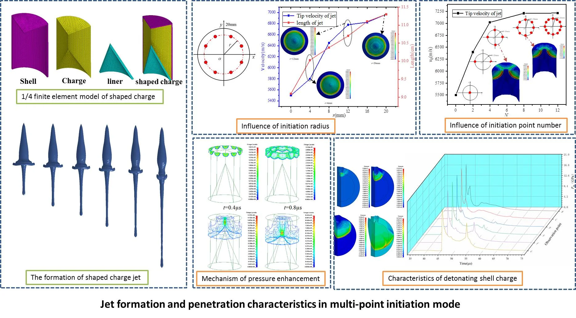
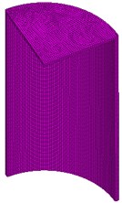
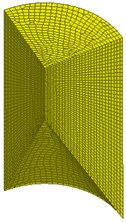
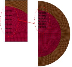
The shaped charge used in this paper was composed of main charge, liner and shell. The main charge is 40 mm in diameter, 60 mm in height and 40° in cone angle. The main charge was 8701. The liner was made of copper with a wall thickness of 1.6 mm. The shell was 2 mm thick and made of aluminum alloy. The 8-node polyhedral solid element in LS-DYNA software (Solid164) was used in the calculation model. The air domain, explosive and shaped charge structure adopt Euler element, and the shell and charge in cylindrical shell charge used Lagrange mesh. Thus, the model was calculated by fluid structure coupling method. At the same time, a 1/4 model was established to simplify the calculation. Fig. 1 shows the 1/4 finite element model of shaped charge and its components.
Fig. 11/4 finite element model of shaped charge and its components
a) Shell
b) Charge
c) Liner
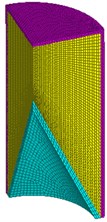
d) Shaped charge
2.2. Material model and parameters
In order to better simulate the phenomena of liner collapsing, forming and perforating when interact with the shell charge, Johnson-cook material model with failure fracture criterion [4] was selected for liner and shell of charge, which takes into account the strain hardening, strain rate and temperature effect of material.
For von Mises yield stress model, the material yield stress is expressed as follows:
where: is equivalent plastic strain, is relative equivalent plastic strain rate, is relative temperature, is yield stress, is strain hardening, is strain hardening index, is strain rate correlation factor, is temperature correlation factor.
The expression of the fracture strain is expressed as follows:
where is the damage to a material element, is the increment of accumulated plastic strain, and is the accumulated plastic strain to failure under the current conditions of stress triaxiality, strain rate and temperature. Failure occurs when 1. Material parameters selected from reference [5].
The explosive of shaped charge was 8701, HIGH_EXPLOSIVE_BURN material model and JWL equation of state were selected, see in reference [3] for specific parameters. The explosive in the shell charge was TNT and ELASTIC_PLASTIC_HYDRO material model and IGNITION_AND_GROWTH_OF_REACTION_IN_HE were selected for the study on shock initiation characteristics. For air, Null material model and LINEAR_POLYNOMIAL equation of state were used. The material parameters were obtained from reference [5].
3. Analysis of numerical simulation results
3.1. Analysis of jet forming process
The typical forming progress of SCJ was shown in Fig. 2. The initiation mode was center point initiation. From the numerical simulation results, it can be seen that at about 10.4 μs after initiation, most of the liner materials have completed the movement to the symmetrical plane. At this time, the jet after collision redistributes the energy. The jet gradually forms at the head, and the pestle body forms at the tail. Due to the velocity difference between the head and tail, the jet was stretched. The final shape of jet formed at about 34.6 μs after initiation, and the velocity of jet head was about 5500 m/s.
Fig. 2Shaped charge jet forming process with center point initiation

a)0 µs
b) 12.6 µs
c)71 µs
a)21.2 µs
d)34.6 µs
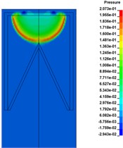
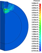
Fig. 3 shows the propagation process of detonation front in the case of center point initiation. When 0.2 μs, the spherical detonation front grows steadily and propagates to the unexploded explosive. When 2.2 μs, the spherical detonation wave reaches the top of the liner and starts to impact and squeeze the liner; the element pressure on the top of the liner suddenly jumps to 20.7 GPa. When 3.2 μs, the detonation products attached to the detonation wave continue to squeeze the liner, and the detonation wave begins to impact and squeeze the circumferential shell. When 7.6 μs, the peak pressure of the detonation front is 31.6 GPa, and the converged detonation wave moves towards the liner direction. After a series of complex interactions, the new wave system and detonation products will have a new round of impact and extrusion on the liner, and the maximum front pressure is 38.9 GPa.
Fig. 3The propagation process of detonation front of center point initiation
a) 0.2 µs
b) 2.2 µs
c) 3.2 µs
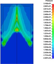
d)7.6 µs
3.2. Influence of initiation point
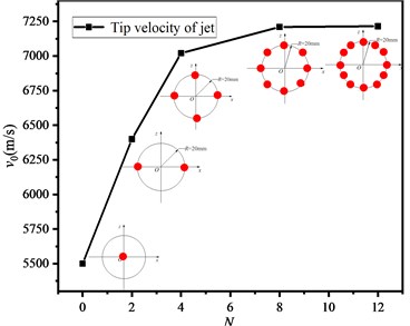
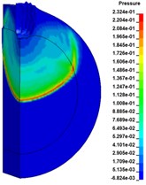
Based on the above model, numerical simulation under four initiation modes with 2, 4, 8 and 12 initiation points () was carried out respectively. The initiation points were distributed in a ring shape and the initiation radius was 20 mm. Fig. 4 shows the propagation state of detonation wave in charge and the pressure distribution on the upper surface of the liner.
When multi-point initiation was adopted, the detonation wave would converge and collide in charge, and the peak pressure on the upper surface of the liner was 23.68 GPa, 26.30 GPa, 26.74 GPa and 25.51 GPa respectively, which were significantly larger than that of single point initiation of 17.13 GPa. The distribution of detonation wave initiated by two points was asymmetric (Fig. 4(d)). With the increase of the number of initiation points, the pressure distribution on the upper surface of the liner was more uniform, which was closer to the effect of ring initiation.
Fig. 4The propagation process of detonation front of multi-point initiation
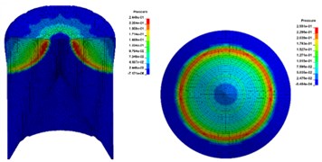
a)12

b)8
c)4
d)2
Fig. 5 is the variation of jet tip velocity with initiation point. The initial velocity of jet tip increases with the number of initiation points. Compared with single point initiation, the increment of initial velocity of jet head can reach 980 m/s, and the maximum increase amplitude of jet tip velocity can reach 15.63 %.
Fig. 5The variation of jet tip velocity with initiation point
3.3. Influence of initiation radius
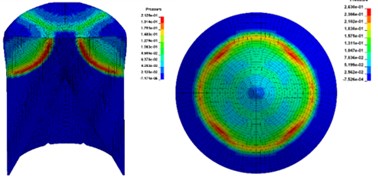
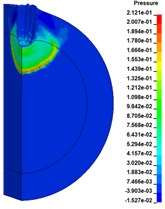
In order to explore the influence of distribution radius of multiple initiation points on jet performance, the circular distribution radius of eight initiation points was selected, as shown in Fig. 6. The distribution radius is 4 mm, 8 mm, 12 mm, 16 mm and 20 mm respectively.
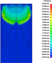
By extracting the pressure and impulse data of element (H5601) on the top of liner and drawing the curve in Fig. 7, it shows that the maximum pressure and impulse of element H 5601 are increasing with the increase of initiation radius. We can get enlightenment from the pressure propagation characteristics in Fig. 8.
As shown in the Fig. 8, the detonation wave generated at each initiation point was superimposed for the first time at 0.8 μs, and then gradually converged to the bottom of the charge and the unexploded area under the reflection of the shell; the detonation wave was superimposed at 2.6 μs to form a high pressure area, with an instantaneous high pressure of 119 GPa; as the high pressure superposition area of the initiation ring propagates downward along the central axis and acts on the charge. The top of the liner was then crushed and shaped.
Fig. 6Schematic diagram of initiation point position and pressure nephogram of liner (t= 6 μs)
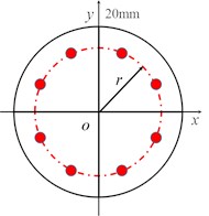
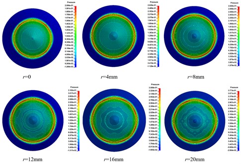
Fig. 7The variation of maximum pressure and impulse at observation point with r (t= 6 μs)
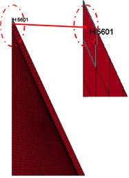
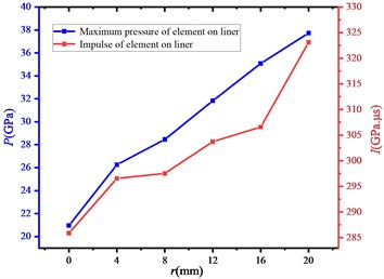
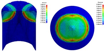
Fig. 8Peak pressure variation of explosive detonation front under r= 20 mm condition
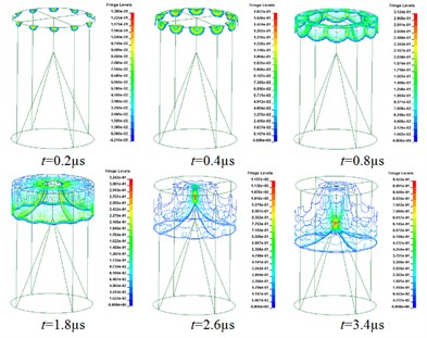
Fig. 9The change of jet tip velocity and jet length
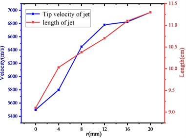
As the radius of the initiation ring becomes smaller, that is, the initiation point is closer to the central axis, and the detonation wave does not grow sufficiently at the time of the first superposition, the instantaneous high pressure will decrease, and the overall impulse acting on the liner will also decrease. The change of jet tip velocity and jet length recorded in Fig. 9 can well reflect this rule. Theoretically, the bigger the radius of initiation ring is, the better jet state can be obtained.
4. Impact initiation of jet on cylindrical shell covered charge
In order to study the impact initiation ability of SCJ to the charge with shell, the numerical simulation of SCJ detonating charge with shell under single initiation was carried out. The numerical model was shown in Fig. 10. It is necessary to keep the shape intact and the overall characteristics in a good state before the SCJ impinging into the cylindrical shell. Through the numerical analysis in the last section, standoff distance was selected, namely 120 mm.
Fig. 10Schematic diagram of shaped charge impacting into cylindrical shell
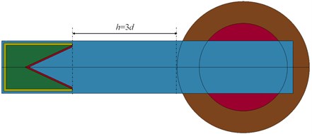
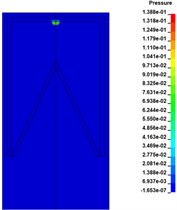
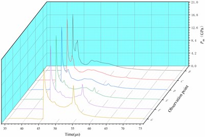
Fig. 11 shows the initiation process of 10 mm thick cylindrical shell covered charge by SCJ. Six observation points (#319005, #319083, #319161, #319239, #319317, #319315) are selected along the axis of the charged charge, shown in the Fig. 12, to record the pressure. The pressure of the charge has exceeded the critical initiation pressure of TNT by 10.4 GPa, it is considered that the charge has been successfully initiated. The shell has not been broken down, which indicates that the strong shock wave produced by the jet impinging on the shell is the shock initiation mechanism.
Fig. 11Detonation growth process of covered charge
a)47.6 µs
b)48.8 µs
c)51.0 µs
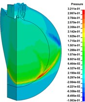
d)53.8 µs
Fig. 12Observation point diagram and pressure curve
5. Conclusions
In this paper, the analysis of SCJ forming and penetrating into shell covered charge under multi-point initiation mode was carried out, the detailed process of jet forming was revealed, and the reliable gain of multi-point initiation mode on penetration of SCJ was obtained. The conclusions are as follows:
1) The tip velocity of jet increases with the number of initiation points. Compared with single point initiation, the maximum increase amplitude of jet tip velocity can reach 15.63 %.
2) The increase of initiation radius is helpful to the full growth of detonation wave before collision, which can effectively improve the jet velocity. Under the eight point initiation mode, the jet tip velocity of full-scale initiation is 14.2 % higher than that of single point initiation.
3) The SCJ formed by single point initiation could initiate 10 mm thick shell covered charge through shock initiation mechanism.
References
-
Hansenberg Divad Consequences of Coaxial Jet Penetration Performance and Shaped Charge Design Criteraia. Naval Postgraduate School, Monterey, California, 2010.
-
Li W., Wang X., Li W. The effect of annular multi-point initiation on the formation and penetration of an explosively formed penetrator. International Journal of Impact Engineering, Vol. 37, Issue 4, 2010, p. 414-424.
-
Liu Jian-Ging, et al. Formation of explosively formed penetrator with fins and its flight characteristics. Defense Technology, Vol. 10, Issue 2, 2014, p. 119-123.
-
Johnson Gordon R., Cook William H. Fracture characteristics of three metals subjected to various strains, strain rates, temperatures, and pressures. Engineering Fracture Mechanics, Vol. 21, 1985, p. 31-48.
-
LS-DYNAR Keyword User’s Manual V971. Livermore Software Technology Corporation (LSTC), Livermore, 2012.
About this article

