Abstract
Conductive rolling rings utilize a rolling electrical contact mechanism for power and signal transmission, effectively mitigating friction, enhancing transmission efficiency, and extending service life compared to traditional sliding rings. This study investigates the kinematics of the flexible ring using the simulation method. By analyzing velocity contour plot and decomposing velocity vectors, the superposition characteristics of the ring's spin-orbit coupled motion are elucidated. Simulation results indicate that the linear velocity peaks at 363 mm/s at the inner ring interface and approaches zero at the outer ring. Furthermore, the slide-to-roll ratio was calculated to quantify rolling performance. Across deformation levels ranging from 0.3 mm to 0.7 mm, the SRR remains exceptionally low (0.0008-0.0033). This confirms minimal relative slip at the contact interface, demonstrating an ideal pure rolling friction state. These findings provide a reliable theoretical and simulation basis for structural optimization, friction pair matching, and practical applications of conductive rolling rings.
1. Introduction
Conductive rolling rings adopt rolling electrical contact to mitigate severe wear and short service life of conventional sliding rings, thus widely used in aerospace industries. Existing research has developed design and fabrication methods for elastic rings under harsh environments to support practical engineering applications [1]-[3]. By replacing sliding contact with rolling contact, these rings significantly reduce friction and offer superior transmission efficiency and longevity. With modern technological advancements, the research significance of conductive rolling rings has become increasingly prominent [4], [5].
Squires [6] developed a space-specific roll-ring, validating its reliability through a 234-million-revolution accelerated test. The results confirmed the system's dynamic contact resistance and signal stability, establishing a robust design framework for deep-space equipment. Weber [7] conducted comparative experiments between conductive roll rings and traditional brush slip rings. By analyzing friction loss, contact resistance fluctuation, and transmission efficiency, the study highlighted the superior wear resistance and adaptability of rolling contact structures for aerospace applications. Ferreira [8] established a test platform to compare the triboelectric behaviors of flexible rolling rings and metal wire rings. The study quantified differences in wear loss and signal transmission, specifically analyzing the influence of coating surface states on the contact performance of rolling conductive pairs. Furthermore, Yang [9] investigated failure mechanisms within the contact regions, linking microstructural evolution under current-carrying friction to interface damage progression. Similarly, Chen [10] examined the lifespan of aerospace conductive rolling rings, identifying interface damage evolution as the primary factor limiting long-term stable performance.
Previous studies fail to precisely characterize the 3D elastic deformation and contact behavior of flexible rings, without mechanical verification of pure rolling stability. Herein, a multi-physics simulation platform is built to quantify the spin-orbit velocity ratio of 0.0016. This micro-kinematic verification validates the structural reliability and uncovers the motion mechanism of high-power conductive rolling rings.
2. Establishment of the simulation model
2.1. 3D modeling and meshing of the power rolling ring
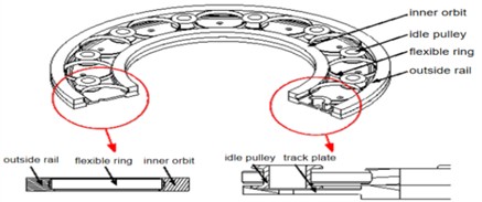
Simulation analyses are conducted using COMSOL Multiphysics, with the roll-ring model depicted in Fig. 1. The flexible ring is modeled as structural steel ( 200 GPa, 0.3, 7850 kg/m3) and meshed with tetrahedral elements of minimum size 0.5 mm, refined to 0.2 mm at contact interfaces. The outer conductive ring is fully fixed, while the inner ring rotates at 60 rpm. Frictionless contact is defined between the flexible ring and outer ring, whereas frictional contact (0.05) is set between the flexible ring and inner ring. To simulate varying load conditions, radial interferences of 0.3 mm, 0.5 mm, and 0.7 mm are applied as preloads. Power transmission is achieved through rolling friction between the flexible ring and the outer ring.
Fig. 1 overall design of the power rolling ring. Power transmission is realized via rolling friction between the flexible ring and the fixed outer conductive ring.
Fig. 1Power rolling ring design model
2.2. Analysis of the speed of the power roller ring
2.2.1. Analysis of power roll ring speed
Fig. 2(a) illustrates the kinematic analysis and the composite motion principle of the flexible ring based on its geometric configuration. Fig. 2(b) presents the velocity contour plot, revealing a distinct gradient distribution during operation. The velocity peaks at 363 mm/s at contact point A (inner ring interface) and gradually decreases along both paths (A→B→C→D→E and A→K→G→F→E), approaching zero at contact point E (outer ring interface). This distribution results from the superposition of spin and orbital velocities under pure rolling conditions, where the two velocities are equal in magnitude but vary in directional alignment depending on the position.
Furthermore, the velocity vector analysis in Fig. 3 reveals the velocity superposition mechanism at characteristic points: 1. Point A: The spin velocity () and orbital velocity () are in the same direction, resulting in the maximum linear velocity . 2. Points B and K: The angle between and is 45°, yielding resultant velocities and that are lower than . 3. Points C and G: With a 90° angle between and , the resultant velocities and decrease further. 4. Points D and F: As the angle between and increases to 135°, the resultant velocities and continue to drop. 5. Point E: The spin velocity () and orbital velocity () are in opposite directions, resulting in a near-zero linear velocity 0. The above points summarize the velocity superposition mechanism of the flexible ring.
Fig. 2Kinematic analysis schematic and flexible ring velocity contour plot
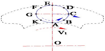
a) Kinematic analysis schematic
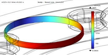
b) Flexible ring velocity contour plot
Fig. 3Velocity decomposition along flexible rings
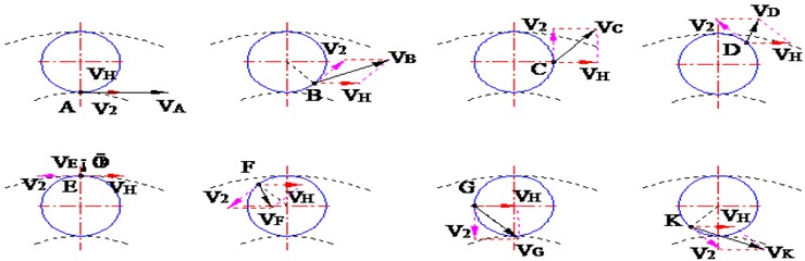
The velocity synthesis mechanism was analyzed in conjunction with the velocity vector diagram (Fig. 4(a)). Based on vector addition principles, the theoretical velocity trajectory aligns well with actual conditions. To further validate the model, the results were compared with the operational contour plots of the flexible ring (Fig. 4(b)) to verify kinematic characteristics under pure rolling. The results show excellent agreement with theoretical predictions, demonstrating high reliability.
Fig. 4Flexible ring kinematics
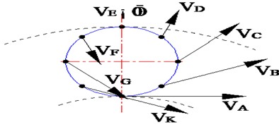
a) Velocity vectors
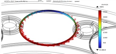
b) Contours plot
2.2.2. Calculation of the flexible loop's rotational speed
To address the challenge of velocity extraction under coupled rotation and revolution, we adopted Wang Q. et al.’s [11] flexible ring method on an elastic foundation. The instantaneous resultant velocity is precisely acquired via vector summation of - axis velocities and probe monitoring at key locations.
For precise dynamic calculation, the velocity is quantified using the inner ring speed (), flexible ring rotation speed (), and revolution speed (). Contour analysis reveals that the maximum velocity occurs at the inner contact point (), while the minimum occurs at the outer contact point (). By extracting the global maximum and minimum velocities in the plane, and can be decoupled and solved simultaneously.
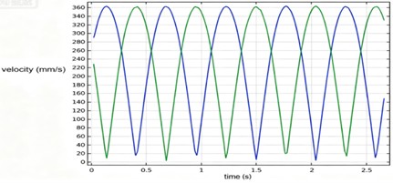
To validate accuracy, two probes on the flexible ring monitored real-time velocities. As shown in Fig. 7, both points exhibit periodic oscillations with maxima below 370 mm/s, indicating stability. The strong agreement between simulation data and theoretical calculations confirms the method's reliability.
Fig. 5Flexible ring and velocity curve diagram
2.2.3. Calculation of the rolling ratio for flexible rolling rings
The rotation and revolution velocities of the flexible ring are thus obtained. The inner contact velocity () equals the product of the inner ring's rotational speed and radius. The sliding velocity is the difference between and the flexible ring velocity. Accordingly, the slide-to-roll ratio is given by:
Table 1Flexible circular velocity and roll slip ratio
Deflection | Internal conductive ring line velocity () | Linear velocity of the flexible ring during its rotation () | Linear orbital velocity of the flexible ring during revolution () | Sliding ratio |
0.3 | 362.84 | 181.15 | 181.22 | 0.0008 |
0.5 | 363.65 | 181.48 | 181.59 | 0.0016 |
0.7 | 364.12 | 181.75 | 182.05 | 0.0033 |
As shown in the table, the flexible ring's revolution velocity slightly exceeds its rotation velocity, and their sum is marginally below the inner ring velocity. The very low slide-to-roll ratio indicates negligible macroscopic sliding, confirming near-ideal pure rolling. The slight increase in this ratio under higher loads further demonstrates kinematic stability. These results validate that the proposed velocity vector synthesis method accurately captures the flexible ring’s true motion, providing a reliable basis for dynamic analysis.
3. Conclusions
Unlike 2D simplified or single-component theoretical models, this study establishes a 3D full-structure simulation model to accurately replicate the assembly and kinematic constraints of the conductive slip ring system, yielding results highly consistent with practical engineering conditions.
The flexible ring exhibits a distinct velocity gradient, peaking at 363 mm/s at the inner contact and approaching zero at the outer contact. Analysis across varying deformations reveals an exceptionally low slide-to-roll ratio of 0.0008-0.0033, which increases only marginally with load. These results confirm an ideal pure rolling state and excellent kinematic stability, providing a solid theoretical basis for future structural optimization.
References
-
B. D. Hall and D. L. Jones, “Roll ring assemblies for the Space Station,” in 27th Aerospace Mechanisms Symposium, pp. 347–362, 1993.
-
R. M. Weber, “Brushless slip ring for high power transmission,” in Proceedings of the 13th European Space Mechanisms and Tribology Symposium, 2009, https://doi.org/10.2514/6.2009-6673
-
T. Chen et al., “Effect of elastic contact force on tribological characteristics of current-carrying roll rings in rotating conductive joints,” Tribology Transactions, Vol. 66, No. 1, pp. 175–184, 2023, https://doi.org/10.1080/10402004.2022.2153773
-
Chen J. et al., “Numerical research on the electrical contact model and thermal analysis of the Roll-Ring,” in 2nd International Conference on Electric Power Equipment – Switching Technology (ICEPE-ST), pp. 1–4, 2014, https://doi.org/10.1109/icepe-st.2013.6804345
-
J. Chen, F. Yang, K. Luo, M. Zhu, Y. Wu, and M. Rong, “Experimental investigation on the electrical contact behavior of rolling contact connector,” Review of Scientific Instruments, Vol. 86, No. 12, p. 125110, Dec. 2015, https://doi.org/10.1063/1.4938091
-
J. L. Squires, “Design and testing of a Roll-Ring,” in Proceedings of the 18th European Space Mechanisms and Tribology Symposium (ESMATS), 2019.
-
R. M. Weber, “Tribological and electrical performance comparison between rolling-contact roll-rings and conventional brush slip rings,” in Proceedings of the 12th European Space Mechanisms and Tribology Symposium (ESMATS), 2007.
-
C. Ferreira, A. Brézard-Oudot, M. Isard, S. Noël, F. Houzé, and P. Testé, “Electrical and tribological behaviour of gold/gold sliding contacts of the wire/ring type for slip ring applications,” in 2023 IEEE 68th Holm Conference on Electrical Contacts (HOLM), pp. 1–7, Oct. 2023, https://doi.org/10.1109/holm56075.2023.10352303
-
T. Yang et al., “Investigation of current-carrying tribological properties and mechanisms of in-situ 2TiB2/Cu-3B composite,” Tribology International, Vol. 207, p. 110612, 2025, https://doi.org/10.1016/j.triboint.2025.110612
-
T. Chen et al., “Current-carrying contact character and wear behavior of an elastic ring at different rolling speeds,” Engineering Failure Analysis, Vol. 131, p. 105825, Oct. 2021, https://doi.org/10.1016/j.engfailanal.2021.105825
-
Q. Wang, Y. Zhao, F. Lin, H. Fu, and X. Du, “Research on vibration characteristics and its key influencing factors of new mechanical elastic wheel,” Journal of Vibroengineering, Vol. 18, No. 8, pp. 5337–5352, Dec. 2016, https://doi.org/10.21595/jve.2016.16952
About this article

The authors would like to thank the Science and technology development plan project of Jilin province No. YDZJ202401326ZYTS and the Gan-Po Talent Support Program of Jiangxi Province No. 20243BCE51035.
The datasets generated during and/or analyzed during the current study are available from the corresponding author on reasonable request.
The authors declare that they have no conflict of interest.

