Abstract
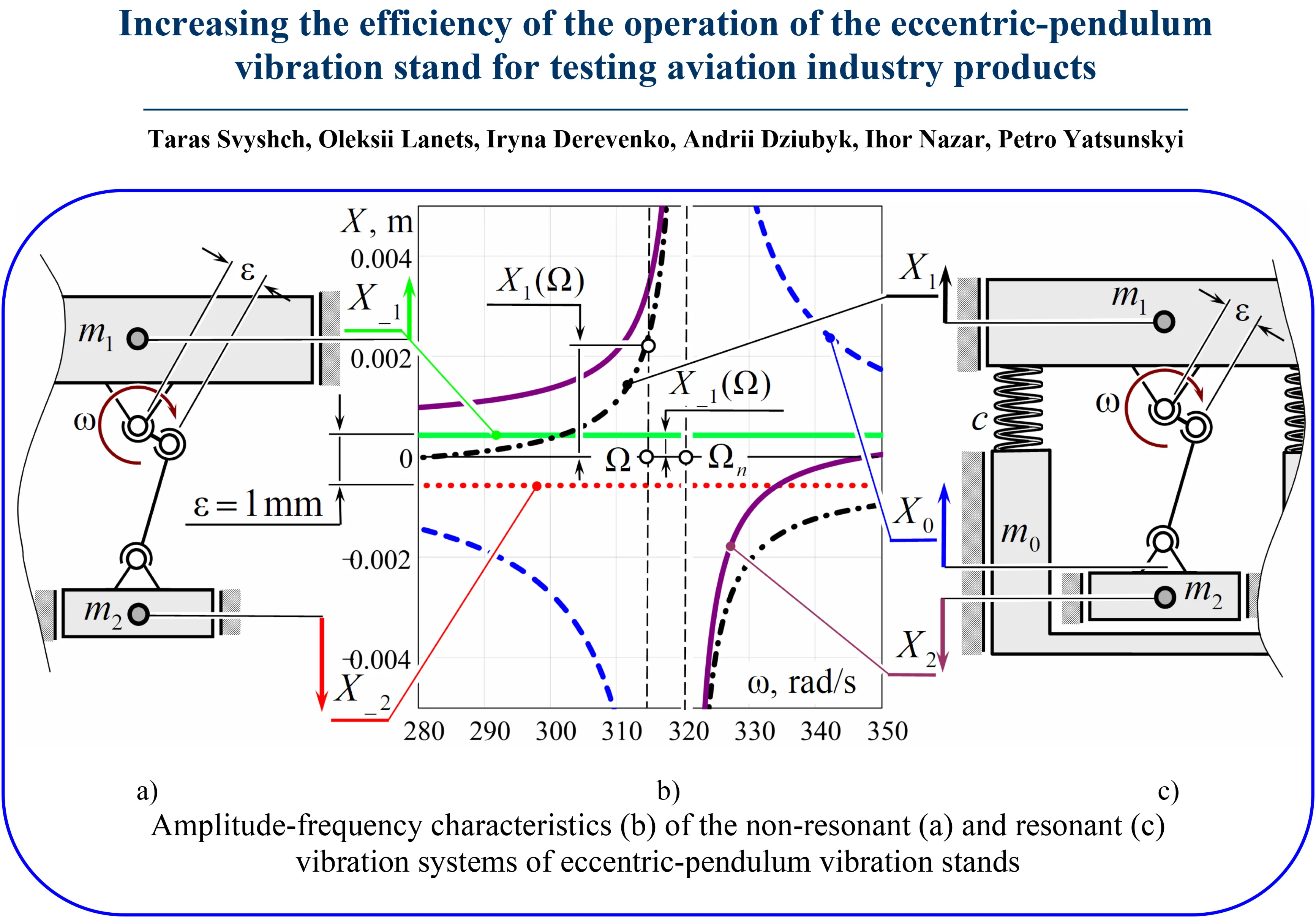
In this article, the authors present an approach that makes it possible, by making minimal changes to the design of an eccentric-pendulum vibration stand, to increase its operating efficiency. To achieve this, the non-resonant vibration system of the vibration stand was converted into a resonant one. The resonant elastic unit was located in place of the vibration isolators that were installed on the frame. The frame itself was placed on vibration isolators. This approach allowed the non-resonant vibration system to be converted into a resonant one, where the functions of one of the oscillating masses were performed by the frame. The mass of the entire structure remained practically unchanged, and the operating efficiency of the newly formed vibration system increased significantly. To confirm this, the amplitude-frequency characteristics of both vibration systems were analyzed. It was proved that the resonant vibration system operating in near-resonant conditions exhibits significantly higher working-body vibration amplitudes. It was assumed that the excitation forces acting on the oscillating masses, and therefore their oscillations, followed a harmonic law. Thus, the results presented in this article confirmed the possibility of increasing the vibration amplitudes of a non-resonant eccentric-pendulum vibration stand by converting the non-resonant vibration system into a resonant one, while requiring only minimal design changes and, consequently, minimal resources.
Highlights
- The approach proposed by the authors makes it possible to increase the operating efficiency of the non-resonant eccentric-pendulum vibration stand while requiring only minimal changes to its design.
- To achieve this, the non-resonant vibration system of the vibration stand was converted into a resonant one, in which a resonant elastic unit was installed in place of the vibration isolators. In this case, the frame was converted into an oscillating mass.
- The mass of the entire structure remained practically unchanged, and the operating efficiency of the newly formed vibration system increased significantly.
1. Introduction
Currently, in industry, various vibration stands and vibration machines are used to test products under alternating cyclic loads or to perform various technological operations related to vibration hardening or vibration compaction of products. In general, such equipment can be divided into resonant and non-resonant systems. Each type has its own advantages and disadvantages. Thus, non-resonant vibration equipment is structurally simple and inexpensive to maintain, while resonant equipment is structurally more complex and more expensive. At the aircraft structural level, fatigue strength and damage tolerance requirements are governed by FAA 14 CFR Part 23/25, EASA CS-23/CS-25, and the military standard MIL-HDBK-1530, which establishes the Aircraft Structural Integrity Program (ASIP) framework for ensuring the aircraft structural integrity.
A large number of scientists have contributed to the development of both types of vibration equipment. Current investigations are directed toward broadening the functional potential of vibration technologies by introducing novel designs of vibratory equipment [1] and by improving the efficiency of existing systems through the optimization of their operating parameters [2]. Considerable research has also been dedicated to determining optimal trajectories of motion for vibrating working elements [3], together with refining amplitude-frequency responses to ensure stable resonant conditions and maximize system performance [4].
Another important area of research concerns the dynamic characteristics of inertial vibration exciters [5], where various approaches have been proposed to enhance their functional and operational performance [6]. Mathematical modeling continues to play a central role in vibration engineering, serving as a powerful tool for analyzing, predicting, and optimizing the behavior of vibration systems [7]. At the same time, ongoing studies address the dynamic processes occurring in vibratory machines [8], examine the synchronization phenomena of inertial vibration exciters [9], and develop advanced control methodologies aimed at improving system stability, energy efficiency, and operational reliability [10].
Studies [11] and [12] investigated the possibility of modernizing vibration technological equipment by converting two-mass resonant vibration systems into three-mass inter-resonant vibration systems. This allowed the operating efficiency of such equipment to be increased. Study [13] proposed an approach for converting single-mass vibration machine designs into two-mass resonant ones. The studies presented in [14, 15] are of particular interest, as they propose a methodology for developing inter-resonant vibration machines equipped with eccentric drives. However, implementing these modifications requires significant structural changes, namely the introduction of an additional oscillating mass into the vibration system. This requires significant time and financial resources.
In this article, the authors present an approach that makes it possible to increase the operating efficiency of an eccentric-pendulum vibration stand by making minimal changes to its design.
2. Description of the vibration system of a non-resonant eccentric-pendulum vibration stand
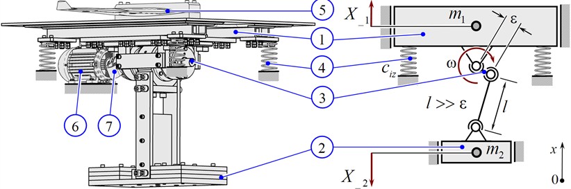
Fig. 1(a) shows the vibration system of a non-resonant vibration stand of the eccentric-pendulum type [16]. The active oscillating mass 1, with an inertia of , is connected to the reactive oscillating mass 2 through a shaft 3 with eccentricity . The reactive oscillating mass 2, with an inertia of , is freely suspended on the eccentric shaft 3 and acts as a pendulum. The entire vibration system is installed on the foundation through vibration isolators 4, having a stiffness coefficient of . The vibration isolators are fixed to the lower part of the active oscillating mass 1. The glider wing 5 is rigidly fixed to the active oscillating mass 1, serving as the working body. This vibration stand was developed specifically to study the vibration resistance of the glider wing.
The rotational motion of the rotor of the electric motor 6 with an angular frequency is transmitted through the petal clutch 7 to the shaft 3 with eccentricity . As a result, the oscillating masses 1 and 2 are set in motion. To simplify the presentation of the material, it is assumed that the motions of both oscillating masses occur along a linear coordinate (Fig. 1(b)). The influence of properly selected vibration isolators on the dynamic behavior of the system is negligible. Accounting for the vibration isolators changes the calculated vibration amplitudes by no more than 3 % [13]. Therefore, the stiffness of the vibration isolators is neglected in the subsequent analysis. In this case, the amplitudes of the oscillations of masses 1 and 2 in the frequency domain are determined using the dependencies [13]:
Analyzing Eq. (1) and (2), it can be observed that the relative amplitude of the oscillations of both masses remains constant over the entire frequency range . In order to increase the efficiency of the functioning of the non-resonant eccentric-pendulum vibration stand (Fig. 1), it was decided to convert its vibration system into a resonant one, using minimal structural changes.
Fig. 13D model and simplified schematic diagram of the non-resonant eccentric-pendulum vibration stand, where: 1 – active oscillating mass; 2 – reactive oscillating mass in the form of a pendulum; 3 – shaft with eccentricity ε; 4 – vibration isolators; 5 – glider wing cantilever-mounted on the active oscillating mass 1; 6 – electric motor; 7 – petal clutch
3. Description of the vibration system of the resonant eccentric-pendulum vibration stand
Most vibration equipment is installed on the foundation through the frame. The frame serves solely as a supporting structure and does not participate in the dynamic processes. This also applies to the vibration stand in Fig. 1. However, if instead of vibration isolators connecting the vibration system to the frame, resonant elastic elements 9 are replaced (Fig. 2), and the frame 8 is installed on vibration isolators 4, then a resonant vibration system can be obtained. In this case, the frame 8 will perform the function of oscillating mass and will be set in motion kinematically, namely kinematically by the movement of the oscillating mass 1.
Fig. 23D model and simplified schematic diagram resonant eccentric-pendulum vibration stand, where: 8 – frame; 9 – resonant elastic elements, and the content of the remaining items is the same as in Fig. 1
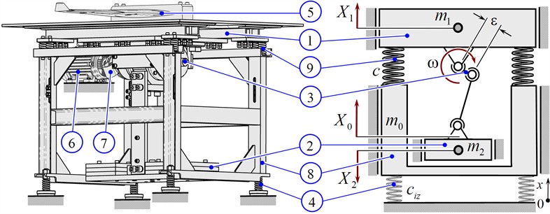
To implement the resonant mode of operation in the vibration system in Fig. 2, it is necessary that the stiffness coefficient of the elastic elements 9 be set according to the expression [13]:
where – inertial value of frame 8; – angular frequency of forced oscillations (angular frequency of rotation of shaft 3 with eccentricity in steady-state modes); – resonant tuning of the vibration system.
The amplitudes of oscillations of masses 1, 2 and 8 in the frequency domain for the vibration system in Fig. 2 will be determined according to the expressions [13]:
where .
4. Comparison of characteristics of vibration systems
Let us consider the case in which the parameters of the vibration systems have the following values: 105 kg; 200 kg; 154 kg; 0.001 m; 314 rad/s; 0.98. In this case, using Eqs. (1), (2) together with Eqs. (4)-(6), the amplitudes of the mass oscillations in the frequency domain for the non-resonant and resonant, respectively, are of vibration systems (Fig. 1 and Fig. 2, respectively), can be obtained, as shown in Fig. 3.
Fig. 3Amplitude-frequency characteristics of the non-resonant and resonant vibration systems of eccentric-pendulum vibration stands shown in in Fig. 1 and Fig. 2, respectively
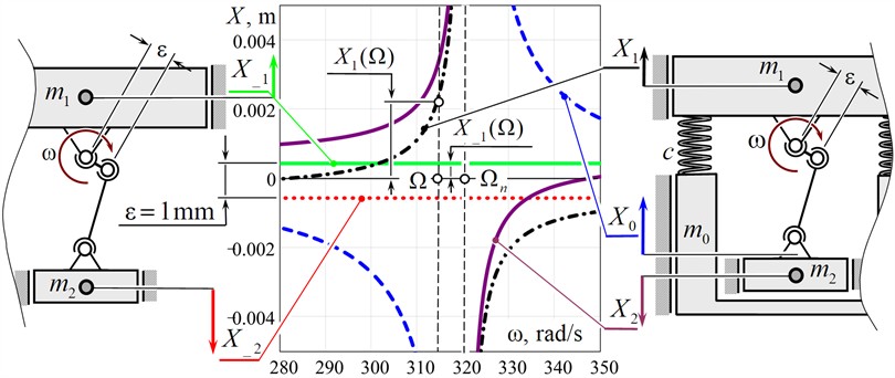
Analyzing the amplitude-frequency characteristics (Fig. 3), it can be seen that at an excitation frequency of 314 rad/s, the amplitude of the oscillations of the active masses of the non-resonant and resonant vibration systems are: 0.44 mm and 2.1 mm, respectively. Thus, the working body of the resonant vibration system exhibits a vibration amplitude 4.8 times higher than that of the non-resonant system. The overload acting on the working body , where is the acceleration due to gravity, is equal to 4.4 and 21 for the non-resonant and resonant systems, respectively. Such an increase in the operating efficiency is achieved by converting the support frame into an oscillating mass.
However, it is necessary to analyze the ratio of the power consumption of the two vibration systems in order to properly assess their operating efficiency. For the vibration system shown in Fig. 1, the drive power consumption is proportional to the expression [13]:
For the vibration system shown in Fig. 2, the drive power consumption is proportional to the expression:
where .
Using the parameters specified above, the following ratio is obtained: 5.5. Thus, the drive power consumption of the resonant vibration system is 5.5 times higher than that of the non-resonant two-mass vibration system. This is because the working body of the resonant vibration system exhibits a significantly larger vibration amplitude than the working body of the non-resonant system. If the vibration amplitudes of the working bodies of both systems are equalized by setting the vibration amplitude of the working body of the resonant vibration system to 0.44 mm (when 0.000212 m), the resonant vibration system will require one-quarter of the drive power required by the non-resonant system. Therefore, when compared under identical operating conditions, i.e., at the same vibration amplitude of the working body, the resonant vibration system demonstrates substantially higher energy efficiency. Consequently, resonant vibration systems remain a more energy-efficient solution.
5. Conclusions
Thus, the approach proposed by the authors makes it possible to increase the operating efficiency of the non-resonant eccentric-pendulum vibration stand (Fig. 1) while requiring only minimal changes to its design. To achieve this, the non-resonant vibration system of the vibration stand was converted into a resonant one (Fig. 2), in which a resonant elastic unit was installed in place of the vibration isolators. In this case, the frame was converted into an oscillating mass. To prevent the transmission of vibrations to the foundation, the frame was placed on vibration isolators. The mass of the entire structure remained practically unchanged, and the operating efficiency of the newly formed vibration system increased significantly. Thus, the working body of the resonant vibration system exhibits a 4.8 higher vibration amplitude than that of the non-resonant system (Fig. 3).
The approach proposed by the authors can be used to increase the operating efficiency of non-resonant vibration systems used in vibration stands or vibration machines, provided that acceptable dynamic operating conditions can be ensured. The mass of the overall structure remains practically unchanged, whereas the operating efficiency of the newly formed vibration systems increases significantly.
References
-
P. Czubak, “Vibratory conveyor of the controlled transport velocity with the possibility of reversal operations,” Journal of Vibroengineering, Vol. 18, No. 6, pp. 3539–3547, 2016, https://doi.org/10.21595/jve.2016.17257
-
R. Modrzewski, A. Obraniak, A. Rylski, and K. Siczek, “A study on the dynamic behavior of a sieve in an industrial sifter,” Applied Sciences, Vol. 12, No. 17, p. 8590, 2022, https://doi.org/10.3390/app12178590
-
S. Ogonowski and P. Krauze, “Trajectory control for vibrating screen with magnetorheological dampers,” Sensors, Vol. 22, No. 11, p. 4225, Jun. 2022, https://doi.org/10.3390/s22114225
-
V. Gursky, P. Krot, V. Korendiy, and R. Zimroz, “Dynamic analysis of an enhanced multi-frequency inertial exciter for industrial vibrating machines,” Machines, Vol. 10, No. 2, p. 130, Feb. 2022, https://doi.org/10.3390/machines10020130
-
N. Yaroshevich, V. Puts, T. Yaroshevich, and O. Herasymchuk, “Slow oscillations in systems with inertial vibration exciters,” Vibroengineering Procedia, Vol. 32, pp. 20–25, 2020, https://doi.org/10.21595/vp.2020.21509
-
V. Gursky, I. Kuzio, P. Krot, and R. Zimroz, “Energy-saving inertial drive for dual-frequency excitation of vibrating machines,” Energies, Vol. 14, No. 1, p. 71, Dec. 2020, https://doi.org/10.3390/en14010071
-
G. Filimonikhin, V. Yatsun, A. Kyrychenko, A. Hrechka, and K. Shcherbyna, “Synthesizing a resonance anti-phase two-mass vibratory machine whose operation is based on the Sommerfeld effect,” Eastern-European Journal of Enterprise Technologies, Vol. 6, No. 7 (108), pp. 42–50, 2020, https://doi.org/10.15587/1729-4061.2020.217628
-
V. Yatsun, G. Filimonikhin, N. Podoprygora, and V. Pirogov, “Studying the excitation of resonance oscillations in a rotor on isotropic supports by a pendulum, a ball, a roller,” Eastern-European Journal of Enterprise Technologies, Vol. 6, No. 7 (102), pp. 32–43, Nov. 2019, https://doi.org/10.15587/1729-4061.2019.182995
-
G. Cieplok and K. Wójcik, “Conditions for self-synchronization of inertial vibrators of vibratory conveyors in general motion,” Journal of Theoretical and Applied Mechanics, Vol. 58, No. 2, pp. 513–524, Apr. 2020, https://doi.org/10.15632/jtam-pl/119023
-
Z. V. Despotovic, A. M. Pavlovic, and D. Ivanic, “Exciting force frequency control of unbalanced vibratory actuators,” in 2019 20th International Symposium on Power Electronics (Ee), pp. 1–6, Oct. 2019, https://doi.org/10.1109/pee.2019.8923574
-
V. Gursky and O. Lanets, “Modernization of high-frequency vibratory table with an electromagnetic drive: theoretical principle and modeling,” Mathematical Models in Engineering, Vol. 1, No. 2, pp. 34–42, 2015, https://doi.org/10.21595/mme.2015.16483
-
I. Kolodiy, O. Lanets, P. Maistruk, I. Derevenko, I. Nazar, and I. Khomych, “Modernization of the electromagnetic vibration stand for testing aviation industry products,” Vibroengineering Procedia, Vol. 59, pp. 21–27, Sep. 2025, https://doi.org/10.21595/vp.2025.25065
-
O. Lanets, Fundamentals of Analysis and Design of Vibratory Machines. (in Ukrainian), Lviv, Ukraine: Lviv Polytechnic Publishing House, 2018.
-
V. Korendiy, O. Lanets, O. Kachur, P. Dmyterko, and R. Kachmar, “Determination of inertia-stiffness parameters and motion modelling of three-mass vibratory system with crank excitation mechanism,” Vibroengineering Procedia, Vol. 36, pp. 7–12, Mar., https://doi.org/10.21595/vp.2021.21924
-
V. Korendiy, O. Yaniv, R. Predko, I. Laushnyk, A. Dzyubyk, and S. Hrevtsov, “Trajectory-based synthesis of a three-mass vibratory system excited by a dual phase-controlled crank-slider mechanism,” Vibroengineering Procedia, Vol. 62, pp. 41–50, Jun. 2026, https://doi.org/10.21595/vp.2026.261652021
-
T. Svyshch, O. Lanets, P. Maistruk, I. Derevenko, I. Nazar, and I. Khomych, “Modeling the operation of an eccentric-pendulum resonant vibration stand for testing aviation industry products,” Vibroengineering Procedia, Vol. 59, pp. 34–40, Sep. 2025, https://doi.org/10.21595/vp.2025.25064
About this article

The authors have not disclosed any funding.
The datasets generated during and/or analyzed during the current study are available from the corresponding author on reasonable request.
Prof. Oleksii Lanets is a scientific committee member of the 78th International Conference on Vibroengineering and was not involved in the editorial review and/or the decision to publish this article.

