Abstract
The two dimensional system of pipes is investigated. The model of a pipe system consisting from two dimensional beams by taking the inertia of fluid filling the pipes into account is used and the eigenmodes are determined. The places of the pipe with small amplitudes of vibrations and with large amplitudes of vibrations for the eigenmodes are determined. Then the places where the amplitudes for several first eigenmodes are large are determined. In those places it is recommended to perform measurements of vibrations of the pipe system.
1. Introduction
The two dimensional system of pipes is investigated. The model of a pipe system consisting from two dimensional beams by taking the inertia of fluid filling the pipes into account is used and the eigenmodes are determined.
The places of the pipe with small amplitudes of vibrations and with large amplitudes of vibrations for the eigenmodes are determined. Then the places where the amplitudes for several first eigenmodes are large are determined. In those places it is recommended to perform measurements of vibrations of the pipe system.
The model for the analysis of vibrations of a pipe system is proposed on the basis of the results described in [1, 2, 3].
2. Model for the analysis of vibrations of a pipe system
In the description of the model of the pipe presented below , and denote the axes of the system of coordinates. The finite element of a two dimensional beam representing the pipe in the plane has three nodal degrees of freedom: the displacement in the direction of the axis denoted as , the displacement in the direction of the axis denoted as and the rotation about the y axis denoted as .
The values of , , in the element of a pipe are represented as:
where is the vector of generalized nodal displacements and:
where are the shape functions of the one dimensional finite element of the pipe.
The displacements in the direction of the longitudinal axis of the pipe s and in the direction of the axis perpendicular to s and located in the plane are denoted as and . They are related with the displacements in the global directions as:
where:
where is the local coordinate of the finite element of the pipe and:
The following notation is used:
The derivatives of , , are assumed as:
where:
On the basis of the previous notations it is assumed that:
The following notation is used:
The stiffness matrix of the model of a pipe has the form:
where is the modulus of elasticity of the pipe, is the Poisson’s ratio of the pipe, is the internal radius of the pipe, is the external radius of the pipe and:
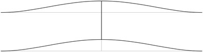
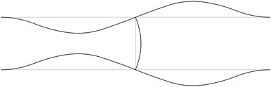
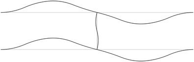
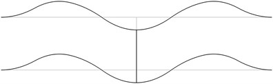
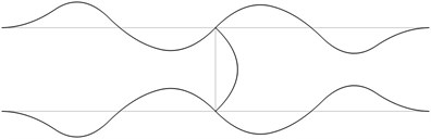
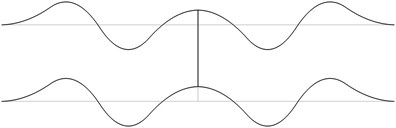
Fig. 1The first eigenmodes of the pipe system: a) the first eigenmode, b) the second eigenmode, …, j) the tenth eigenmode
a)
b)
c)
d)
e)
f)
g)
h)
i)
j)
The mass matrix of the model of a pipe has the form:
where is the density of the material of the pipe, is the density of the fluid filling the pipe.
3. Results of analysis of vibrations of a pipe system
The structure consists from a lower straight pipe and an upper straight pipe both of them having fixed ends (all of the generalized displacements equal to zero) and they are assumed filled with water. The midpoints of both pipes are connected by an empty pipe perpendicular to them. Length of the structure is 2 m and the distance between the lower and upper pipes is 0.4 m. The following parameters are assumed: modulus of elasticity of the pipes 6·108 Pa, Poisson’s ratio of the pipes 0.3, density of the material of the pipes 785 kg/m3, density of the fluid filling the two pipes 998 kg/m3, internal radius of the pipes 0.004 m, external radius of the pipes 0.006 m. The first eigenmodes are presented in Fig. 1.
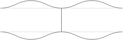
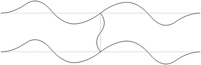
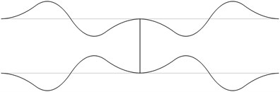
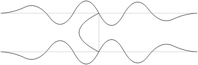
Fig. 2The acceptable places of measurement for the first eigenmodes of the pipe system: a) for the first eigenmode, b) for the second eigenmode, …, j) for the tenth eigenmode

a)

b)

c)

d)

e)

f)

g)

h)

i)

j)
4. Measurement of vibrations of a pipe system
In order to perform precise measurements of vibrations of a pipe system the measurements are to be performed not at the nodes of the eigenmodes and preferably at the places with higher amplitudes of vibrations. It is considered that the amplitudes are large when they are greater than half of the maximum amplitude of vibrations for the eigenmode. The places with small amplitudes are denoted by black lines and the places with large amplitudes are denoted by grey lines. The acceptable places of measurement for the first eigenmodes are presented in Fig. 2.
The obtained acceptable places for measurements for the first five eigenmodes are presented in Fig. 3. Thus when it is necessary to perform measurements of vibrations in the frequency range which includes the eigenfrequencies of the first five eigenmodes the device for measurement of vibrations must be located at the places of the pipes denoted by grey lines in this figure.
Fig. 3The acceptable places of measurement for the first five eigenmodes of the pipe system

5. Conclusions
The structure consisting from a lower straight pipe and an upper straight pipe both of them having fixed ends (all of the generalized displacements equal to zero) and filled with water is investigated. The midpoints of both pipes are connected by an empty pipe perpendicular to them. The first eigenmodes are obtained.
In order to perform precise measurements of vibrations of a pipe system the measurements are to be performed not at the nodes of the eigenmodes and preferably at the places with higher amplitudes of vibrations. It is considered that the amplitudes are large when they are greater than half of the maximum amplitude of vibrations for the eigenmode. The acceptable places of measurement for the first eigenmodes are determined.
Thus the acceptable places for measurements for the first several eigenmodes are easily obtained by using this approach.
References
-
Bathe K. J. Finite Element Procedures in Engineering Analysis. New Jersey, Prentice-Hall, 1982.
-
Zienkiewicz O. C. The Finite Element Method in Engineering Science. Moscow, Mir, 1975.
-
Bolotin V. V. Vibrations in Engineering. Handbook, Vol. 1, Moscow, Mashinostroienie, 1978.
About this article

