Abstract
A new finite element model is developed to perform vibration analysis of a cracked pipe. To formulate the method, the local flexibility coefficients of a part-through circumferential crack in a pipe that is subjected to axial force, shear force and bending moment are analytically derived using linear fracture mechanics. In particular, an adaptive Simpson method is utilized to carry out the numerical integration for calculating the flexibility coefficients. With the flexibility coefficients, a finite element model is established to study the vibration characteristics of the cracked pipe, with particular emphasis on the crack effect represented by change in natural frequency. As an illustrative application, the finite element model is utilized to identify a crack in a pipe by contour plots of frequency ratio as function of crack location and crack depth, with the crack location and depth identified accurately. The proposed method is effective in characterizing the vibration behavior of a pipe with a crack.
1. Introduction
The pipe is a vehicle for liquid transportation in various industrial sectors such as civil engineering, offshore engineering, transportation infrastructure, military facilities, and port structures, and is especially widely used in power plants, chemical plants, and gas and oil transportation. Owing to material aging, corrosion and environmental influence, damage inevitably occurs in some part of an in-service pipe. In particular, a part-through circumferential crack is the prevailing type of damage in a pipe. Such a crack may impair the pipe’s performance, reducing its capacity to resist disaster. Vibration is a key factor that originates crack in a pipe; moreover, vibration can also expedite extension of the crack. Vibration analysis of a pipe with a crack is essential, therefore, for detecting cracks [1, 2], evaluating the performance, and predicting the residual life. Unfortunately, development of valid method to conduct vibration analysis for a cracked pipe is still a poorly resolved scientific issue. To resolve this issue, the key is to calculate the local flexibility coefficient induced by a part-through circumferential crack.
A crack in a structure induces stress concentration area at the crack tip, and this stress concentration can variation in the local flexibility of the structure. Irwin [3] presented the concept of local flexibility and the relationship between crack tip stress concentration and quantitative load. Dimarogonas used a massless rotational spring to model a crack and simulate its vibration behavior [4], with the equivalent stiffness spring established based on the principle of fracture mechanics. Papadopoulos and Dimarogonas [5-7] established an approach to calculate a complete 6×6 local flexibility matrix. Their method was appropriate for modeling a crack not only for Euler Bernoulli beams, but also for a Timoshenko beams with arbitrary load conditions. That crack model based on local flexibility has been widely applied to vibration analysis and crack identification in structures.
In contrast to the numerous studies of cracking in beams, studies of cracking problems in pipes based on local flexibility are relatively lacking [8-11]. Liu et al. [8] investigated crack detection in a circumferentially cracked pipe using coupled response measurements. The cracked segment was represented by a local flexibility matrix connecting two undamaged beam segments. Naniwadekar et al. [9] proposed an approach to crack identification based on change characteristics of natural frequencies, adopting a rotational spring to simulate crack behavior in straight steel hollow pipe. An effective tool for analysis of vibration and stability of a cracked pipe was presented by Zheng et al. [10], based on local flexibility by virtue of theory of linear fracture mechanics. The local flexibilities of both shallow and deep penetration cracks were respectively deduced by taking shear force into account, and the corresponding values were obtained by the least-squares method. Further, the local flexibility equations of a cracked pipe subjected to a combination with axial force, shear force and bending moment were derived by Hu et al. [11]. Adaptive Quadrature-Revisited (AQR) was used to perform the numerical integration to obtain the local flexibility coefficients.
To accurately characterize crack-induced local flexibility in a pipe, this study formulates the local flexibility equations related to a part-through circumferential crack based on the theory of linear fracture mechanics. The proposed equations involving axial force, shear force and bending moment, are calculated by adaptive Simpson numerical integration. On the basis of the proposed local flexibility coefficients, a finite element model for a cracked pipe is established. This model provides an effective method of characterizing the vibration behavior of a pipe with a crack. As an illustrative application, the finite element model is used to detect a crack in a pipe, with location and crack depth identified accurately.
2. Local flexibility equations
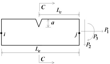
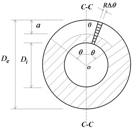
A pipe element with a part-through circumferential crack is shown in Fig. 1(a); the crack is detailed in Fig. 1(b), where is the crack depth in circumferential direction, the crack angle, the pipe thickness, and the outer diameter and the inner diameter of the pipe, respectively. The direction of axial force is chosen to be the same as that of the axial line of the pipe. The directions of shear force and bending are shown in Fig. 1(a).
The crack section of a part-through circumferential crack is a circular area, and it is not possible to directly acquire the correlative stress intensity factor to calculate the local flexibility coefficient. To this end, the principle proposed by Dimarogonas [4] for building local flexibility of a cracked rotor is used as reference. The circular crack area is divided into a sequence of discrete approximation trapezoidal strips, as shown in Fig. 1(b). For each strip, the additional strain energy attributable to the crack can be calculated by planar beam theory, and then the total strain energy is obtained by totaling all additional strain energy.
The local flexibility can be calculated using linear fracture mechanics and the stress energy release principle. It is assumed that the cracking behavior is in the scope of linear elasticity fracture mechanics. From the theory of linear elastic fracture mechanics, the additional strain energy due to crack can be expressed as [4]:
where is the strain energy release rate function and is the effective cracked area. The strain energy release rate function can be formulated as:
where , and are the stress intensity factors with Model I under loads , and , respectively; is the stress intensity factor with Mode II under shear force. For a plane stress problem, ; and for a plane strain problem, , where is the elastic modulus and is the Poisson ratio.
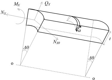
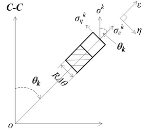
Fig. 1a) Cracked pipe element; b) part- through circumferential crack section; c) strip of crack section; d) stress decomposition of strip
a)
b)
c)
d)
Additional displacement introduced by crack can be expressed as:
where ( 1, 2, 3) are axial force, shear force and bending moment, respectively. Therefore, the local flexibility coefficient introduced by the crack can be expressed as:
where (, 1, 2, 3) is the local flexibility coefficient for cracked pipe subjected to different loads.
The crack section of the part-through circumferential crack (Fig. 1(b)) can be equally divided into small units, leading to the crack angle of each unit being (Fig. 1(c)). When the width of each unit is sufficiently small, the cross-section of the unit can be regarded as a trapezoidal section. For convenience of the integration to calculate the additional strain energy of each unit, the trapezoidal cross-section can be approximately regarded as a rectangle whose width is , where .
The additional strain energy attributable to each crack unit can be expressed as:
where is the additional strain energy of th crack unit, the stress energy release ratio of the th crack unit, and and the ordinate and abscissa which measure the crack depth and the deviation of the crack strip, respectively.
For the th crack unit, the stress component in the direction of the C-C axis is displayed in Fig. 1(d). The stress intensity factor of the th crack unit in the directions of the axial force, shear and bending moment can be expressed as [12]:
where ; is the angle between the centerline and the C-C axis; , and are the correction parameters of stress intensity factor due to the crack:
where , , .
Substituting Eqs. (6)-(9) into Eq. (5), the stress energy of the th crack unit can be calculated by the following expression:
The total additional stress energy of the cracked pipe can be expressed by:
Assuming that the width of the crack unit is infinitesimal, the total additional stress energy of the cracked pipe can be expressed in the integral format:
With Eqs. (14), (15), the local flexibility coefficients of a part-through circumferential crack can be expressed as follows:
where , , the dimensionless local flexibility coefficients of the cracked pipe with a part-through circumferential crack can also be obtained as:
The dimensional local flexibility coefficient is a double integral function about the functions of and , and its integral function can be very complex. It is not possible, therefore, to calculate the dimensionless local flexibility coefficient by direct integration of the analytic expression. To obtain a more accurate local flexibility coefficient, an adaptive Simpson numerical integration procedure is developed. The adaptive Simpson algorithm [13] features advantages such as fast efficiency and high precision, among others.
On the basis of the above discussion, the local flexibility due to the crack is expressed as:
3. Finite element model for vibration analysis
3.1. Finite element model
For a cracked pipe element, like that shown in Fig. 1(a), its total flexibility can be represented by the sum of the flexibility of the corresponding intact pipe element and that of the crack. The intact pipe element can be modeled using Euler-beam elements with two nodes each having three degrees of freedom, i.e., longitudinal displacement, vertical displacement, and rotation. The flexibility of the intact pipe element is:
where is the length of the element, and and are the second moment of inertia and sectional area, respectively. The flexibility of the crack is given in Eq. (28). In combination, the total flexibility of a cracked pipe element is specified by:
where is the total flexibility of the cracked element.
As per the principle of the virtual work, the stiffness matrix of the cracked element can be written as:
where the transfer matrix is expressed as:
The characteristic equation of free vibration of the cracked pipe, without consideration of damp, can be written as:
where and are total stiffness matrix and mass matrix respectively of the cracked pipe, and are corresponding natural frequency and mode shape, respectively. is formed by assembling for the cracked element and for the undamaged element, with defined in Eq. (31) and given as:
where:
is the mass density per unit length. is the form of consistent mass matrix for a pipe element regardless the existence of a crack:
3.2. Vibration characteristics analysis
The proposed finite element model is utilized to analyze the vibration characteristics of a cracked pipe (Fig. 2), with the material and geometric parameters listed in Table 1. The crack angle of a part-through circumferential crack is . A metric of change ratio of natural frequency is defined to quantify the crack effect by:
where and (1, 2, 3) are the natural frequencies of the cracked and intact pipes, respectively.
Fig. 2A cantilever pipe with a crack
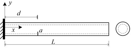
Table 1Material and geometric properties of the pipe (Fig. 2)
External diameter | Internal diameter | Length | Elasticity modulus | Poisson’s ratio |
42 mm | 30 mm | 765 mm | 203 GPa | 0.27 |
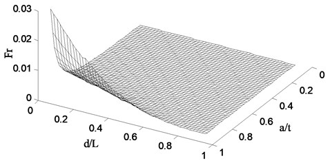
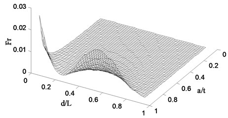
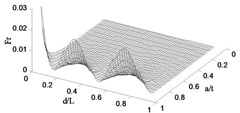
Following the procedure described in Section 3, the finite element model is created to simulate the pipe with a crack defined by two parameters: relative crack location with d being the distance of the crack from the fixed end, and relative crack depth varying with t being the thickness of the pipe. For a specific crack scenario, the change ratio of natural frequency can be obtained by the vibration analysis using the finite element model. When a series of crack cases, specified with ranging from 0 to 1 and from 0 to 0.3, a set of change ratio of natural frequency can be obtained for a certain order natural frequency, which constitutes a damage spectrum. The damage spectra for the first three natural frequencies are shown in Figs. 3(a), 3(b), and 3(c), respectively. The damage spectra depict the effect of crack on the vibrational properties of the pipe. Fig. 3(a) shows that the Fr of the first natural frequency monotonically decreases with the crack location varying from the fixed end to free end, implying gradually weakened crack effect. Figs. 3(b) and 3(c) present that there is no such a monotonic relation between and crack location, indicating is a non-monotonic function of crack location. Moreover, in the case of the same crack location, the deeper the crack causes larger as well as more decreases in natural frequency.
Fig. 3Damage spectra for the a) 1st, b) 2nd, and c) 3rd natural frequencies
a)
b)
c)
4. Illustrative application: crack identification
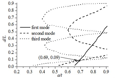
Application of the finite element model is illustrated in the case of identifying a part-through circumferential crack in the pipe (Fig. 2). The crack is specified by the parameters: 0.09, 0.7, and 0.5. The natural frequency contour map (NFCM) method [15, 16] is selected to identify the crack. This method can identify both crack location and depth simultaneously, distinct from the frequency-change-ratio method [14] and optimization-based frequency method [17, 18]. The NFCM method estimates the location and extent of a crack using natural frequencies, incorporating the finite element model of the pipe. The frequency contours of crack depth versus crack location are plotted for the first three natural frequencies and the intersection points of the contours graphically indicate the location and depth of the crack being inspected.
To identify the crack, three frequency contours for the 1st, 2nd, and 3rd-order natural frequencies are obtained using the finite element method, as shown in Fig. 4. In this figure, it can found that these three frequency contours intersect at the point: 0.09, 0.69, offering the estimated crack location and crack depth. This identification result is in good agreement with the actual damage state with the related error less than 1 %.
Fig. 4Contour map for a cracked cantilever pipe
5. Conclusions
This study derives the local flexibility coefficients of a part-through circumferential crack in a cantilever pipe relying on linear fracture mechanics theory. The proposed local flexibility coefficients contain the contribution from axial force, shear force and bending moment. With the derived local flexibility coefficients, a finite element model is formulated for conducting vibration characteristics analysis of the cracked pipe. Using the finite element model, the effect of the crack on the vibration properties of the cracked pipe is investigated. Moreover, an illustrative application of the finite element model to crack identification in a pipe with a part-through circumferential crack is provided, indicating the usefulness of the method.
References
-
Cao M. S., Radzieński M., Xu W., Ostachowicz W. Identification of multiple damage in beams based on robust curvature mode shapes. Mechanical Systems and Signal Processing, Vol. 46, Issues 2-3, 2014, p. 468-480.
-
Cao M., Xu W., Ostachowicz W., Su Z. Damage identification for beams in noisy conditions based on Teager energy operator-wavelet transform modal curvature. Journal of Sound and Vibration, Vol. 333, Issue 6, 2014, p. 1543-1553.
-
Irwin G. R. Analysis of stresses and strains near the end of a crack traversing a plate. Journal of Applied Mechanics, Vol. 24, 1957, p. 361-364.
-
Dimarogonas A. D. Analytical Methods in Rotor Dynamics. Applied Science Publishers, Essex, 1983.
-
Papadopoulo C. A. Some comments on the calculation of the local flexibility of cracked shafts. Journal of Sound and Vibration. Vol. 278, Issues 4-5, 2004, p. 1205-1211.
-
Papadopoulos C. A. The strain energy release approach for modeling cracks in rotors: a state of the art review. Mechanical Systems and Signal Processing, Vol. 22, Issue 4, 2008, p. 763-789.
-
Dimarogonas A. D. Vibration of cracked structure: a state of the art review. Engineering Fracture Mechanics, Vol. 55, Issue 5, 1996, p. 831-857.
-
Liu D., Gurgenci H., Veidt M. Crack detection in hollow section structures through the coupled response measurements. Journal of Sound and Vibration, Vol. 261, Issue 1, 2003, p. 17-29.
-
Naniwadekar M. R., Naik S. S., Maiti S. K. On predection of crack in different orientations in pipe using frequency based approach. Mechanical Systems and Signal Processing, Vol. 22, Issue 3, 2008, p. 693-708.
-
Zheng D. Y., Fan S. Vibration and stability of cracked hollow-sectional beams. Journal of Sound and Vibration, Vol. 267, Issue 4, 2003, p. 933-954.
-
Hu J. S., Sun W. Y. Free vibration analysis of pipe with a part-through crack. The 3rd World Conference on Safety of Oil and Gas Industry, 2010, p. 302-308.
-
Zheng D. Y., Kessissoglou N. J. Free vibration analysis of a cracked beam by finite element method. Journal of Sound and Vibration, Vol. 273, Issue 3, 2004, p. 457-475.
-
Gander W., Gautschi W. Adaptive quadrature-revisited. BIT, Vol. 40, 2000, p. 84-101.
-
Cawley P., Adams R. The locations of defects in structures from measurements of natural frequencies. Journal of Strain Analysis, Vol. 14, Issue 2, 1979, p. 49-57.
-
Nikolakopoulos P. G., Katsareas D. E., Papadopoulos C. A. Crack identification in frame structures. Computers and Structures, Vol. 64, Issues 1-4, 1997, p. 389-406.
-
Cao M. S., Song X. G., Xu W., et al. Performance of assessment of natural frequencies in characterizing cracks in beams. Journal of Vibroengineering, Vol. 16, Issue 2, 2014, p. 1010-1021.
-
Suh M. W., Shim M. B., Kim M. Y. Crack identification using hybrid neuro-genetic technique. Journal of Sound and Vibration. Vol. 238, Issue 4, 2000, p. 617-635.
-
Qian X. D., Cao M. S., Su Z. Q. A hybrid particle swarm optimization (PSO)-simplex algorithm for damage identification of delaminated beams. Mathematical Problems in Engineering, Vol. 2012, 2012, p. 607418.
Cited by
About this article

