Abstract
Pipe flow is designed to avoid sea foam formation at a power plant outfall at Angamos, Chile, instead of present open channel. A flap gate is designed at the end of the pipe to control variable high pressure caused by large head difference between sea level and ground level of the power plant constructed by POSCO in 2003. Present open channel is 14 m long over sloped ground from the plant. The foam is formed by air entrainment from free surface with high disturbance. Flap gate counter-weight is a function of the flap gate gap, and should be well chosen to have adequate opening water head, and allow both normal and emergency-operational flow fluxes. Natural oscillation frequency of the flap gate due to interaction with water pressure and frequency of fluid eddy shedding should not amplify unexpected motion. Laboratory experiments were carried out to find out optimal shape and weight of flap gate for this pipe flow. Long pipeline was represented as a vertical column considering experimental space. Selected counter-weight shows reasonable gap under high pressures, and no unwanted vibration was observed.
1. Introduction
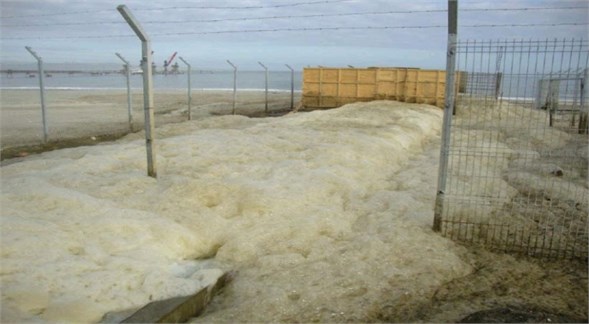
The outfall of a power plant at Angamos, Chile, constructed by POSCO in 2003 in Fig. 1 has an open channel over sloped ground from the plant exit to the sea, see Fig. 2. The ground level of the channel beginning is about 15 m higher than the mean sea level. The outfall discharge at normal and emergency operations are 1.2 and 2.7 m3/s, respectively. When the discharged water enters the sea, significant amount of foam is formed, lasts for long time, and spreads over nearby coastline, see Fig. 3.
Fig. 1Angamos power plant, Chile
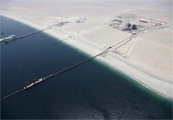
Fig. 2Original open channel outfall at Angamos power plant
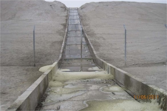
Fig. 3Foam generated from outfall spreads over nearby coast (Angamos, Chile)
Residents near the plant have claimed countermeasure or compensation for environmental damage, e.g. odour, spoiled scenery, effect on fishing, and surfing. Most sea foam is not directly harmful to humans. But when large algal blooms decay near shore, there is potential for impacts to human health and environment. For example, sometimes algal toxins become airborne, and the resulting aerosol can irritate people’s eyes at beach, and can pose health risk for those with respiratory disorders. Bird scientists found that sea foam removes waterproofing of bird feathers, and makes bird have difficulty in flying.
Some other coasts have suffered similar problems. Outfall of Boryeong Thermal Power Plant, Korea caused foam formation, and a treatment is tried at the moment [1]. Sunshine Coast in 2013, Aberdeen in 2012, Cleveleys, Lancashire in 2011, Maryland, Tucker Barnes in 2011 was covered in sea foam, influenced by high wind and waves as external forces. Especially wave breaking provide air entrainment and disturbance at the same time. Each coastal region has different conditions related to formation of sea foam. In general sea foam is better formed if air is entrained in sea water at unstill free surface, and the formed sea foam lasts for long time if sea water is contaminated biologically or chemically.
Biological or chemical details of formation and endurance of sea foam at Angamos Power Plant has not well been analyzed yet. Free surface is disturbed by high turbulence along open channel with supercritical flow, and by the jet flow at the seal pit at the end of the channel.
Methods have been developed to suppress foam formation or break formed sea foam in a few directions, i. e. mechanical or vibrational way [2-3], chemical way, and hydraulic way [1]. Several commercial defoamers or anti-foam agents are manufactured [4]. Both mechanical and chemical methods have demerits, i.e. expensive, require continuous maintenance cost, and more seriously may cause secondary environmental contamination problems. Hydraulic method would be ideal, if there is, because it does not require high maintenance cost, solves the problem from base, and does not cause any further pollution problem [5-6]. A hydraulic solution adopting pipe flow to Angamos Power Plant is proposed here as a countermeasure to the present open channel outfall.
2. Laboratory experiment for selection of flap gate counter-weight
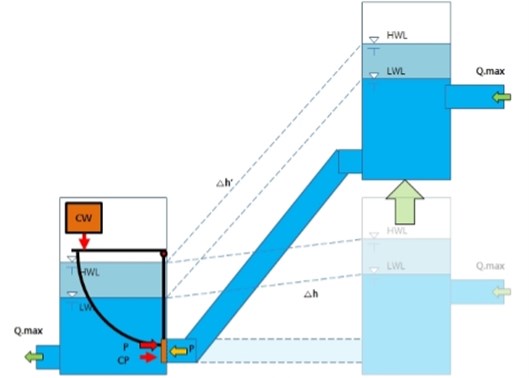
The present waterway to carry plant cooling water discharge from the plant to the sea is an open channel. Its average slope is of 1/4, which is steep enough to make the water flow supercritical. While water flows down the channel, air is easily entrained in water, and huge amount of sea foam is formed in this open channel. To reduce free surface area along the channel, a pipe channel is designed here to replace the present open channel. Then the bottom end of the pipe is subject to high pressure due to large head difference between the top and the bottom of the pipe. Discharge at normal operation at the outfall is 1.2 m3/s, and enhanced discharge for emergency operation is 2.7 m3/s. The seal pit is separated from the inlet channel by a flap gate. A flap gate is selected to allow both normal and emergency discharges at the bottom of the pipe, which doesn’t need manual operation for discharge variation. The hinge of the flap gate is situated above the gate linked by frame, and an adjustable counter-weight is put on the frame. This arrangement helps the gate open almost in parallel so that water flows through gap along the circular perimeter of the gate. The gate has a hat to protect jet flow through upside gap between the gate and the pipe end towards free surface.
The opening between the pipe end and the flap gate depends on the weight size and inflow water head. The gate should open at opening condition, and should adopt discharges for normal and emergency operations. There is a limit on gate gap so that the gate can control flow rate.
In order to find the optimum counter-weight of the gate hydraulic model tests were carried out by using a two-dimensional flume at Kookmin University, Korea. Scale of 1/14 was selected considering flume size. Test cases include discharges for normal and emergency operations, and sudden transitions between two discharges.
Fig. 4Laboratory experimental setup for testing flap gate
Acting gate gap should not exceed certain length; the gap reacts almost linearly against excess net force (total force minus opening force) while it is small. Ideal gap for normal operation should be less than around 1/10 of the gate diameter. The gap for emergency operation is larger than that for normal case, and doesn’t need additional caution. By repeating several weight sizes, proper weight size of 1200 kg was chosen.
Table 1Backwater level versus flap gate gap
Discharge | Gap (cm) | Upstream water head (m) |
Normal Operation ( 0.1 m3/s) | 0.2 | 0.235 |
Emergency Operation ( 0.225 m3/s) | – | 0.383 |
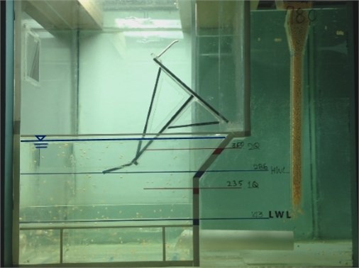
Results show that the above gap widths are acceptable in general. Flow through the gap between the upside gate hat and the pipe end was not strong to agitate free surface above it for both discharges, see Figs. 5, 6.
Fig. 5Detailed flow snapshot for steady inflow (Q= 0.1 m3/s)
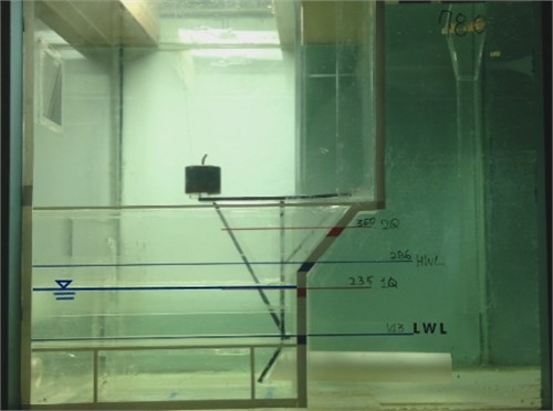
Fig. 6Operation of flap gate for sudden change of inflow flux (Q= 0.225 m3/s)
Danger of natural oscillation should be checked for rotatable flap gate. Natural oscillation frequency of external force-swing response mechanism, and eddy shedding frequency of the flow had better not coincide or have small integer multiple. First, oscillation of the flap gate due to pressure variation of surrounding flow is a possible oscillation mode during operation. The gate motion due to external force can be expressed as a spring system [7-8]. The spring characteristics are related to the gate weight and hydrodynamic pressure deviation from mean value. Second, flow vortex shedding frequency around the gate can initiate gate oscillation. If ambient flow is uniform, the vortex shedding frequency can be estimated from an empirical equation involving Strouhal number and Reynolds number as:
where is the vortex shedding frequency, is the diameter of the gate, and is the flow velocity passing by the gate [9]. The above formula generally holds true for between 250 and 2×10⁵. However, the flow around the gate is not uniform, and the above equation cannot give accurate answer for complicated case like this. In order to check the oscillation amplification problem, small artificial impact of artificial displacement of the gate was applied to the model flap gate while flow was steady. The result revealed that artificial impacts decayed so quickly that it was meaningless to measure the frequency of its response, which is satisfactory. Experimental results for both normal and emergency discharge cases, and sudden discharge change cases between the two discharges were both ok.
3. Conclusions
A counter-measure of serious foam formation at Angamos Power Plant, Chile is designed, and verified with hydraulic modelling. New system involves pipe channel and a flap gate. Adequate counter-weight of the flap gate was chosen from hydraulic model test. Oscillation amplification danger was checked at the experiment, and the result is satisfactory for the chosen counter-weight. It is believed that the new system may be very effective to suppress foam generation, because flow is not much exposed to the air throughout the waterway. Future numerical modelling may be meaningful to look in detailed flow feature around the gate.
References
-
Oh S. H., Oh Y. M., Kang K. S., Kim J. Y. Experimental investigation on the efficiency of reducing air bubble formation by installing horizontal porous plate in the submerged outlet structure of power plant. Journal of Korean Society of Coastal and Ocean Engineers, Vol. 20, 2008, p. 472-481, (in Korean).
-
Barigou M. Foam rupture by mechanical and vibrational methods. Chemical Engineering Technology, Vol. 24, 2001, p. 659-663.
-
Goldberg M., Rubin E. Mechanical foam breaking. I&C Process Design and Development, Vol. 6, 1967, p. 195-200.
-
Garret P. R. Defoaming Theory and Industrial Applications: Surfactant Science Series v.45. Marcel Dekker Inc., New York, 1993.
-
Burt C. M., Angold R., Lehmkuhl M., Styles S. Flap gate design for automatic upstream canal water level control. Journal of Construction Engineering and Management, Vol. 127, 2001, p. 84-91.
-
Litrico X., Belaud G., Baume J-P., Ribot-Bruno J. Hydraulic modeling of an automatic upstream water-level control gate. Journal of Irrigation and Drainage Engineering, Vol. 131, 2005, p. 176-189.
-
Khaledi H. A., Andersson H. I., Barri M. Flow past a normal flat plate undergoing inline oscillations Physics of Fluids, Vol. 24, 2012, p. 093603-1-33.
-
Yang Y., Thomas W., Strganac T. W. Experiments of vortex-induced torsional oscillation of a flat plate in cross flow. AIAA Journal, Vol. 51, 2013, p. 1522-1526.
-
White F. M. Fluid Mechanics. McGraw Hill, India, 2011.
About this article

This work has been supported by POSCO E&C, and KIMST as a research project MIDAS (Development of Coastal Erosion Control Technology) 2014.
