Abstract
The analysis of parts’ placement and orientation influence during punching process on the treated pieces quality was performed by analyzing practically the parts’ – fixing element’s layout, cutting, and bending processes. The possibilities to improve the performance of punching process and treated pieces quality by analysis of tools vibrations influence were theoretically performed there too.
1. Introduction
The present automobile, electrical, furniture, and other manufacturing companies use punching processes for producing parts from metal, as punching usually is the cheapest method for creating various details from metal sheet in medium and high production.
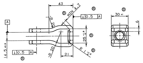
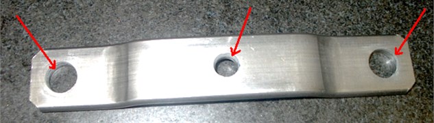
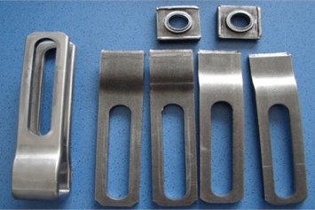
The analysis for finding parts placement influence during punching process was carried out in order to obtain the data about errors by analyzing practically the parts’ – fixing element’s layout (Fig. 1), cutting, and bending processes. The possibilities to avoid them were analyzed there too. Also all the accuracy requirements for it have to be kept according as shown in Fig. 2.
The application of ultrasonic vibrations on punch or die can improve the quality of edge profile and stabilize the punching process itself.
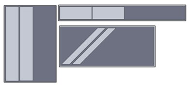
Fig. 1Fixing element
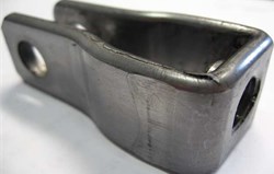
Fig. 2Drawing of fixing element
2. Part outline creating process
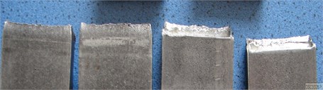
The outline for given detail will be just simple metal strip as shown in Fig. 3.
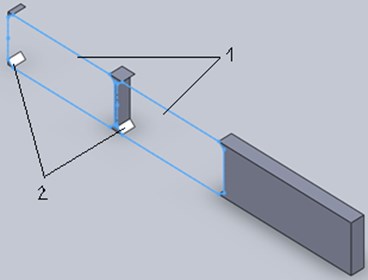
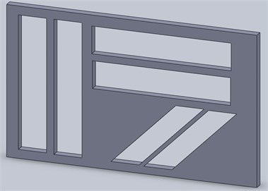
Part sheet outline is the starting point for the stamp construction, and it is created by graphical programs (Fig. 4). Technical designer has many possibilities to try several different ways until the optimal conception of part sheet outline by using software will be found. It helps to decrease the losses of material by close as possible development of the part sheet outline and the stamp. The parts are arranged on the possible sketch where part sheet outlines are possibly near each other on metal sheet [1].
The optimum utilization of material is reached, if the part outline is of the same width or length as used metal sheet, i.e. can be cut from the material without waste. The disadvantages of this cutting are that the burr is not only on a side of the part, but the cutting tools also have complicated forms. The part outlines can be arranged so that the remaining waste should be used for manufacturing of others parts, if optimal usage of material cannot be reached [2].
Fig. 3Outline of fixing elements
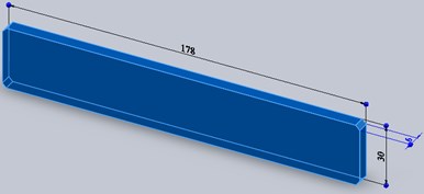
Fig. 4Arrangement of the part outlines in the metal strip: 1 – detail, 2 – waste of material
The material utilization coefficient is the next main factor. Parts which are cut in large numbers from expensive materials have to have the minimal edge roundness on outer surface. Also an optimal strip organization has to be made; that will be done with as much as possible cuts with a little waste.
Fig. 5Stamp arrangement: a) on different metal sheet, b) on single metal sheet
a)
b)
The utilization coefficient is done by comparing the surface of metal sheets with the surface of all of the made parts from it. Figure 5 shows best solutions for stamp arrangement.
The optimal arrangement of analyzed part on the material allows to increase the utilization coefficient approximately by 30 %.
In practice designing the layout of new details part outline will always be made the notice where the part will be used and what form will be needed. For these reasons not only the minimization of the material utilization is taken into account, but also for the choice, what tools will be designed whether plate cutting tool and separate material – deforming tool or whether subsequent group – tool [3].
3. Cutting (punching) process
Punches in the conventional sense are used for a cutting process along a cut line closed in itself for the production of an interior form at the treated piece.
The burr is formed during the holes cutting process when punching at the stamp pulling out side. No general statement can be made over the strength of the formation of a shoulder. It can be different depending upon material and punching. Absolutely burr-free perforated plates could be obtained only by a subsequent treatment. The Fig. 6 shows the burr formation zones.
Fig. 6The burr formations zones
Burrs can be cleaned by brushes, files, loops, milling, glass finish, thermal deburring (e.g. Thermal explosion Machining, TEM), electro-chemical deburring, high-pressure water jet deburring, pressure flowing (DFL) or cuts. There is also the possibility of dipping the treated piece into corrosive or corrosive liquids or of heating it up, in order to defuse the edges.
The quality of cut edge profile is affected not only by ductile fracture process between the punch and die but also by the treated piece material mechanical properties. During punching process was observed that these parameters also depend of the punch load.
Ultrasonic vibrations can be applied in order to improve the quality of cut edge profile and to decrease the punch load [4]. For this process the vibration can be applied to the punch or to the table. Figure 7 shows experiment setup for investigation of these phenomena. The vibration apparatus includes an ultrasonic generator, operating at a frequency of 15 kHz, a piezoelectric force transducer, a tapered horn resonator and a frame [5].
Fig. 7Experiment setup for deep drawing test with high frequency vibration: 1 – frame pillar. 2 – vibration transducer, 3 – support plate, 4 – punch, 5 – tapered horn resonator, 6 – guiding board, 7 – screw and pin, 8 – cushion block, 9 – specimen, 10 – die [5]
![Experiment setup for deep drawing test with high frequency vibration: 1 – frame pillar. 2 – vibration transducer, 3 – support plate, 4 – punch, 5 – tapered horn resonator, 6 – guiding board, 7 – screw and pin, 8 – cushion block, 9 – specimen, 10 – die [5]](https://static-01.extrica.com/articles/14501/14501-img8.jpg)
Vibrations applied to the punch improve the cut edge surface. It also decreases the reduction in friction between tool and the treated pieces thus reducing punch load and energy consumption [5].
Another research was carried out in order to reduce the force acting the punching and cutting tools by using tools vibrations during processing material. These studies were limited by dividing operations, in particular the process of punching and cutting. The research was carried out on press machine model A6432A with nominal force 160 t, by using plate of steel 3 GOST19903-74. The plate’s thickness was 3.9 mm and, cut hole’s diameters were 12.5, 25 and 50 mm. Obtained results showed the reduction of punching force in the application of the proposed punching tool by average 1.56 times, and the quality of cut hole edge profile were improved [6].
4. The influence of rolling direction
Rolled one or forged materials have different mechanical properties, i.e. metal structure elasticity, and fracture toughness depending upon orientation. Material microstructure is orientated perpendicularly to the rolling direction. This leads to the fact that tears spread in surface parallel to the rolling direction more easily than perpendicular to it. This means that in the case of crack growth for fracture toughness in rolling direction is smaller than perpendicular during crack growth to it [4]. Furthermore the punching forces can be affected by the orientation of the cut lines accordingly rolling direction.
Table 1Mechanical characteristics of the material S355 MC parallel to the rolling direction
Yield strength | Tensile activity | Elongation (<3 mm) | Elongation (<3 mm) | Bending radius | |
Thickness ≤ 15 mm | in MPa | in MPa | 80 mm | 5.65 | |
Typical values | 460 | 545 | 26 % | 27 % | – |
Guarantees | 420 | 480-620 | 19 % | 21 % | 0 t |
S355 MC | 420 | 480-620 | 16 % | 19 % | 0.5 t |
During the production of the sheet metal in the rolling mill the crystallites are stretched by the rollers in of motion direction of the strand. In this direction the sheet metals possess the larger firmness [4]. This is particularly pronounced with zinc sheet; in addition, with steel sheet the firmness and elasticity are direction-controlled. Table 1 and Table 2 show examples of the mechanical characteristics of used metals.
Table 2Mechanical characteristics of the material S420 MC parallel to the rolling direction
Yield strength | Tensile activity | Elongation (<3 mm) | Elongation (<3 mm) | Bending radius | |
Thickness ≤ 15 mm | in MPa | in MPa | 80 mm | 5.65 | |
Typical values | 285 | 430 | 26 % | 30 % | - |
Guarantees | 240 | 370-390 | 23 % | 24 % | 0.5 t |
S420 MC | 4235 | 360-510 | 19 % | 14 % | - |
Fundamental investigations can be done with optical stretch measuring systems and special tester tools. With the help of these tools are possible to find the punch influence during cutting process to the gap between details, tensile strength of the treated piece material and the orientation of the cut line for the rolling direction of the sheet metal. The punching force, possible deflection of parts geometry and methods to avoid them are received from obtained results. The punching forces do not have a lot influence to above mentioned factors, if the stamp width is larger than the metal sheet thickness. This contradicts certain cutting with circular stamps; here the cutting forces, related to the cut line length, increase, if the stamp diameter becomes smaller.
Furthermore the punching forces can be affected by the orientation of the cut lines for rolling direction. During the cutting process will be smaller punching forces if the stamp diameter smaller them sheet width. Mainly in all cases punching forces are depending on the rolling direction, as well as the structure of metal (Fig. 8-9).
It is reasonable to apply ultrasonic vibrations in order to reduce punching force for decrease the influence of treated piece orientation on the sheet metal during punching process.
Fig. 8Strand damage parallel to the rolling direction
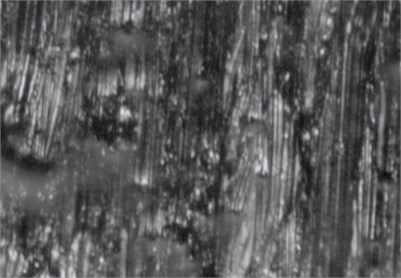
Fig. 9Strand damage transverse to the rolling direction
5. Bending
Bending belongs to the non-cutting procedures during parts processing. Depending upon its hardness, fragility, elasticity, etc. of the different materials can be more or less well bent [3].
If possible at bending process metal sheet’s bending edge has to lie transverse to the rolling direction. The durability is substantially improved thereby. Soft materials should be marked out with the pencil or a brass drawing pin, since the steel needle causes grooves, which can lead to the break of the bending edge. Large metal sheets with long bending edges are appropriately bent at one time throughout the entire length for avoiding unnecessary operations and deformations.
Metal sheets have to be bent parallel as much as possible to the rolling direction, because the microstructure of metal and the contained impurities are stretched during the rolling [4]. If the bending edge lies transverse to the rolling direction, then squeezing folds and on the exterior surface hair-cracks can be developed with a small bending radius on the inner surface. The most important moment when bending is the choice of the correct stamp radius. With the softer material a stamp radius has to be the same or somewhat smaller, than the desired bending radius.
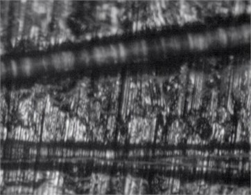
Not all metal sheets are suitable for bending. Therefore, the choice of the correct material is of great importance, because the same rolled materials have different structure. The fragile break can take a place at bending if the material has a small tensile strength and elasticity. As far as it permits the tool, the metal structure has to lie transverse to the bending edge, because the firmness is larger in rolling direction than transverse to the rolling direction. Only in exceptional cases the bending edge and metal structure direction should have the same direction. Breaking the material at the outside edge is the most frequent error during bending (Fig. 10).
Fig. 10Fragile break: a) main view, b) enlarge image
a)
b)
Surface defects and rust on the metal sheet side that is stretched when bending can lead to a substantial reduction of the bending quality. Such defects must be avoided in critical cases.
6. Conclusions
The most important factor is correct selection of part sheet outline, since the construction of the tool depends on it. The correct arrangement of part sheet outline on metal sheet allows to save up to 30 % of the material. The correct punching material choice plays an important role in the sheet-metal working process, because deformation appears in the metal molecular level, causing the crack. The deformations and deviation of parts geometry a lot depends on the rolling direction. Mainly punching forces in all cases depend on the sheet rolling direction as well as the structure of metal. Therefore it is reasonable to apply vibrations during punching process in order to increase the quality of final product.
References
-
Tschaetsch H. Metal forming practice. Springer, 2006, p. 405.
-
Banabic D. Sheet metal forming processes. Springer, 2010, p. 318.
-
Doege Eckart, Behrens Bernd-Arno Handbuch umformtechnik: grundlagen, technologien, maschinen. Springer, 2007, p. 913, (in German).
-
Wei Ching Yeh, Tsu Hsiao Chu The influence of blanking process by superimposing ultrasonic vibrations. Journal of Advanced Materials Research, Vol. 579, 2012, p. 78-85.
-
Wen Tong, Gao Rui, Chen Xia Influence of high frequency vibration on deep drawing process. J. Shanghai Jiaotong Univ. (Sci.), Vol. 17, Issue 4, 2012, p. 456-460.
-
O. B. Martsynyuk, V. Drahobetskyy, A. Markevich Vybroobrabotka deformyruyuschym instrumentom at razdelytelnih operatsyah lystovoyshtampobki. Kremenchug. State. Polytechnic. Univ., Vol. 1, 2009, p. 42-45, (in Russian).
About this article

