Abstract
Unconventional forming method for linear induction drive dynamics is analyzed. This method uses a common secondary element with inductors switching on and off at different times, this way it influences secondary element with double force. Number and type of inductors can be chosen freely. Computer model of multi-inductor drive can enable to create dynamic characteristics of drive force, speed and displacement. Examples of drive speed characteristics are presented.
1. Introduction
In practice, it is often required to guarantee that the actuator of a mechanism at a certain moment or in a particular point of way (shift) would acquire the fixed speed, i.e., it is often a problem forming the drive dynamic characteristics.
Specific features of linear induction motors (LIM) enable to form dynamic characteristics of linear electric drives by unconventional methods [1-3].
This paper analyses the method for forming of dynamic characteristics of the linear induction electric drives with flat construction electrically and magnetically double-sided linear induction motor (LIM), when LIM secondary element is long, and it is commutate by one or more LIM inductors (in the simplest case – two inductors).
2. Multi-inductor linear induction electric drives
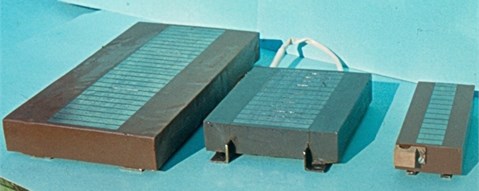
Linear induction electric drive (LIED), where the secondary element is interacting with 4 inductors is shown in Fig. 1. Fig. 2 shows a practical realization of LIM module (Fig. 1-3, 4, 6 and 7). The windings of LIM are filled with compound.
Fig. 1Scheme of multi-inductor linear induction drive: 1, 2, 8 and 9 – commutators; 3, 4, 6 and 7 – inductors of linear induction motor (LIM); 5 – LIM secondary element; v – speed of LIM secondary element
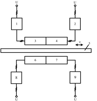
Fig. 2Practical realization of LIM module (the windings of LIM are filled with compound)
Linear induction drive functions as electrically single-sided and magnetically double-sided while switching inductor (3, 4, 6 or 7) with appropriate electrical commutator (1, 2, 8 or 9).
If we switch on the commutators 1 and 8 or 2 and 9 we will get electrically and magnetically double-sided LIM. This type of drive creates twice bigger force for secondary element 5 (Fig. 1) of LIM with appropriate slip. Twice bigger force also can be created while connecting inductors 3 and 7 or 4 and 6 to the industrial electric grid, in this way LIED consist of electrically single-sided and magnetically double-sided LIM with common secondary element 5.
While using electrical commutators to connect any of the three inductors to industrial power grid, secondary element is affected by one electrically and magnetically double-sided and one electrically single-sided or sum of magnetically double-sided force created by linear drive.
In case when all four electrical commutators are switched on, secondary element is affected by the sum of force created by two electrically single-sided and magnetically double-sided LIM. So this type of LIED enables cascade control of force operating to the secondary element. It is possible to control force from 0 (when all commutators are disconnected) to 1, 2, 3 and 4. LIM force can be changed in any way of 5 modes. This allows creating different type of dynamic characteristics of LIED.
It is also possible to have more inductors influencing secondary element than it is shown in Fig. 1, or when instead of some inductors we are using magnetic shunts (steel without wiring). Multi-inductor drive can also consist of different inductor wiring. Besides that speed of big LIED changes slowly so instead of electrical commutators it is possible to use mechanical contacts.
In scientific publications it is shown that small power LIM starting and working currents ratio is near 1 [2]. Therefore there is no need to use thyristor current limiting measures (equipment). Dynamic current amplitudes are small too (Fig. 3). This allows commutating multi-inductor linear induction electric drives inductors by using various laws and this way it is possible to form desirable drive dynamic characteristics.
Fig. 3LIM inductors current oscillograms, when the switching time is 14 (a) and 2.5 (b) periods of industrial electrical mains current
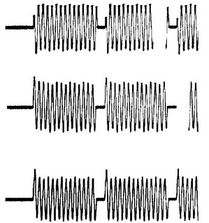
a)
b)
3. Equations in X, Y axis of multi-Inductor electromechanical converter [4, 5]
Investigation of multi-inductor linear induction motor dynamic characteristics is analyzed on base of dynamic mechanical differential equations written in , coordinate system with synchronous speed :
where , – equivalent stator fluxes of two phase machine, , – equivalent rotor winding fluxes, – amplitude of phase voltage, – phase of voltage during power on, – pole pitch, , – synchronous motor speed and motor speed, – force, – static resistant force coefficients [6, 7]:
Other usable notations: – magnetizing reactance; – full inductive reactance of stator winding; – full inductive reactance of rotor winding; – active resistance of stator; – active resistance of secondary element (moving part); – stator and secondary element (moving part) inductive leakage reactance.
Every elementary inductor can be shown as equation with different coefficients. Active and inductive reactance depends on number of winding and cross-section of wire or type of metal (copper, aluminum, etc.). It is also possible to change the sequence of inductor switching together with voltage phase .
It is necessary to consider that speed of secondary element is not equal to zero while solving differential equation (1). Therefore it is necessary to locate changing starting conditions .
The resultant force of secondary element of multi-inductor LIM is calculated with respect to used inductor mode:
where – inductors set; – subset of set, it consists of different type of inductors.
Main equation of moving drive:
Equation to calculate the displacement of secondary element:
4. Computer model of multi-inductor LIM
Computer model of multi-inductor LIM is shown in Fig. 4. Model consist of elements what ensure the LIED transient process imitation, with respect to the fact that during the switching of inductors speed of secondary element does not equal zero (solving differential equations take are into account for the initial conditions).
Fig. 4Computer model of a few LIM inductors with common secondary element
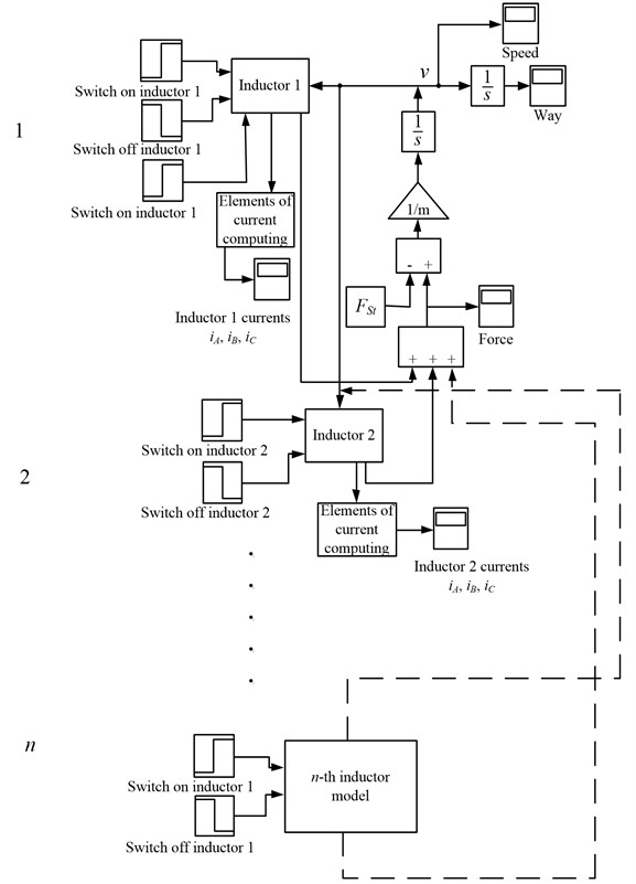
This model (Fig. 4) has a set of settings with a possibility to change the starting time of LIM inductors. Common torque of LIM secondary element is calculated by summarizing every torque produced by inductors (2). The initial parameters sent to the inductors consist of the difference between full torque and static torque.
5. Imitation of multi-inductor linear induction drive
Many types of dynamic characteristics of multi-inductor linear induction drive can be made while using computer model shown in Fig. 4.
Fig. 5 shows the speed dynamic characteristics of linear induction drive with two inductors.
One inductor is turned on at relative time and itspeed up the secondary element during to the speed . At the relative time second inductor is turned on and secondary element reaches the with higher acceleration. Second inductor is turned off at the time this decreases the acceleration and speed to .
Fig. 5Dynamic speed characteristics of LIM, while switching one of the inductors
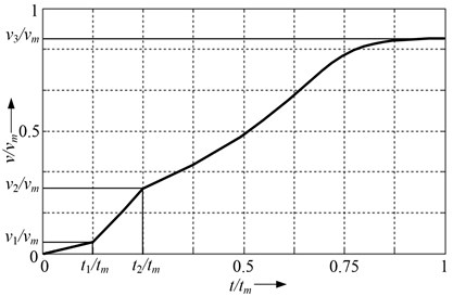
To reach the dynamic results shown in Fig. 5, appropriate setting must be done: “First inductor is turned on“ (Fig. 1) write on the voltage amplitude value and commutation time , and into the second setting window „First inductor is turned off“ – at exact time moment when this inductor must be turned off.
Dynamic speed characteristics of linear induction drive with two inductors are shown in Fig. 6.
Fig. 6Forming of different type of dynamic characteristics
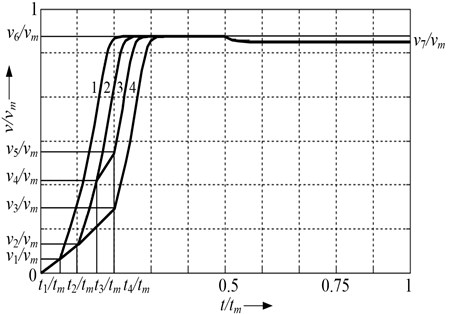
One inductor is turned on at relative time and it speed up the secondary element during to the speed . At that time second inductor is turned on and secondary element reaches the speed with higher acceleration. One of the inductors is turned off at the time . Then LIM inductor produced force equals static force and speed of secondary element decreases to .
To obtain the dynamic speed characteristic 2 of LIM (Fig. 6.), second inductor is turned on later (at relative time ).
To obtain dynamic speed characteristic 3 (Fig. 6) one of the inductors must be turned off and on at time moments and .
Dynamic characteristic 4 is formed as first one, only the second inductor must be turned on later: at the time moments , when relative speed reaches .
In the example (Fig. 6) all the dynamic characteristics are obtained when one of the inductors is turned off at time this way drive works with only one inductor to the end of cycle.
The forming method for linear induction drive dynamic characteristics presented in this article is simpler than other methods for controlling linear induction drives [8-10] what may guarantee the same characteristics of linear induction drives.
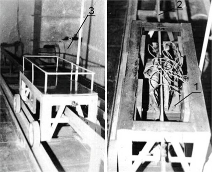
For example, if the carriage drive (Fig. 7) in a certain point of way must acquire a fixed speed, this speed can be guaranteed by the presented method.
Fig. 7Picture of carriage drive: 1 – inductor, 2 – moving element, 3 – load generator
6. Conclusions
New dynamic model and analyzing method for multi-inductor linear electric drive is proposed.
This method for analyzing of LIM allows to use simple, cheaper and more reliable power converters to obtain the same linear electric drive dynamics characteristics.
References
-
Boldea I. Linear electric actuators and their control: a review. Proc. of the 10th International Conference European Power and Drives Association PEMC, Cavtat & Dubrovnik, 2002, p. 12-19.
-
Rinkevičienė R., Poška A. J., Smilgevičius A. Tiesiaeigės mechatroninės sistemos. Teorija ir taikymas. Vilnius: Technika, 2006, p. 224, (in Lithuanian).
-
Smilgevičius A. Tiesiaeigių elektros variklių tyrimai Lietuvoje. Elektronika ir elektrotechnika (Electronics and Electrical Engineering), Vol. 1, 2005, p. 42-47.
-
Rinkevičienė R., Lisauskas S. Control environment of linear induction drives dynamics models. Elektronika ir elektrotechnika (Electronics and Electrical Engineering), Vol. 8, 2007, p. 63-66.
-
Rinkevičienė R., Petrovas A. Dynamic models of controlled linear induction drives. Elektronika ir Elektrotechnika (Electronics and Electrical Engineering), Vol. 5, 2005, p. 23-27.
-
Rinkevičienė R., Lisauskas S. Tiesiaeigių mechatroninių sistemų modeliai. Elektronika ir elektrotechnika (Electronics and Electrical Engineering), Vol. 4, 2003, p. 69-73.
-
Poška A. J., Savickienė Z., Šlepikas A. Control and adjustment of linear induction motor starting force. Elektronika ir elektrotechnika (Electronics and Electrical Engineering), Vol. 2, 2010, p. 21-24.
-
Rinkevičienė R., Lisauskas S., Batkauskas V. Application and analysis of linear induction motors in mechatronic systems. Proc. of the 4th International Symposium Topical problems of Education in the field of Electrical and Power Engineering, Kuressaare, 2007, p. 69-72.
-
Poška A. J., Savickienė Z. Characteristics of unconventionally controlled linear electric drives. Proc. of the 7th International Conference on Electrical and Control Technologies, Kaunas, 2012, p. 217-220.
-
Rinkevičienė R., Savickienė Z., Poška A. J. Performance of linear electric drive at localizing of dust explosions. Elektronika ir elektrotechnika (Electronics and Electrical Engineering), Vol. 6, 2012, p. 101-104.
About this article

