Abstract
This paper presents an efficient and easy methodology for modeling the vibrational behavior of common portable tools using as example a hand-driller. The work described in this paper uses a Hand-Tool model previously developed by the authors and couples it with different Hand-Arm-System (HAS) in order to evaluate which one reproduces the most realistic vibrational behavior. Although proposed for hand-tools, it can be extended for any kind of tool that produces vibration during its operation. This methodology summarizes different techniques in order to analyze the vibrational system. The different components of the hand-driller are represented as lumped masses and the connections between them with a spring and a damper. The elastic constant for the structural elements are determined by FEA using SolidWorks simulations, while the damping constant values used are the recommended by the software 20-sim for structural damping. Once the model is developed, it will be shown how the corresponding Bond-Graph diagram can be obtained and how it helps in obtaining the equations that describe the model. The software 20-sim is used to simulate the developed Bond-Graph model and to determine the Hand-Arm system vibrational response for a specific excitation force.
1. Introduction
Common hand tool vibration can produce several kinds of diseases in workers, when exposed during long periods of time. The HAVS (Hand-Arm Vibration Syndrome) and the Raynaud disease (“dead hand” or white finger) are some of them [1, 2]. This has produced that in recent years several studies have been carried out in order to have a better understanding of these processes and predict the damage that these vibrational phenomena can produce on human health. Many scientists and engineers have developed studies on vibrational behavior of Hand-Arm system, but very few have made an analysis of the mechanical behavior of the tools that produce these vibrations and their interaction with the human body (in this case the Hand-Arm system). In this paper a methodology for the analysis of common hand-tool is exposed, taking into account the influence of the HAS on the system response.
As example, a common portable hand driller was selected for developing its axial vibrational model. The Hand-Tool model was developed by the authors and presented in a conference [3]. The different components of the Black and Decker TM 500 were characterized and divide into groups of lumped masses, coupled between them with a spring and a damper [4, 5]. The equivalent masses and elastic and damping constant were determined. Next, the developed model was coupled to different HAS exposed in [6].
The dynamic model is studied using the Bond Graph technique and the equations that characterize the phenomenon can be easily obtained from this model. The software 20-sim is used to represent the model and solve it. Values of displacement, velocity and acceleration of each component can be easily obtained with this software. Additionally an analysis in frequency variable can be made with 20-sim.
2. Model development
In first place the tool has to be divided into subgroups, each one of them with a specific function and a considerable mass. Fig. 1 presents the Black and Decker TM 500 drill, while in Fig. 2 a schematic representation of the main parts is showed.
Fig. 1Black and Decker TM 500 drill
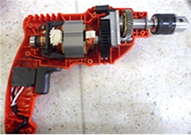
Fig. 2Schematic representation of the drill
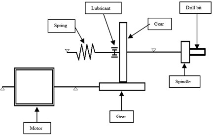
The tool is divided in 5 subsystems: drill bit, spindle, transmission, motor and housing. Each system is represented with lumped masses, and the connections between them are modeled with a spring and a damper [5]. These elements represent the structural elasticity and damping and are different of the springs or dampers that could be in the tool.
Next, elements like spring or dampers (different from the structural ones), which absorb the impact or part of the vibration produced during operation, have to be identified. These elements are the main responsible of the tool dynamic behavior. In the hand driller there is an external spring between the gear and the housing (Fig. 3). It has big influence on the driller axial vibration. There is also lubricant in the gear shaft, which has to be taken into account for the torsional model. Fig. 3 shows the driller axial model, with the 5 main components and the coupling between them.
Fig. 3Drill axial model
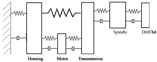
Fig. 4One DOF Hand-Arm model [6]
![One DOF Hand-Arm model [6]](https://static-01.extrica.com/articles/14836/14836-img4.jpg)
The developed model will be coupled to different Hand-Arm System models in order to reproduce the most realistic accelerations. These will be selected from [6], where models from one to four DOF are listed.
The chosen models are listed below, with a simple representation and the values of masses, and elastic and damping constants.
1) One DOF model.
This model was developed by Reynolds and Soedel [6] and is shown in Fig. 4. The values of , and depend on the axis and frequencies of study. For the case of the drill axial vibration the axis of study is the axis (forehand axis) [7] and because the rotational speed of the drill is 2800 rpm, the frequency interval of 20-100 Hz is selected [6].
2) Two DOF model.
The two DOF model will be not used, because the acceleration values are limited to 0.2 g, value that is smaller than the expected accelerations.
3) Three DOF model.
Many 3 DOF models have been developed. Here will be studied the proposed model by the ISO-10068 (Fig. 5).
Fig. 5ISO 10068 Three DOF Hand-Arm model [6]
![ISO 10068 Three DOF Hand-Arm model [6]](https://static-01.extrica.com/articles/14836/14836-img5.jpg)
4) Four DOF model.
Also many 4 DOF models have been developed. Here will be studied the proposed model by the ISO-10068.
Table 1 summarizes the parameters of the three HAS models selected previously.
Table 1Values of the masses, elastic constants and damping constants of the three HAS
DOF | Masses (kg) | Elastic constants (kN/m) | Damping constants (Ns/m) |
1 | 0.103 | 3.65 | 39.5 |
3 | 0.03 0.662 2.9 | 5.335 299.4 2.495 | 227.5 380.6 30.3 |
4 | 0.019 0.0947 0.655 4.29 | 300 68 199 2.04 | 591 203 199 239 |
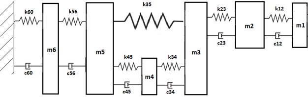
The tool model and the HAS-Model have to be coupled. The complete axial model of the Drill-Hand-Arm system is presented in Fig. 6 and the nomenclature for the different components is shown. There a one DOF model is used. represents the spring that couples the gear and the housing. This spring is very important for the vibrational behavior of the tool.
Fig. 6Axial model of the Drill-Hand-Arm system
Once the two models have been coupled, it is necessary to determine the values of the tool elastic and damping constants. This is show in next subsections.
Simple SolidWorks simulation using FEM can be carried out to determine the structural elastic constants. The components are considered as springs and therefore its deformation will depend on the applied force and the elastic constant, Eq. (1):
where is the elastic rigidity of the component and is the maximum displacement of that component .
For determining the elastic constant of a component, a fixed support boundary condition was placed at one end of the component, while at the other end a force of 1 N is defined. The maximum displacement obtained with the FEA is used to calculate the stiffness of the part.
The maximum deformation of the spindle is 6.297×10⁻¹⁰ m, and the rigidity will be given by Eq. (2):
The same procedure was applied for determining the structural elastic constant of the other component.
Special attention needs to be taken in determining the transmission elastic constant. The gear and worm elastic constant are determided as previously explained. Then, the equivalent gear stiffness related to the worm axis () is calculated by Eq. (3):
where is the gear ratio and its value is 1/10, is the gear spring constant and its value is 1.89322×10⁸ N/m. Then 1.89322×10⁶ N/m.
Finally the equivalent worm-gear set spring constant is calculated by Eq. (4):
Table 2 summarizes all the results.
Table 2Drill components mass, spring and damping constant
Element | Mass (kg) | Elastic constant (N/m) | Damping constant (Ns/m) |
Drill bit | 0.5147 | 8.5034×10⁷ | 158.383 |
Spindle | 0.1923 | 1.588×10⁹ | 1747.49 |
Transmission | 0.2392 | 4.49×10⁶ | 78.2772 |
External spring | – | 2457.7 | – |
Motor | 0.5147 | 6×10⁸ | 1757.16 |
Housing | 0.354 | 48216 | 13.0812 |
One DOF HAS | 0.103 | 3650 | 39.5 |
Its elastic constant can be easily determined using Eq. (5) [8]:
where, is the wire diameter (0.001 m), is the shear modulus of the material (82.7 GPa, A228), is the medium spring diameter (0.0112 m), is the spiral number (3). Therefore 2452.68 N/m.
The spring elastic constant was measured using a force and a displacement sensor, value recorded using software DataStudio. Therefore, measured value is 2167.7 N/m. Then, the theoretical value previously calculated will be used for the ongoing calculations.
There are several ways to calculate the damping constants values associated to stiffness. The damping constant values used are the recommended by the software 20-sim for structural damping. These values are the critical damping values and they can be obtained by Eq. (6):
where, is the lumped mass, is the elastic constant associated to the stiffness of the mass , is the damping constant associated to mass .
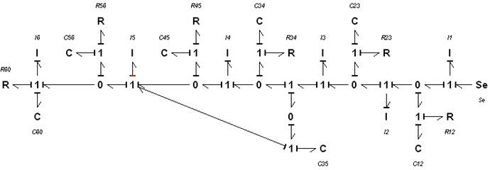
3. Bond graph model and equations
Once all the parameters have been determined it is possible to build the corresponding Bond Graph Model. 20-sim is a software that allows drawing Bond Graph diagrams and simulating the system response under any excitation force [9]. Fig. 7 shows this diagram.
Fig. 7Bond Graph diagram of the driller axial model
Once the diagram was established the equations that represent the model can be easily written, Eq. (7):
where:
where, is the lineal moment of mass , the displacement of mass .
The system response under a specific excitation force can be obtained either with 20-sim simulations or by solving the differential equation. In next sections will be shown results obtained from simulations.
4. Hand-Arm system response
In this paper a methodology for modeling the vibrational behavior of common hand-driller is presented. Therefore, real data to carry out the simulations are used in order to compare the obtained results with the literature and check the benefits of the proposed models and how accurate they reproduce the real data. In this order, the experimented acceleration levels are determined using as excitation force for the model the measured values from [10]. Thrust force values during a concrete drilling operation are shown in Fig. 8.
Fig. 8Axial force experimented by the drill bit during operation. Taken from [10]
![Axial force experimented by the drill bit during operation. Taken from [10]](https://static-01.extrica.com/articles/14836/14836-img8.jpg)
The Hand-Arm system response will be studied for different HAS models. The acceleration experimented by the different HAS models were obtained by a numerical simulation with the 20-sim software.
1) One DOF HAS model.
The acceleration experimented by the one DOF HAS is shown in Fig. 9. The acceleration values correspond to mass , which represents equivalent HAS mass [6].
The maximum acceleration amplitude is 10 m/s2, and the medium value is around 5 m/s2.
2) Three DOF HAS model.
The acceleration experimented by the three DOF HAS is shown in Fig. 10. The acceleration values correspond to mass , which represents the cutaneous part of the hand that is in contact with the tool [6].
The maximum acceleration amplitude is 10 m/s2, and the medium value is around 7 m/s2.
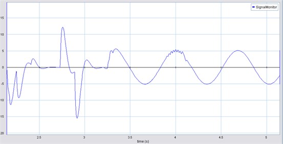
3) Four DOF HA-system model.
The acceleration experimented by the four DOF HAS is shown in Fig. 11.
The acceleration values correspond to mass which represents the dermis [6]. The maximum acceleration amplitude is 10 m/s2, and the medium value is around 5 m/s2.
The acceleration graphs shown do not include the impact. The axis corresponds to acceleration in m/s2 and the axis is time in seconds.
Fig. 9HAS acceleration (m/s2) vs time (s) (one DOF)
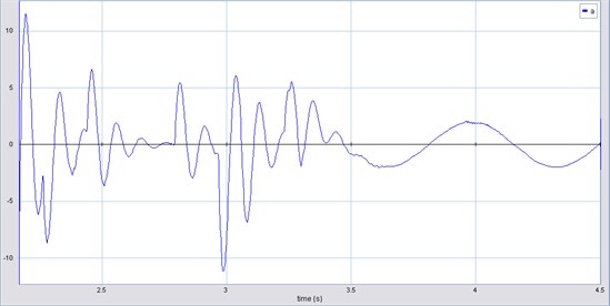
Fig. 10HAS acceleration (m/s2) vs time (s) (three DOF)
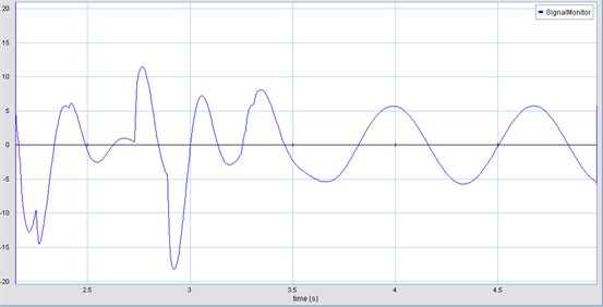
Fig. 11HAS acceleration (m/s2) vs time (s) (four DOF)
5. Conclusions
An analysis methodology has been shown for modeling the vibrational behavior of hand tools using Bond Graph. A sequence of the general procedure has been described.
Obtained values of HAS acceleration have shown that the system response for different HAS models is similar although the three DOF HAS model has reproduced the most realistic accelerations if they are compared with the experimental values presented in Table 3 [11].
Table 3Experimental acceleration values from [11]
Tool | Minimum acceleration amplitude (m/s2) | Medium acceleration amplitude (m/s2) | Maximum acceleration amplitude (m/s2) |
Drill | 3.4 | 6.8 | 10.6 |
This shows that the developed model represents very well the actual behavior of the coupled Hand-Arm-Tool system.
The three DOF HAS model gives a medium value of acceleration amplitude that approaches to the measured in [11] (6.8 m/s2) and requires less computation than the four DOF HAS model. Therefore, three DOF HAS model is the one recommended to use, when analyzing hand-tools vibrational behavior.
References
-
Rakheja S., Wu J., Dong R., Boileau P. E., Schopper A. A comparison of biodynamic models of the human Hand-Arm system for applications to the hand-held power tools. Journal of Sound and Vibration, Vol. 249, Issue 1, 2002, p. 55-82.
-
Lache S., Popovici B. HAV – an interdisciplinary engineering and medical study. Fascicle of Management and Technological Engineering, Vol. 6. 2007, p. 536-541.
-
Ruiz D., Galviz J., Hernandez R. J., Zurek E. Bond-Graph model of axial vibrations in a Drill-Hand-Arm system. Proceedings of the 2013 IEEE International Instrumentation and Measurement Technology Conference – I2MTC, Minneapolis, 2013, p. 49-52.
-
Kadam R. Vibration characterization and numerical modeling of a pneumatic impact hammer. MS Thesis, Master of Science in Mechanical Engineering, Blacksburg, Virginia, Virginia Polytechnic Institute and State University, 2006, p. 1-141.
-
Forestier F., Gagnol V., Ray P. Modeling of self-vibratory drilling head-spindle system for predictions of bearings lifespan. Advances in Acoustics and Vibration, Vol. 2011, 2011, p. 1-10.
-
Rakheja S., Wu J., Dong R. A comparison of biodynamic models of the human Hand-Arm system for applications to hand-held power tools. Journal of Sound and Vibration, Vol. 249, 2002, p. 55-82.
-
Hosoya N., Maeda S. Establishment of an experimental system for measuring biodynamic response of Hand-Arm. Proceeding of the First American Conference on Human Vibration, Vol. 1, 2006, p. 136-137.
-
Budynas R., Keith J. Shigley’s mechanical engineering design. McGraw-Hill, 9th Edition, 2010, p. 1082.
-
Parra J. Equation’s system for vehicle pitching modeling using bond graph. Theoria, Vol. 17, 2008, p. 63-73.
-
Furness R., Galip A. Dynamic modeling of the thrust force and torque for drilling. American Control Conference, United States, Chicago, 1992, p. 384-390.
-
Santurio J., Rodriguez J., Argüelles E. Study of Hand-Arm vibration exposure hazard when using hand-tool machines. Project SV-PA-04-09, The University of Oviedo, Spain, 2006, p. 1-127.
About this article

We would like to thank our colleague and friend Eng. Luis Echeverri for sharing his idea on studying the vibrational phenomena on hand tools.
We would like to thank the Universidad del Norte’s Physics Laboratory, for their support on the required experimental procedure.
