Abstract
Numerous epidemiological studies have shown that operators who use hand-held power tools are prone to develop hand-arm vibration syndrome. Therefore, it is necessary to reduce the tool vibrations to protect the worker’s health. This research focuses on the dynamic modeling and the vibration simulation of orbital sanders which are commonly used in industrial sectors. The mathematic model with eighteen degrees-of-freedom (DOF) of this machine is established based upon the Lagrange equation. The experiments are also conducted to test vibrations at the top of the housing where the operators hold the machine. The simulated results are found in good coincidence with the experimental results, and the errors between the experimental results and the simulated values are in acceptable range, which demonstrates the mathematic model in this paper is accurate.
1. Introduction
Exposure to hand-transmitted vibration arising from hand-held power tools for a long time is more prone to several disorders of the hand and arm, which are collectively termed as hand-arm vibration syndrome (HAVS). Therefore, it is necessary to decrease tool vibrations to protect the worker’s health from the HAVS [1, 2]. Goglia et al. [3] obtained the daily exposure time within the safety limit according to ISO standard. According to several studies [4], some effective methods were adopted in the tool design process. However, the experiment showed that about 15 % of these tools exceeded the safety limits according to applicable standards [5]. Thus, the vibration suppression should be significant and urgent to decrease the damage to the operators. Mazlan and Ripin[6] established a three-degree-of-freedom dynamic model of the orbital sander. There were also some researches about the vibration reduction of grass trimmer vibration [7, 8]. Furthermore, Rakheja et al. [9] and Yan et al. [10] both provided a hammer dynamic model based on some simple assumptions.
In this paper, an accurate mathematic model with eighteen degrees-of-freedom (DOF) of orbital sanders is proposed, which is time-saving compared with the ADAMS model. Furthermore, the experiment that validates the accuracy of the dynamic model is implemented by testing the acceleration values at the top of housing, and the stiffness values of the bearings are selected with minimum errors between the experiment and the simulation results.
2. Mathematic modeling of orbital sander
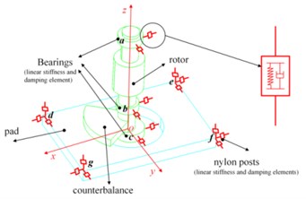
The hand-held orbital sander machine is shown in Fig. 1. Usually, sanders can be simplified into three main parts, housing, rotor and pad, respectively, which are connected by bearings and soft nylon posts. Fig. 2 presents the diagram of a sander which is used in the following mathematic modelling. From this diagram, the rotor system is supported by three closely deep groove ball bearings. Two bearings located at position and are used to connect the rotor and the housing. The third bearing located at position connects the rotor and the pad, and its axis is not coincident with the rotation axis. In addition, the links between the housing and the pad are provided by four soft posts which are located at the position , , and . All the bearings and posts are characterized by linear stiffness and damping elements in the dynamic model.
As the orbital sander vibrations exist in all six directions, especially the rotor’s vibration, the effect of cross coupling in , and axes should be taken into account. Thus, each part has six degrees of freedom, and Cardan angle coordinates are used to describe the space motion of the three orbital sander components. A right hand coordinate system - is adopted to define the system static coordinate whose origin is in the middle surface of the pad. The axis of this fixed coordinate coincides with the axis of rotation, which is presented in Fig. 2. Moreover, the rotating Cartesian coordinates of these parts are expressed by -’’’ whose origins are fixed in the position of the barycentre of these parts, and the initial axes directions of these body-fixed coordinates are the same as the space-fixed coordinate. The subscript ( 1, 2, 3) of the variables in this following dynamic modelling represents the different parts of the machine. The letter equaling 1, 2 and 3 shows it represents the housing, the rotor and the pad, respectively. Thus, the orbital sanding machine system can be modelled by an eighteen degrees-of-freedom (DOF) dynamical system, including the vibration motions along the axis, axis and axis expressed by , and and the angular motions of the rotating Cartesian coordinates relatively to the static coordinate represented by Cardan angles, namely, , and . The masses and the inertial tensor of these parts relatively to their body-fixed are written with the mass matrix ( 1, 2, 3) and ( 1, 2, 3) in the following equations.
Fig. 1Components of orbital sander
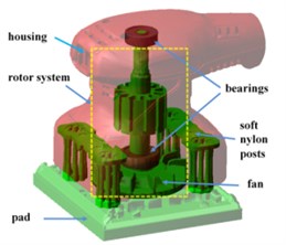
Fig. 2Dynamic model of orbital sander
In order to obtain the system dynamic model based on the Lagrange equation, the system kinetic energy, potential energy and energy dissipation should be calculated. The total kinetic energy of the system includes the kinetic energy of the housing , the rotor kinetic energy and the pad kinetic energy . Because the housing does not have large displacement motion, the linear velocity vector and the angular velocity vector of the housing can be expressed as Eq. (1). Generally, the complex kinetic energy of the housing can be decomposed into two simple components, so the kinetic energy of the housing can be expressed by Eq. (2):
Because of the eccentricity of the rotor and the pad, their mass centres are not in the axis of rotor. Therefore, the large rigid displacement of the rotor centre should be considered when the kinetic energy is calculated. According to the centre position of the initial time and the centre trajectory, the total linear displacement and the velocity of the mass centre can be obtained from the Eqs. (3) and (4), where represents the radius of the trajectory of the rotor centre, and represents the speed of the rotor:
Thus, , can be expressed as Eq. (5), and the kinetic energy of the rotor is now presented as Eq. (6):
Besides the rotor, the pad also has the large rigid translational degree of freedom and the centre of mass moves in a circle. Therefore, the total linear displacement and the velocity of the pad can be written as Eq. (7), where represents the length from the pad centre to the axis of rotor:
However, the pad only contains the translational motion and do not revolve round its own axis in a large displacement, so , can be expressed as Eq. (9), and the kinetic energy of the pad can be expressed as Eq. (10):
Therefore, the total kinetic energy of the system can be obtained through Eqs. (2), (6) and (10):
The sander system potential energy includes the elastic energy of the post and the contact energy of the bearings. The stiffness of element () are expressed by , and in three directions. The displacement of the point of the part at the stiffness and damping element in the static coordinate system can be expressed as follows:
where represents the transformational matrix of the component from the rotating Cartesian coordinates to the fixed coordinate. represents the point coordinate of the part at the stiffness and damping elements () in the rotating Cartesian coordinates and it is written as .
Therefore, the potential energy of elements () connected the part and part can be expressed as Eq. (13), where , and are the three components of the stiffness:
Energy dissipation of the system is caused by the contact damping provided by the bearings and the material damping arising from the posts between the pad and the housing. The damping coefficient of the stiffness and damping element () is expressed by , and in three directions.The linear velocity of the point where the stiffness and damping element located of the part in the fixed coordinates system during the free running of the sander machine can be expressed as Eq. (14):
where is the antisymmetric matrix of vector , and is the angular velocities of these parts in the static coordinate. Therefore, the energy dissipation of the element () between the part and part can be given by Eq. (15):
So, the system total potential energy and the total energy dissipation of the system can be written as Eq. (16):
Then, Lagrange method was employed to build the mathematic model of the orbital sanders, and the Lagrange equation is:
where represents the generalized coordinates and is the generalized actuation force:
In this paper, the machine is considered under the free running condition, so the matrix equals 0. Therefore, with the expression , and , the vibrations of the sanders can be obtained through the Lagrange equation and numerical solution methods.
3. Numerical simulation and experiment verification
In the mathematic model, the radial and axial stiffness are calculated as 11 N/mm and 600 N/mm by the finite-element method. In addition, considering the clearance of the bearings in this machine, the order of value is set as 106N/m in this research. The damping coefficient is about 200 Ns/m according to the experience. Therefore, the acceleration values of the sander machine can be obtained through Runge-Kutta methods with Eq. (17). The stiffness values of these bearings are selected in such a way that the error between the measured accelerations and the simulated results reaching the minimum value, and the formula of error is presented in Eq. (18):
In this equation, represents the point number. , and is the experimental values along three directions. , and is the simulated values along different axes.
In order to validate the accuracy of the mathematic model of the orbital sander, experiments are carried out by testing acceleration values of the housing. Fig. 3 illustrates the method to measure the housing accelerations with the orbital sander hanged by a string, and the positions to test the values marked as point 1# and point 2#. Thus, vibration responses along the , and axes at these two positions can be obtained, respectively.
Through the above experiment and the numerical calculation of the dynamic model, the stiffness of the deep groove ball bearings can be obtained by the optimization methods. The values of these three bearing stiffness are 2.5e6 N/m, 1.4e6 N/m and 2.2e6 N/m, respectively. The comparisons of frequency domain curve of the accelerations along three directions are shown in Fig. 4. It clearly shows that the main frequency the vibration signal is the excitation frequency determined by the rotor speed, and the acceleration value at the fundamental frequency accounts for the main part of the vibration, which is caused by the unbalanced force. Because of the small acceleration values of the direction, the errors in frequency domain are the maximum, especially at the point 1#. However, the error can be acceptable also due to its small values compared with other directions. In this research, we focus on the optimization of the unbalance to reduce the housing vibrations. Further, the accurate vibration data are also presented in Fig. 5. In this figure, , and are the root mean square (RMS) of accelerations along the three axes, and () represents the total value of the vibrations defined in Standard ISO 5349 by synthesizing the accelerations along the three axes (, , ).
Fig. 3The experiment to measure the acceleration of the housing
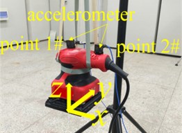
Fig. 4The frequency domain curve of simulated and experiment: a) point1#, b) point 2#
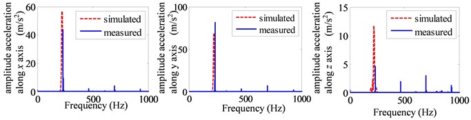
a)
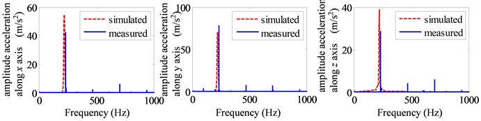
b)
Fig. 5 illustrates the values of the measured accelerations, the simulated results, and the errors between them. From this figure, it can be seen that the maximum absolute error of the accelerations is about 9.1 m/s2, and the errors along y axis are larger than the other directions. Furthermore, the maximum relative errors of these data are about 20 %. However, the maximum absolute and relative errors of the total accelerations at the two points expressed by are 3.9 m/s2, 6 % and 2.7 m/s2, 4 %, respectively, which is within acceptable ranges. In fact, the synthetic values are the most significant data and usually used as the standard of evaluation for the orbital sanders. In addition, the errors may be caused by some assumptions about the system during the mathematic modeling and some manufacturing errors, for example, the components which are assumed as rigid parts in this paper are flexible of the actual machine. Through the above error analysis, it is clearly that the dynamic model of the sander is accurate enough compared with the experiments. Thus, it is possible to quickly predict the vibration values of the housing based on this model and carry out the following vibration optimization of the sander in this paper.
Fig. 5The simulated and experimental acceleration of the housing: a) point 1#, b) point 2#
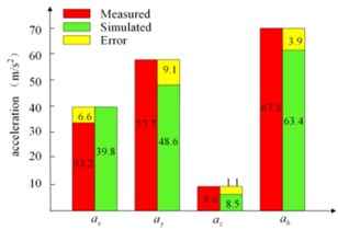
a)
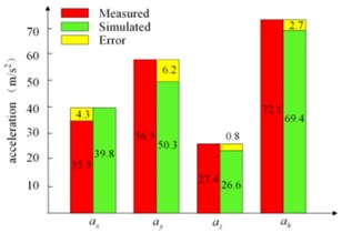
b)
4. Conclusions
This paper focuses on the dynamic modeling and housing vibration simulation of the orbital sander. A mathematic model of the orbital sander with eighteen degrees-of-freedom (DOF) is provided in this paper, which clearly represent its dynamic characteristics. The error of the total accelerations between experiment and simulation which should be most considered is within the acceptable ranges. Furthermore, in future, studies about the influences of the major parameters to the system vibrations based on this mathematic model are vital and should be taken into account. It can improve the basic theoretical research of the dynamic characteristics of the orbital sanders, which is useful for reducing the hand-held power tools vibrations to protect human health.
References
-
Bovenzi M., et al. Work-related disorders of the upper limb in female workers using orbital sanders. International Archives of Occupational and Environmental Health, Vol. 78, Issue 4, 2005, p. 303-310.
-
Gauthier F., Gélinas D., Marcotte P. Vibration of portable orbital sanders and its impact on the development of work-related musculoskeletal disorders in the furniture industry. Computers and Industrial Engineering, Vol. 62, Issue 4, 2012, p. 762-769.
-
Goglia V., Risović S., Beljo R. Hand transmitted vibrations caused by orbital hand sanding machines. Archives of Industrial Hygiene and Toxicology, Vol. 46, Issue 1, 1995, p. 33-43.
-
Greenslade E., Larsson T. J. Reducing vibration exposure from hand-held grinding, sanding and polishing power tools by improvement in equipment and industrial processes. Safety Science, Vol. 25, Issues 1-3, 1997, p. 143-152.
-
Vergara M., et al. A hand-transmitted vibration in power tools: Accomplishment of standards and users ‘perception. International Journal of Industrial Ergonomics, Vol. 38, Issues 9-10, 2008, p. 652-660.
-
Mazlan A. Z. A., Ripin Z. M. Active vibration control to attenuate hand-arm vibration from orbital sander: a mathematical model approach. Indian Journal of Science and Technology, Vol. 8, Issue 30, 2015, p. 2-8.
-
Mallick Z. Optimization of operating parameters for a back-pack type grass trimmer. International Journal of Industrial Ergonomics, Vol. 38, Issue 1, 2008, p. 101-110.
-
Ko Y. H., Ean O. L., Ripin Z. M. The design and development of suspended handles for reducing hand-arm vibration in petrol driven grass trimmer. International Journal of Industrial Ergonomics, Vol. 41, Issue 5, 2011, p. 459-470.
-
Rakheja S., Rajalingham C., Boileau P. E. Analysis of hand-transmitted vibration of a hand-held percussive tool. European Journal of Mechanical and Environmental Engineering, Vol. 47, Issue 3, 2002, p. 141-156.
-
Yan S., Huang S., Zou F. Analysis of the dynamic characteristics of gas chamber in rotary hammer. Journal of Advanced Mechanical Design, Systems, and Manufacturing, Vol. 10, Issue 4, 2016, p. JAMDSM0066.
About this article

