Abstract
The new two-degree-of-freedom hybrid-driven seven-bar mechanical presses with rotational and linear input links are presented. The rams of the proposed presses can generate two same required output cycles during a single input cycle. The rotational input link rotates with a constant angular speed, and the linear input link follows a reciprocating motion along a specified linear guide fixed on the rotational input link. The configuration, solid model, kinematic analysis, motion trajectory design of the linear input link, and optimization of the dimensional synthesis of the proposed presses are described. An example is provided to verify the feasibility and effectiveness of this methodology.
1. Introduction
Mechanical presses are widely used in manufacturing industries today. They can have either single-driven or hybrid-driven mechanisms. Studies on the former have focused on obtaining or improving the kinematic or dynamic performance of presses by combining the concept of variable input speed into design methods. Yossifon and Shivpuri [1, 2] designed a servomotor-controlled double-knuckle mechanical press for precision forming. Yan and Chen [3-5] proposed a novel approach by varying the input speed of the crank to make the ram’s motion suitable for both deep-drawing and precision-cutting processes. Hsieh [6, 7] proposed a novel design approach for cam-controlled planetary gear trains to generate variable input speeds. Mundo et al. [8] presented an optimal design method for mechanical presses driven by cam-integrated linkages. Hsieh and Tsai [9-11] designed a new press system with six links driven by an Oldham coupling for precision deep drawing. Soong [12] proposed a method to obtain the desired kinematic performance for mechanical presses by varying the length of the driving links.
The concept of a hybrid mechanism, also called a controllable mechanism or hybrid machine, has also been used recently to design mechanical presses. Du and Gue [13] and Guo et al. [14] proposed an optimal design method for synthesizing a two-degree-of-freedom (2-DOF) seven-bar linkage mechanism driven by a large constant-speed motor and a small servomotor. The resulting mechanism was flexible and energy efficient. Meng et al. [15] designed a hybrid-driven seven-bar linkage mechanical press by using inverse kinematic analysis and optimal synthesis. Li and Tso [16] proposed an iterative learning control scheme for a hybrid-driven servo press and experimentally verified the expected improvement of the pouch position errors and precision. Soong [17] proposed a design method for adjustable mechanical forming presses that have a length-adjustable link. Li and Zhang [18, 19] proposed a two-step optimization process to design seven-bar and nine-bar hybrid-driven presses for precision drawing. The optimum link dimensions and motion trajectories of the servomotor were determined, and the mechanisms had programmable output motion, higher load capabilities, higher production rates, and lower costs. Soong [20] proposed a new linkage mechanism with a rotational input and a direct linear input. It could satisfy different desired design requirements by controlling the motion trajectories of the two input links.
This paper proposes a new design method for mechanical forming presses whose ram can generate two same required output cycles corresponding to every single input cycle. The configuration, kinematic analysis, motion trajectory design of the linear input link, and optimal dimensional synthesis of the new presses are described. An example is introduced to demonstrate the feasibility and effectiveness of this design methodology.
2. The new mechanical presses
The new mechanical forming press presented in this paper is a 2-DOF hybrid-driven seven-bar mechanical press with a rotational input link and a linear input link. The configuration of the proposed press is shown in Fig. 1. It has two slider links: one is the linear input link, and the other is the ram of the press. The rotational input link is designed as a disk link and is driven by a constant-speed motor. The linear input link is driven by a linear motor that is fixed on the rotational input link; its centerline passes through the center of the rotational input link. The ram of the proposed press can generate two same required output cycles during a single input cycle. The rotational input link rotates with a constant angular speed, and the linear input link follows a reciprocating linear motion along the centerline of the linear motor fixed on rotational input link. The proposed press degenerates to a six-bar Watt or Stevenson press when the linear input link is fixed. Therefore, the proposed press can be regarded as a six-bar Watt or Stevenson press with a variable input link length, as shown in Fig. 1(a) and (b), respectively.
Fig. 1The new mechanical presses with a variable length of the input link
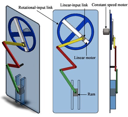
a) Watt type press
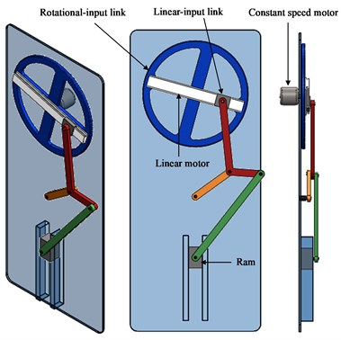
b) Stevenson type press
3. Motion trajectory design of the linear input link
The linear input link has to complete a reciprocating linear motion along the guide to generate two output cycles while the rotational-input link completes one cycle, as shown in Fig. 1. Therefore, we assumed that the position of the linear input link was a function of the angular position of the rotational input link. The instantaneous motion trajectory of the linear input link can be expressed as simple harmonic motion that is a function of the angular position of the rotational input link at any moment during a cycle as follows:
where:
In these equations, is the position of the linear input link, is the angular position of the rotational input link, is the initial angular position of the rotational input link, is the angular velocity of the rotational input link, and is the radius of the rotational input link. When the linear input link is at point , as shown in Fig. 2, 0; therefore, .
Fig. 2The coordinate systems of the new mechanical presses
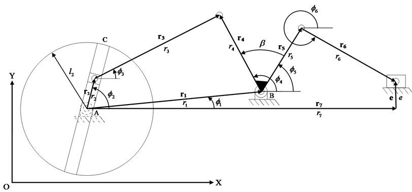
a) The coordinate system of Watt type press with a variable length of the input link
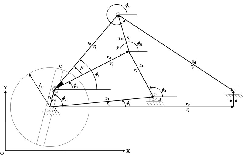
b) The coordinate system of Stevenson type with a variable length of the input link
4. Kinematic analysis
According to the coordinate systems shown in Fig. 2, the loop-closure equation can be written as:
and
Rearranging and solving these two equations, the angular position of links 4 and 3 can be given as:
where:
Differentiating Eq. (5) with respect to time and expressing the results in terms of and :
where:
By differentiating Eq. (5) with respect to time twice, we can solve these two simultaneous equations:
where:
For a Watt press, since , , and , then according to the coordinate system shown in Fig. 2(a), the angular displacement, velocity, and acceleration of link 6 can be written as:
respectively.
The linear displacement, velocity, and acceleration of the ram can be written as:
respectively.
For a Stevenson press, since , , and , then according to the coordinate system shown in Fig. 2(b), the angular displacement, velocity, and acceleration of link 6 can be written as:
respectively.
The linear displacement, velocity, and acceleration of the ram can be written as:
respectively.
5. Optimization of the design
An optimization procedure was applied to determine the design variables while ensuring the desired performance. The general optimization equations can be defined as follows.
Minimize:
Subject to:
and
where gives the desired objective functions, denotes the number of the desired objective functions, and and give the number of equality and inequality constrained equations, respectively. Note that the equality and inequality constraints are defined to obtain the desired performance.
Any optimization method can be used to determine the design variables. We solved the optimum dimension synthesis problem by applying the “fmincon” function in the optimization toolbox of the Matlab software package.
6. Example and discussion
In this section, an example is given to demonstrate the feasibility of this proposed approach. First, we assumed that the proposed press had the same dimensions as a reference press. We let the linear input link move following simple harmonic motion while the rotational input link rotated at a constant speed of 60 rpm during a cycle to verify that the ram of the proposed press could generate two output cycles. Then, using the same input conditions, we conducted a dimensional synthesis to obtain the desired output motion using the same stroke as the reference press.
In this example, two same output cycles, during which the ram maintains an approximately constant speed over a specific period before forming for precision deep drawing, were desired during one cycle of a Stevenson press with a variable input link length, as shown in Fig 1(b). The optimization was used to synthesize the optimal dimensions of the proposed press. The dimensions of the existing reference press are shown in Table 1.
Table 1Dimensions of an existing reference press
Dimensions | (°) | (mm) | (mm) | (mm) | (mm) | (mm) | (mm) | (mm) | (mm) |
Values | 0 | 276.08 | 81.16 | 142.12 | 243.49 | 204.63 | 367.30 | –141.69 | 0 |
The objective function can be defined as follows.
Minimize:
subject to:
Figures 3 and 4 compare the reference press with the proposed non-optimized and optimized presses, respectively, in terms of displacement, velocity, and acceleration of the ram. The optimal dimensions of the proposed press are shown in Table 2.
Table 2Optimized dimensions of the proposed press
Dimensions | (°) | (mm) | (mm) | (mm) | (mm) | (mm) | (mm) | (mm) | (mm) | |
Values | 0 | 410.58 | 77.67 | 117.50 | 385.33 | 151.61 | 502.35 | 441.19 | 90.48 | 166.24 |
Figure 3 indicates that the ram did generate two same output cycles, but their strokes and kinematic performance did not satisfy the original design requirements. After optimization, the results (Fig. 4) indicated that the ram did generate two same output cycles whose strokes were the same as that of the reference press, and it had a steadier velocity period before BDC during the forming process than the reference press did for precision deep drawing.
The desired output motion characteristics for example were achieved as expected, as shown in Figure 4, respectively, but the peak ram acceleration was higher than the reference value, even after the optimization. This was the only cost paid for our proposed design method.
The results of this example suggest that mechanisms with two same output cycles corresponding to one input cycle are possible and feasible to design. The proposed mechanism doubled the efficiency of the original one.
Fig. 3The comparisons between the reference and proposed non-optimized press in displacement, velocity and acceleration of the ram
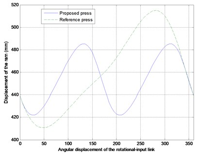
a) Displacement
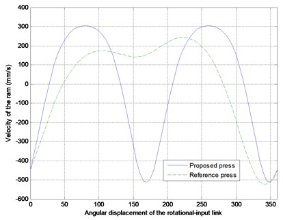
b) Velocity
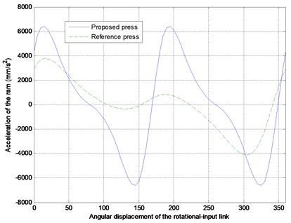
c) Acceleration
7. Conclusion
A novel 2-DOF hybrid-driven seven-bar mechanical press with a rotational input link and a linear input link was presented. The ram of the proposed press could generate two same required output cycles during a single input cycle. The rotational input link rotated at a constant speed, and the linear input link followed a reciprocating motion along a specified linear guide fixed on the rotational input link. This design method increased the efficiency of the proposed press over that of the original one. The configuration of the proposed press was described, along with the motion trajectory design of the linear input link. A kinematic analysis was performed using the loop-closure equation for two types of presses. Then, the optimized dimensions of the proposed presses were found. An example was used to verify the feasibility and effectiveness of this methodology.
Fig. 4The comparisons between the reference and proposed optimized press in displacement, velocity and acceleration of the ram
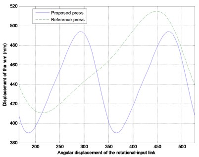
a) Displacement
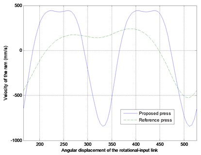
b) Velocity
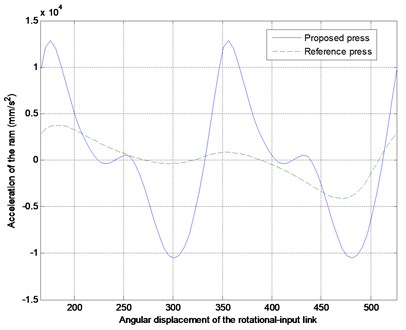
c) Acceleration
References
-
Yossifon S., Shivpuri R. Design considerations of the electric servo-motor driven 30 ton double knuckle press for precision forming. International Journal of Machine Tools & Manufacture, Vol. 33, Issue 2, 1993, p. 209-222.
-
Yossifon S., Messerly D., Kropp E., Shivpuri R., Altan A. A servo motor driven multi-action press for sheet metal forming. International Journal of Machine Tools & Manufacture, Vol. 31, Issue 3, 1991, p. 345-359.
-
Yan H. S., Chen W. R. On the output motion characteristics of variable speed input servo-controlled slider-crank mechanisms. Mechanism and Machine Theory, Vol. 35, Issue 4, 2000, p. 541-561.
-
Yan H. S., Chen W. R. A variable input speed approach for improving the output motion characteristics of Watt-type presses. International Journal of Machine Tools & Manufacture, Vol. 40, Issue 5, 2000, p. 675-690.
-
Yan H. S., Chen W. R. Optimized kinematics properties for Stevenson-type presses with variable input speed approach. Transaction of the ASME, Journal of Mechanical Design, Vol. 124, Issue 3, 2002, p. 350-354.
-
Hsieh W. H. An experimental study on cam controlled planetary gear trains. Mechanism and Machine Theory, Vol. 42, Issue 5, 2007, p. 513-525.
-
Hsieh W. H. Kinematic synthesis of cam controlled planetary gear trains. Mechanism and Machine Theory, Vol. 44, Issue 5, 2009, p. 873-895.
-
Mundo D., Danieli G., Yan H. S. Kinematic optimization of mechanical presses by optimal synthesis of cam-integrated linkages. Transactions of the Canadian Society for Mechanical Engineering, Vol. 30, Issue 4, 2006, p. 519-532.
-
Hsieh W. H., Tsai C. H. A study on a novel quick return mechanism. Transactions of the Canadian Society for Mechanical Engineering, Vol. 33, Issue 3, 2009, p. 139-152.
-
Hsieh W. H., Tsai C. H. On a novel press system with six links for precision deep drawing. Mechanism and Machine Theory, Vol. 46, Issue 2, 2011, p. 239-252.
-
Hsieh W. H., Tsai C. H. Optimum design of a novel press system with Stephenson-I mechanism. Computers and Mathematics with Applications, Vol. 64, Issue 5, 2012, p. 897-907.
-
Soong R. C. A new design method for single DOF mechanical presses with variable speeds and length-adjustable driving links. Mechanism and Machine Theory, Vol. 45, Issue 3, 2010, p. 496-510.
-
Du R., Guo W. Z. The design of a new metal forming press with controllable mechanism. Transaction of the ASME, Journal of Mechanical Design, Vol. 125, Issue 3, 2003, p. 582-592.
-
Guo W. Z., He K., Yeung K., Du R. A new type of controllable mechanical press: motion control and experiment validation. Transaction of the ASME, Journal of Mechanical Design, Vol. 127, Issue 4, 2005, p. 731-742.
-
Meng C. F., Zhang C., Lu Y. H., Shen Z. G. Optimal design and control of a novel press with an extra motor. Mechanism and Machine Theory, Vol. 39, Issue 8, 2004, p. 811-818.
-
Li C. H., Tso P. L. Experiment study on a hybrid-driven servo press using iterative learning control. International Journal of Machine Tools & Manufacture, Vol. 48, Issue 2, 2008, p. 209-219.
-
Soong R. C. An adjustable six-bar mechanism with variable input speed for mechanical forming presses. Transactions of the Canadian Society for Mechanical Engineering, Vol. 32, Issues 3-4, 2008, p. 453-466.
-
Li H., Zhang Y. Seven-bar mechanical press with hybrid-driven mechanism for deep drawing, Part 1: Kinematic analysis and optimum design. Journal of Mechanical Science and Technology, Vol. 24, Issue 11, 2010, p. 2153-2160.
-
Li H., Zhang Y. Seven-bar mechanical press with hybrid-driven mechanism for deep drawing, Part 2: Dynamic modeling and simulation. Journal of Mechanical Science and Technology, Vol. 24, Issue 11, 2010, p. 2161-2167.
-
Soong R. C. A design approach for flexible linkage mechanisms with a rotational and a linear input. Advanced Science Letters, Vol. 9, 2012, p. 499-504.
About this article

The author is grateful to the National Science Council of the Republic of China (Taiwan, R. O. C.) for supporting this research under grant NSC 100-222-E-224-008.
