Abstract
The desired preloading effect of a hydraulic press frame parts (upper/lower semi-circular beams and columns) with Pre-Tightening Stress (PTS) by means of Winding Steel Wires (WSW), which is directly related to the reliability and normal safe operation of the hydraulic press. The deformation of the Hydraulic Press Column (HPC) is an important indicator of the optimal preloading effect of the hydraulic press. As a technical bottleneck, the continuous cumulative deformation of a HPC under seven time-varying steps is critical issues especially in theoretically calculated for a 20 MN double-frame hydraulic press with PTS using WAW. A solid model with a PTS frame is pre-designed by 3D software, and two simulation methods, equivalent pressure loading and equivalent temperature loading, are used to simulate and analyze the continuous cumulative deformation of the HPC under each step in Ansys Workbench software. By comparing the deformation and error analysis in the three cases above, the feasibility of the two simulation methods is verified, which leads to the advantages and disadvantages of each method in order to guide the subsequent design.
Highlights
- The desired preload effect of a pre-stressed wire-winding hydraulic press is directly related to the reliability and normal safe operation of the hydraulic press.
- The continuous cumulative deformation of a hydraulic press column under seven time-varying steps is theoretically calculated for a 20MN double-frame pre-stressed wire-winding hydraulic press.
- The continuous cumulative deformation of the hydraulic press column under each step in Ansys Workbench software is simulated and analyzed.
- A solid model with a pre-stressed frame is pre-designed by 3D software.
- By comparing the deformation and error analysis in the three cases above, the feasibility of the two simulation methods is verified.
1. Introduction
With the rapid development of industrialization, large forging and hydraulic press has been widely used in the fields of aviation, aerospace, shipping, national defense and military fields, etc. It has become an important indicator of a country's manufacturing level and industrial development capability [1-5]. Compared with traditional large hydraulic presses with four-columns, prestressed wire-winding hydraulic presses have the advantages of high fatigue strength, high load-bearing capacity, and no abrupt failure, therefore, prestressed wire- hydraulic presses using winding steel wires have been used in more and more industrial fields [6-10]. At present, the design of prestressed WSW hydraulic presses is still based on the traditional mechanical equations and theoretical model calculations to determine the structural size parameters and winding process of the hydraulic presses, while there are certain structural differences between the actual produced hydraulic presses and the theoretical model, which leads to the deviation of the calculated results from the actual values. With the continuous improvement of computer computing power, computer simulations based on FEA methods have been increasingly used in various fields of analysis and calculation [11-15]. The use of FEA software for mechanical analysis and calculation of hydraulic presses can simulate the actual model and actual working conditions more realistically, and the results are more accurate [8, 16-17].
The prestressed wire winding process is the key technology of the prestressed wire winding. The standard for measuring whether the process meets the standards is the vertical deformation of the HPC by means of WSW is pre-tightened. In this subject, the theoretical calculation, the simulation analysis of the equivalent pressure loading method and the simulation analysis of the cooling and pressurization method are used, and the three values are compared and analyzed to obtain the deformation of the HPC in the vertical direction, and the feasibility of the two simulation methods is verified.
2. Theoretical calculation of HPC deformation with PTS using WSW
The deformation of the HPC of the 20 MN double-frame with PTS using WSW in the vertical direction is calculated according to the existing theoretical formula. The allowable value of the preload factor η of the hydraulic press is 1.2±0.01, and the error between the theoretical and simulated values of the deformation of the HPC in the vertical direction is within 5 %.
2.1. Structural dimensional parameters
It is known that the width of the upper and lower semicircular beams of the single frame of the 20 MN double frame hydraulic press with PTS using WSW is 1190 mm, the radius is 1225 mm, the width of the HPC is 1190 mm, the thickness is 350 mm, and the length is 3880 mm. the number of WSWs laid in each layer is 176, and the WSWs are made of flat WSWs whose length is 5 mm and width is 1.5 mm. the basic dimensional parameters of the frame model as shown in Fig. 1.
Fig. 1PTS frame model structure size parameters
The winding method of steel wire is divided into 7 steps with variable tension, and the number of layers of each step is 5, 6, 8, 9, 12, 14 and 15, so the total number of layers of steel wire is 69, and the permitted tensile force of a steel wire is 1000 kg.
The material parameters of the upper and lower semicircular beams, HPCs and wires are shown in Table 1.
Table 1Material parameters for each part of the frame
Name | Density (Kg/m3) | Young’s modulus (GPa) | Poisson’s ratio | Thermal expansion coefficient (℃-1) |
Upper semicircle girder | 7850 | 210 | 0.3 | 1.2e-5 |
Lower semicircle girder | 7850 | 210 | 0.3 | 1.2e-5 |
HPC | 7850 | 210 | 0.3 | 1.2e-5 |
WSW | 7850 | 220 | 0.3 | 1.2e-5 |
2.2. Calculation of wire tension and preload
From the basic parameters of the frame can be obtained by Eq. (1) the size of the stiffness ratio of the wire to the HPC is [18]:
where, is the modulus of elasticity of the wire rope, is the cross-sectional area of the wire rope, is the modulus of elasticity of the HPC, is the cross-sectional area of the HPC.
Then the wire tension when winding the -th step is [19]:
where, is the number of wires winding in each layer, is the total number of wire layers winding, is the stiffness ratio, is the starting number of layers winding in the -th step type, l is the length of each layer of wires winding, and is the allowable tensile force of a wire.
Then the preload force applied after winding the wire of the -th step is [20]:
where, is the wire tension when winding the th step, is the last number of layers of wire when winding the th step, and is the last number of layers when winding the th step.
Then the compression for the HPC () after winding each step is:
According to the basic parameters in section 2.1 and the above formula, the wire tension of each step during winding, the preload force applied to each step after winding, the deformation in the vertical direction of each step after winding is completed and the accumulated deformation of the HPC are shown in Table 2.
Table 2Vertical deformation of HPC
Number of steps | WSW tension (Kg) | WSW preload (Kg) | HPC deformation (mm) | Cumulative deformation (mm) |
1 | 1209.022 | 1055025 | 0.234 | 0.234 |
2 | 1185.785 | 1219828 | 0.271 | 0.505 |
3 | 1156.158 | 1550727 | 0.344 | 0.849 |
4 | 1124.549 | 1652467 | 0.366 | 1.215 |
5 | 1084.997 | 2059293 | 0.457 | 1.672 |
6 | 1042.231 | 2221709 | 0.493 | 2.164 |
7 | 1000.000 | 2192655 | 0.486 | 2.651 |
From the calculation in Table 2, the total preload force value size after winding 7 steps is 11,951.883 tons. Since the research object analyzed in this paper is 20 MN double frame hydraulic press with prestressed winding wires, the preload factor is:
The preload factor is within the permissible range and the parameter setting is reasonable.
3. Equivalent pressure loading on the HPC deformation calculation
After completing the pretensioning of the frame with wire winding, the upper and lower semicircular beams of the frame will be subjected to the uniform pressure of the wire on them, which in turn will transfer the force to the HPC and cause it to deform. Therefore, in this chapter, the finite element analysis of the frame in the pre-tightening condition will be performed by applying equivalent pressure to the upper and lower semicircular beams and using Ansys software to obtain the deformation values of HPCs. Since the deformation of the HPC in the vertical direction is calculated in the theoretical calculation, the deformation results of the HPC in the vertical direction should be checked after the FEA calculation is completed, and then compared with the theoretical calculation results for analysis.
3.1. Equivalent pressure calculation
In the first chapter of this paper, the preload force on the frame after winding each step is calculated, and the relationship between the preload force generated after winding the th step and the pressure applied to the upper and lower semicircular beams is:
where, is the radius dimension of the upper and lower semicircular beams, is the width dimension of the upper and lower semicircular beams.
The total pressure applied on the upper and lower semicircular beams after winding steps is:
where, is the number of steps of winding.
The calculation from Eqs. (6) and (7) shows that the magnitude of the pressure applied to the upper and lower semicircular beams after wrapping steps is shown in Table 3.
Table 3Value of pressure on the upper and lower semicircular beams
Number of steps | 1 | 2 | 3 | 4 | 5 | 6 | 7 |
Pressure value (MPa) | 3.547 | 7.647 | 12.856 | 18.414 | 25.336 | 32.804 | 40.174 |
3.2. Deformation calculation of HPC
The complete model of 20,000T double-frame PTS using WSW is shown in Fig. 2, but since the frame is analyzed and calculated by the theoretical model during the theoretical calculation, the simulation model should be ensured to be consistent with the theoretical model in order to ensure that the results of the theoretical and simulation calculations are comparable.
The hydraulic press model is simplified and modeled in the 3D software, and only the frame model is retained, and the modeling is completed as shown in Fig. 3.
In this chapter, the deformation of the HPC is simulated and calculated by directly applying equivalent pressure to the contact surfaces of the upper and lower semicircular beams and the WSW, so the WSW structure is not considered when the finite element analysis is performed. The materials of each structure of the frame are set according to Chapter 1, and the contact relationship between the upper and lower semicircular beams and the HPC is set as friction contact, and its friction coefficient is 0.3.
In the theoretical calculation of the deformation of the HPC, the calculated deformation of the HPC in the vertical direction is obtained, while in the finite element analysis of the HPC, because the HPC not only produces deformation in the vertical direction, but also bending deformation occurs, which leads to the HPC in the vertical direction of any cross-section of its vertical deformation is different. Therefore, in order to make the comparative analysis between the theoretical calculated vertical deformation value and the simulation calculated value have reference significance, the intermediate section surface is created in the -direction of the HPC by Construction Geometry in Ansys software, and then the resultant value of HPC deformation is taken as the resultant value of the -direction deformation on this section.
Fig. 2HPC Model of PTS using WSW
Fig. 3Framework simplified model
3.2.1. Solution setting
Since the loading conditions of the frame are completely symmetric and unconstrained, it is necessary to turn on the weak spring to limit the degrees of freedom of the rigid body during the solution setting. In the solution setting, 7 load steps are set, which correspond to the pressure values on the upper and lower semicircular beams with WSW in 7 steps, and then the corresponding pressure values are entered on the contact surfaces of the upper and lower semicircular beams and the WSW, respectively, and then the solution starts.
3.2.2. View and analysis of results
At the last time step, the total deformation of the frame as a whole is viewed as shown in Fig. 4, and the vertical deformation of the HPC -directional section is shown in Fig. 5.
Fig. 4Overall frame deformation
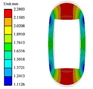
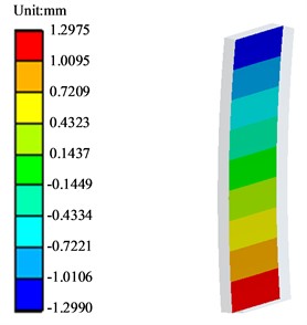
Fig. 5Vertical deformation of HPC y-direction section
At the last time step, the total deformation of the frame as a whole is viewed as shown in Fig. 4, and the vertical deformation of the HPC -directional section is shown in Fig. 5.
From the analysis of Fig. 4, it can be obtained that the overall frame deformation shrinks inward, the result is symmetrical, and the deformation trend is consistent with the actual situation; from the analysis of Fig. 5, it can be obtained that the deformation of the upper and lower ends of the HPC in the middle section in the y direction is basically the same, the deformation direction is opposite, the data is reasonable, and the maximum deformation is 1.2975 + 1.299 = 2.5965 mm. the theoretical calculation value is 2.651 mm, then its error value is:
From the calculation of Eq. (8), the error between the theoretical and simulated values of the final HPC deformation in the vertical direction after winding 7 steps is 2.112 %, which is less than the error allowance of 5 %, and the error is within the acceptable range. Further, the deformation values of the HPC in the vertical middle section in the -direction under seven loading steps were read and compared with the theoretical values to obtain the error of each step after loading with theoretical values is shown in Table 4. In order to make the data analysis more intuitive, a line graph was drawn according to the data is shown in Fig. 6.
Table 4Equivalent pressure loading error analysis
Number of steps | 1 | 2 | 3 | 4 | 5 | 6 | 7 |
Theoretical value (mm) | 0.234 | 0.505 | 0.849 | 1.215 | 1.672 | 2.164 | 2.651 |
Simulation value (mm) | 0.229 | 0.494 | 0.831 | 1.19 | 1.637 | 2.119 | 2.595 |
Error | 2.137 % | 2.178 % | 2.120 % | 2.058 % | 2.093 % | 2.079 % | 2.112 % |
Fig. 6Equivalent pressure loading error analysis
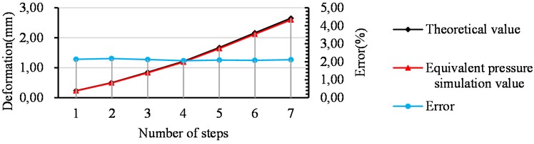
From the analysis of Fig. 6, it can be obtained that the theoretical deformation of the HPC and the simulated deformation through pressure loading are basically the same after each step loading is completed, and the error values are around 2 %, which is very small. Therefore, this simulation calculation method of simulating wire winding by pressure loading is feasible.
4. Equivalent temperature loading on the HPC deformation calculation
Chapter 2 of this article simulates the pre-tensioning effect of the WSW on the frame after winding by directly applying equivalent pressure on the contact surface of the upper and lower semicircular beams and the WSW. Therefore, the WSW structure must be considered when using the finite element method to simulate the working conditions of the hydraulic press to calculate the performance of its structure. The upper and lower semicircular beams of the frame are constrained by the pre-tightening WSW. Therefore, if the WSW structure is ignored, the upper and lower semicircular beams lack constraints that limit their rigid body displacement and cannot be calculated. Therefore, when using the finite element method to simulate the working conditions of the hydraulic press, the WSW structure must be considered to calculate the performance of the hydraulic press structure.
However, it is very difficult to directly simulate the actual wire winding process by FEA methods, so it is necessary to find an equivalent way to simulate wire winding. Based on the fact that most materials have the property of “thermal expansion and contraction”, the pre-tensioning effect of the wire on the frame can be simulated by applying an equivalent low-temperature load to the wire to make the wire shrink, while the rest of the frame structure remains at room temperature, a method called cooling and pressurization. Therefore, this chapter will simulate the pre-tensioning effect of the wire rope on the frame by simulating this equivalent temperature loading method.
4.1. Equivalent temperature calculation
If we want to equivalently model the preload of the wire by equivalent temperature loading, we must know the equivalent temperature applied to the wire. The equation for the relationship between temperature and structural stress is known as [21]:
where, is the equivalent force of the structure, is the modulus of elasticity of the material, is the coefficient of thermal expansion of the material, and is the temperature value.
Then the equivalent temperature value for each step loaded on the wire is calculated as:
where, is the coefficient of thermal expansion of the wire rope material, is the step corresponding to the completion of winding.
The tension applied to the wire rope for each step calculated in Chapter I is substituted into Eq. (10) to obtain the equivalent temperature results applied to each step of the wire as shown in Table 5.
Table 5Equivalent temperature of each step
Number of steps | 1 | 2 | 3 | 4 | 5 | 6 | 7 |
Equivalent temperature value (℃) | –299.202 | –293.452 | –286.12 | –278.297 | –268.509 | –257.926 | –247.475 |
4.2. Deformation calculation of HPC
When the pre-tensioning effect of wire winding on the frame is simulated by equivalent temperature loading, it is a huge nonlinear solution problem because the first layer of wire is linked with the frame by frictional contact, and the wire is also linked with the wire by frictional contact, and 176 wires are laid in each layer, and a total of 79 layers are laid. Therefore, it is unrealistic to simulate the pre-tensioning effect of wire winding exactly according to the actual situation, and some simplification and processing of the solution model are needed.
First, the wire model is simplified, and since the equivalent temperature value loaded on the wire of each step is the same, the wire of each step is simplified to 1 layer of wire, and a total of 7 layers of wire are modeled. Secondly, since the model is symmetric from front to back and left to right, one quarter of the model is taken for the solution calculation and symmetric constraints are applied on the symmetry surface. Finally, the contact surface between the wire and the wire, the contact surface between the wire and the frame, and the contact surface between the upper and lower semicircular beams and the HPC are set as friction contact. Therefore, when setting the friction contact, we need to set the Interface Treatment to Adjust to Touch to make the friction take effect directly to offset the model gap generated by the contraction of the wire rope, and the friction coefficient is set to 0.3.
4.2.1. Solution setting
To simulate the preload effect of wire winding by means of equivalent temperature loading requires solving the temperature field results of the overall model before calculating the structural field results of the frame, so the problem is a thermodynamic coupled dual physical field coupled problem. Since the load loading of the frame is completely symmetric and unconstrained, it is necessary to turn on the weak spring to limit the degrees of freedom of the rigid body when solving the setup. It should be noted that since this paper simulates the wire preload shrinkage by equivalent temperature loading, the temperature field obtained is also an equivalent temperature field, so when loading the equivalent temperature, the equivalent temperature should be applied to all nodes on the frame and the wire, not only on its surface, so that the heat conduction phenomenon occurs between the structure and the structure. Finally, the equivalent temperature corresponding to Table 4 is applied on the steel wire of each step, and the upper and lower semicircular beams of the frame and the steel wire are applied with a room temperature of 22 °C, and then the solution is performed.
4.2.2. View and analysis of results
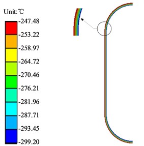
After the solution is completed, the results of the overall temperature field distribution of the frame are shown in Fig.7, and the results of the wire temperature field distribution are shown in Fig. 8. Analysis by Fig. 7 can be intuitively seen, through the equivalent temperature loading, the wire rope produced a contraction effect, and then compress the frame to make it shrink inward, and the deformation results are symmetrical, which shows that this equivalent temperature loading simulation can simulate the contraction effect of the wire rope. In Fig. 8, it can be obtained that the HPC in the y direction of the middle section of the upper and lower ends of the deformation is basically the same, the deformation direction is opposite, the data is reasonable, and the maximum deformation is 1.2756 + 1.2775 = 2.5531 (mm), and the theoretical calculation value is 2.651 (mm), then the error value is:
From the calculation of Eq. (11), the error between the theoretical and simulated values of the final HPC deformation in the vertical direction after winding 7 steps is 3.693 %, which is less than 5 % of the allowable error value, and the error is within the acceptable range.
Fig. 7Overall temperature distribution of frame
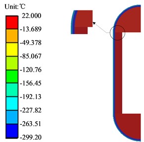
Fig. 8Steel wire temperature distribution chart
Further calculate the deformation value of the HPC in the vertical middle section in the -direction after each step winding is completed, and compare the analysis with the theoretical value to get the error between the theoretical value and the loaded value of each step as shown in Table 6. In order to make the data analysis more intuitive, a line graph is drawn according to the data in Table 6 as shown in Fig. 9.
Table 6Equivalent temperature loading error
Number of steps | 1 | 2 | 3 | 4 | 5 | 6 | 7 |
Theoretical value (mm) | 0.234 | 0.505 | 0.849 | 1.215 | 1.672 | 2.164 | 2.651 |
Simulation value (mm) | 0.245 | 0.527 | 0.876 | 1.239 | 1.689 | 2.127 | 2.553 |
Error | 4.701 % | 4.356 % | 3.180 % | 1.975 % | 1.017 % | 1.710 % | 3.693 % |
Fig. 9Equivalent temperature loading error analysis chart
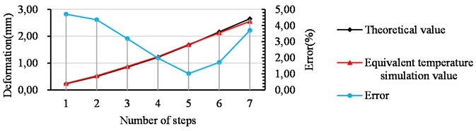
From the analysis of Table 6 and Fig. 9, it can be concluded that the theoretical deformation of the HPC is basically the same as the simulated deformation of the cooling and pressurization loading. Although the error value of each step fluctuates, the allowable error value is less than 5 %, so this simulation calculation method of equivalent temperature loading to simulate wire winding is feasible.
Further analysis shows that the error value tends to decrease first and then increase. In order to see the changes in the error value more clearly and intuitively, it is specially stipulated that when the simulated value is less than the theoretical value, the error value is negative and the error value is positive. This regulation leads to a comparative analysis of the errors of different loading methods calculated by two different simulation methods, pressure loading and equivalent temperature loading, as shown in Fig. 10.
Fig. 10Comparison analysis of the error of the two loading methods
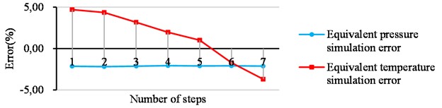
From the analysis of Figs. 4-6, the error value obtained by the equivalent pressure loading is small and consistent. This is because the pressure loading simulation process of different steps only changes the size of the pressure value and does not change other conditions, so the error value but the error value obtained by the equivalent temperature loading method shows a trend of first being positive and then gradually becoming negative. This is because as the number of winding steps increases, the number of wires increases, which in turn leads to an increase in the number of frictional contact pairs between the wires. Therefore, during the pre-tensioning process of the wire, it is also necessary to overcome the tangential friction between the wire and the wire. The more contact, the more work will be done to overcome the friction during the pre-tensioning, resulting in the wire tension is smaller than the theoretical value, so that the error value varies, but the error value is within 5 % of the allowable error value, which does not affect the actual engineering application.
5. Experimental verifications of double frame hydraulic press with PTS using WSW
The feasibility of the two simulation methods has been proved in Chapter 3 and Chapter 4 of this paper. Therefore, the complete model of the frame is established by the 3D software, and the vertical deformation of the vertical center section of the HPC is calculated by the two simulation methods of equivalent pressure loading and equivalent temperature loading, and the resulting cumulative deformation values after winding each step are shown in Table 7.
Table 7HPC deformation calculated by simulation
Number of steps | 1 | 2 | 3 | 4 | 5 | 6 | 7 |
Equivalent pressure simulation value (mm) | 0.231 | 0.502 | 0.847 | 1.211 | 1.670 | 2.161 | 2.652 |
Equivalent temperature simulation value (mm) | 0.241 | 0.512 | 0.855 | 1.212 | 1.662 | 2.133 | 2.573 |
The winding process calculated in Chapter 2 is used to wind the frame. During the wire winding construction, the deformation of the HPC after winding each step is measured and recorded by a surveyor with a high-precision measuring tape as shown in Table 8.
Table 8Actual measured HPC deformation
Number of steps | 1 | 2 | 3 | 4 | 5 | 6 | 7 |
Design length of HPC (mm) | 3880.00 | 3880.00 | 3880.00 | 3880.00 | 3880.00 | 3880.00 | 3880.00 |
Actual length of HPC (mm) | 3879.77 | 3879.49 | 3879.15 | 3878.80 | 3878.35 | 3877.85 | 3877.40 |
Cumulative deformation(mm) | 0.23 | 0.51 | 0.85 | 1.20 | 1.65 | 2.11 | 2.52 |
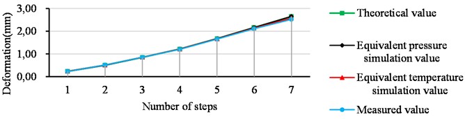
As can be seen from Tables 7 and 8, the line diagram of the cumulative deformation of the HPC in the three cases is shown in Fig. 11. The analysis of Fig. 11 shows that the simulated value and the actual measured value under the two simulation methods fit well, but with the increase of winding layers, the actual measured value is relatively smaller than the simulated value and the theoretical value. This is because in the winding process between the wire rope and the wire rope also to overcome the work of friction, resulting in the relative reduction of the tension of the wire rope, which in turn leads to the deformation of the HPC is small, but such a small difference will not affect the actual engineering applications.
Fig. 11Comparison of cumulative deformation of HPCs
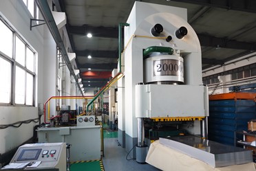
According to the parameters designed in this paper, the site construction drawing of the frame for prestressed steel wire winding is shown in Fig. 12, and the final designed physical drawing of the 20 MN prestressed steel wire winding hydraulic press is shown in Fig. 13. Over the years, users have used it well and the double frames are in good condition. (Remarks: Figs. 12 and 13 are from the cooperation enterprise of the technical team of the corresponding author (China Tianjin Diguang Electromechanical Manufacturing Co., Ltd., the co-author of this article, this model (20 MN double frame press) product is a product supported by the technical team and has been promoted and applied)).
Fig. 12Frame winding site construction drawing
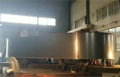
Fig. 13Physical picture of 20 MN double frame press
6. Conclusions
This paper presents a breakthrough in the pre-tightening stress analysis technology of winding steel wires double frames in the field of hydraulic presses. Through the discussion in the previous chapters, the following conclusions can be drawn:
1) Taking a 20 MN double-frame hydraulic press with prestressed steel wire winding is used as the research object. Theoretical calculations show that the deformation of HPC in the vertical direction under the premise of meeting the preload coefficient requirements.
2) In Ansys Workbench software, two different loading methods (equivalent pressure loading and equivalent temperature loading) are used to simulate the pre-tightening effect of the prestressed steel wires on the frame, and the vertical deformation value of the HPC in the vertical center section after each winding step is deduced, and compared with the theoretical value and analyzed the error to elaborate the following conclusions:
– Using the equivalent pressure and temperature loading methods in Ansys, the error between the result and the theoretical value is within 5 %, which meets the error requirements.
– The equivalent pressure loading method only is applied to simulate the preload condition of the hydraulic press, and when simulating the working conditions of the double frames, considering the incomplete constraints, the upper and lower semicircular beams produce small rigid body displacements, which are difficult to solve and calculate accurately, the verification of the effective temperature is demonstrated through field experiments.
– This study further demonstrates that the two simulation methods adopted in this paper are feasible in the actual hydraulic press engineering application and have certain guiding significance for improving the prestressed steel wire winding process.
References
-
Zhu, Y., He, Y., Ren, and J., “Structure analysis and optimization design of the base of four-pillar hydraulic testing press,” in 7th International Conference on Machinery, Material Science and Engineering Application (MMSE), Vol. 2002, p. 01203, 2021, https://doi.org/10.1088/1742-6596/10.1088/1742-6596/2002/1/012036/1/012036/meta
-
L. Li, H. Huang, F. Zhao, M. J. Triebe, and Z. Liu, “Analysis of a novel energy-efficient system with double-actuator for hydraulic press,” Mechatronics, Vol. 47, pp. 77–87, Nov. 2017, https://doi.org/10.1016/j.mechatronics.2017.08.012
-
S. Yin, H. Yang, K. Xu, C. Zhu, and Y. Wang, “Location of abnormal energy consumption and optimization of energy efficiency of hydraulic press considering uncertainty,” Journal of Cleaner Production, Vol. 294, p. 126213, Apr. 2021, https://doi.org/10.1016/j.jclepro.2021.126213
-
J. Wei, Q. Zhang, M. Li, and W. Shi, “High-performance motion control of the hydraulic press based on an extended fuzzy disturbance observer,” Proceedings of the Institution of Mechanical Engineers, Part I: Journal of Systems and Control Engineering, Vol. 230, No. 9, pp. 1044–1061, Oct. 2016, https://doi.org/10.1177/0959651816662562
-
J. Wang and C. Chen, “A Nonlinear vibration compensation method for engineering forging hydraulic press using tabu search algorithm,” Mobile Information Systems, Vol. 2022, pp. 1–10, May 2022, https://doi.org/10.1155/2022/3731211
-
Y. H. Song, Y. N. Yan, and R. J. Zhang, “Finite element analysis of the prestress wire-winding press,” Journal of Materials Processing Technology, Vol. 151, No. 1-3, pp. 255–257, Sep. 2004, https://doi.org/10.1016/j.jmatprotec.2004.04.070
-
R. J. Gu, H. Yang, Y. J. Zhang, Z. Y. Fang, Y. L. Fan, and D. X. Feng, “Study on the pretightening assembly moving beam of open-die forging hydraulic press,” in Advanced Materials Research, Vol. 399-401, pp. 1779–1784, Nov. 2011, https://doi.org/10.4028/www.scientific.net/amr.399-401.1779
-
Y. Lu and J. Zhu, “Stress analysis of pre-stressed steel wire winding ultrahigh pressure vessels based on birth and death element method,” in Advanced Manufacturing and Automation VIII, Vol. 484, pp. 655–662, 2019, https://doi.org/10.1007/978-981-13-2375-1_83
-
R. J. Gu, Y. J. Zhang, Z. Y. Fang, Y. L. Fan, S. F. Zhou, and L. Wu, “Study on the deformation of the prestress frame of open-die forging hydraulic press with different operating modes,” in Advanced Materials Research, Vol. 490-495, pp. 3638–3642, Mar. 2012, https://doi.org/10.4028/www.scientific.net/amr.490-495.3638
-
Su et al., “Pre-stress dynamic performance during filament winding with tension,” Acta Materiae Compositae Sinica, Vol. 36, No. 5, pp. 1143–1150, 2019, https://doi.org/10.13801/j.cnki.fhclxb.20180821.003
-
P. Zhu, L. Zhang, R. Zhou, L. Chen, B. Yu, and Q. Xie, “A novel sensitivity analysis method in structural performance of hydraulic press,” Mathematical Problems in Engineering, Vol. 2012, pp. 1–21, 2012, https://doi.org/10.1155/2012/647127
-
A. Vaishnav, P. Lathiya, and M. Sarvaiya, “Design optimization of hydraulic press plate using finite element analysis,” International Journal of Engineering Research and Applications, Vol. 6, No. 5, pp. 58–66, 2016.
-
W. Zhang, X. Wang, Z. Wang, and S. Yuan, “Structural optimization of cylinder-crown integrated hydraulic press with hemispherical hydraulic cylinder,” Procedia Engineering, Vol. 81, pp. 1663–1668, 2014, https://doi.org/10.1016/j.proeng.2014.10.209
-
K. Raz and K. Vaclav, “Using of a hydraulic press in production and manufacturing of large rings,” Procedia Engineering, Vol. 69, pp. 1064–1069, 2014, https://doi.org/10.1016/j.proeng.2014.03.091
-
Hatapakki, A. B., Gulhane, and U. D., “Design optimization of C frame of hydraulic press machine,” Asian Journal for Convergence in Technology, Vol. 3, No. 2, pp. 1407–1419, 2016.
-
M. Fulland, M. Sander, G. Kullmer, and H. A. Richard, “Analysis of fatigue crack propagation in the frame of a hydraulic press,” Engineering Fracture Mechanics, Vol. 75, No. 3-4, pp. 892–900, Feb. 2008, https://doi.org/10.1016/j.engfracmech.2007.01.006
-
Z. D. Duan and J. J. Wu, “Topological optimization of frame of high speed hydraulic press based on generalized finite element modules,” in Applied Mechanics and Materials, Vol. 44-47, pp. 1828–1832, Dec. 2010, https://doi.org/10.4028/www.scientific.net/amm.44-47.1828
-
H. Li, L. Lang, J. Zhang, and H. Yang, “Cost optimization method of large-scale prestressed wire winded framework on multiple-island genetic algorithm,” Chinese Journal of Aeronautics, Vol. 24, No. 5, pp. 673–680, Oct. 2011, https://doi.org/10.1016/s1000-9361(11)60079-4
-
J. F. Wu, J. B. Lan, K. Hu, and Q. L. Li, “The fatigue life analysis of prestressed wire-wound super-high pressure vessel based on Ansys,” Applied Mechanics and Materials, Vol. 552, pp. 8–14, Jun. 2014, https://doi.org/10.4028/www.scientific.net/amm.552.8
-
D.-M. Yin, B.-M. Li, and H.-C. Xiao, “Analysis for the residual prestress of composite barrel for railgun with tension winding,” Defence Technology, Vol. 16, No. 4, pp. 893–899, Aug. 2020, https://doi.org/10.1016/j.dt.2019.11.008
-
J. Li et al., “Simulation analysis of cylinder winding prestress based on Ansys,” in Journal of Physics: Conference Series, Vol. 2185, No. 1, p. 012006, Jan. 2022, https://doi.org/10.1088/1742-6596/2185/1/012006
About this article

The authors would like to thank the Northeast Forestry University (NEFU), Heilongjiang Institute of Technology (HLJIT), and Huaqiao University for their support. The research topic was supported by the 2022 Heilongjiang Provincial Key Research and Development Plan Key Area Special Project (SC2022ZX01A0052, Xigui Wang, NEFU), the Innovation Foundation for Doctoral Program of Forestry Engineering of Northeast Forestry University (Grant No. 000/4111410203, Jie Tang, NEFU), the Doctoral Research Startup Foundation Project of Heilongjiang Institute of Technology (Grant No. 2020BJ06, Yongmei Wang, HLJIT), the Natural Science Foundation Project of Heilongjiang Province (Grant No. LH2019E114, Baixue Fu, HLJIT), the Basic Scientific Research Business Expenses (Innovation Team Category) Project of Heilongjiang Institute of Engineering (Grant No. 2020CX02, Baixue Fu, HLJIT), the Special Project for Double First-Class-Cultivation of Innovative Talents (Grant No. 000/41113102, Jiafu Ruan, NEFU), the Special Scientific Research Funds for Forest Non-profit Industry (Grant No. 201504508), the Youth Science Fund of Heilongjiang Institute of Technology (Grant No. 2015QJ02), and the Fundamental Research Funds for the Central Universities (Grant No. 2572016CB15).
The datasets generated during and/or analyzed during the current study are available from the corresponding author on reasonable request.
Xigui Wang is mainly responsible for writing manuscript and presided over the organization of the overall work such as the structure of the paper and daily contact. Xinbo Zhang is responsible for the editing of diagrams and reference collection in the manuscript. Zhen Zhang is responsible for the numerical simulation and algorithm analysis of the manuscript. Feng Wang is responsible for the language editing and writing logic of the manuscript. Xiuyan Song assists the members of the research group in the numerical simulation and algorithm analysis of the manuscript.
No conflict of interest exits in the submission of this manuscript, and manuscript is approved by all authors for publication. We would like to declare on behalf of our co-authors that the work described was original research that has not been published previously, and not under consideration for publication elsewhere, in whole or in part. All the authors listed have approved the manuscript that is enclosed.
