Abstract
The mechanical properties of the rope – stiffness and internal friction changes during the movement of cargo. For this reason, under the influence of gravity and inertial forces in the rope having varying tension. Thus, the lift mechanism further exposed to dynamic loads. The highest value of this load is obtained at the beginning of lifting and lowering in place. The mathematical model of the lift mechanism was investigated using the original software package and found dynamic load. In modern control system used cranes lifting mechanism, taking into account the deviation from the vertical rope. Dynamic load on the rope can distort the signals. Results are used to improve the control system of the lifting mechanism.
1. Introduction
Manufacture of large constructions involves some responsible operations, e.g. delivery of separate components to an assembly site. Overhead cranes are used for transport of the same parts. The said cranes just as gantry cranes are used for loading works in ports and railway stations. In order to cut the duration of the said operations, transport speed is increased, thereby adding to momentum in the start and end of transport. This in turn causes additional dynamic loads and poses threat to the service personnel and other objects in the vicinity. While the swing of the payload link poses an interesting control problem a proper representation of the system dynamics is\an essential component in designing an effective controller. The system reduces to an elastic beam with a moving load when the attachment to the payload is removed. One of the earliest studies on beams with moving load was done in monograph [1] is an excellent reference with many analytical solution methods for simple cases. The dynamic response of a beam with intermediate point constraints subjected to a moving load via the method of assumed modes investigated in [2]. The method of assumed modes was also used in [3] to study the dynamic response of a single span beam with a moving load that was caused a uniform partially distributed moving mass. A similar analysis was implemented in [4] with a concentrated moving load. The natural frequencies of vibration of the beam crane system for a stationary crane are investigated in [5] and the explicit frequency equation is derived for that set of cases. Studies related to the dynamics and control of cranes have been mostly based on simplified models of crane structures. A boom crane as a spherical pendulum and a rigid system with two degrees-of-freedom was modeled and assumed that the motion of the platform influences, but is not influenced by the swinging of the payload [6]. The crane structure was also considered as rigid bodies with or without discrete springs in the studies [7-9]. The dynamics of overhead crane system where a beam model was used to represent the flexibility of crane structures was studied [10]. Dynamic response of tower cranes coupled with the pendulum motions of the payload is investigated [11]. The tower crane is modeled by the finite element method, while the pendulum motion is represented as rigid-body kinetics. Integrated governing equations for the coupled dynamics problems are derived based on Lagrange’s equations including the dissipation function. The dynamic loads caused by the crane’s accelerations and decelerations represent an important part of the loadings of the crane’s steel structure [12]. These loads are initiated in all the moving components of the crane, including the payload, and the swinging of the payload is an important cause of the dynamic forces. These loads are initiated in all the moving components of the crane, including the payload, and the swinging of the payload is an important cause of the dynamic forces. The majority of the proposed models are simplified. There was studied the linear motion of the suspension point (typically for overhead travelling cranes) [10], or the curved motion of the suspension point (typically for slewing cranes performing a slewing motion) and therefore with spatial load swinging [13, 14]. In order to achieve more information about dynamics of lifting equipment, a non-linear mathematical model of the load sway during the slewing motion was formulated, and the non-linear nature of the swinging motion for large angles and the non-linearity of the power transmission were considered [15]. The structure’s elasticity and damping, the friction in the main bearing, and the air resistance were also taken into account here.
2. Mathematical model and the program for its computing
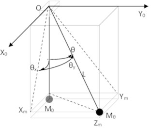
In Fig. 1, a dynamic model of a cargo lifting mechanism using overhead crane is provided. Rope with a hook, where cargo of mass is suspended, is fixed to a rope pulley in point . Rope pulley can move under impact of gear on crane rails on coordinate. Crane with a rope pulley can move under impact of gear on coordinate using support rails. Gears are used to set, by using e.g. controllers, given speed on the axes. The same goes for the length of rope. Diagrams on speeds set during modelling are provided in Fig. 3. We shall assume that the performance mechanisms use high precision in working out given movement, which allows for application of cinematic agitation on , and coordinates. Length of rope L can change under control, force of gravity and dynamic loads.
Fig. 1The dynamic model
The following expressions for kinetic and potential energy and dissipative function were established. Having differentiated Lagrange equations, equations were received for generic , , and coordinates. General solution can be presented as follows:
here: – the length of the rope: , – the length of the rope without a cargo predetermined by a position of the rope drum, – the elongation of the rope caused by a cargo, , – initial relative stiffness of the rope (stiffness of 1 m of the rope), – ratio estimating stiffness increase by rope strain.
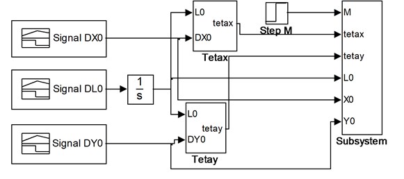
Fig. 2 demonstrates Simulink-diagram of lifting mechanism model based on 1-3 expressions.
Fig. 2Model (Simulink-diagram) of lifting mechanism
3. Terms of simulation
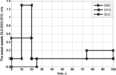
Values of parameters in the model appear in Table 1, while the values of agitation signals appear in Fig. 3. Damping data corresponds to [16].
Table 1The parameters of the model
9.81 | m/s2 | Free fall (gravitational) acceleration | |
10 | m | Initial length of the rope | |
950 | kg | Mass of cargo | |
225 | N·s/m | Damping in the rope | |
1050 | Nm·s/rad | Damping in the cargo suspension point | |
0,28×10⁷ | N | Initial relative tensile stiffness of the rope | |
0,122×108 | N/m | Ratio estimating stiffness increase by rope strain |
Fig. 3Diagrams of change in pre-set speeds of lifting mechanism (DL0), rope pulley (DX0) and crane (DY0)
4. The results of the investigation and discussion
Processing of modelling results employs the following correlations between key and auxiliary coordinates:
1. Projections of distances from suspension point on rope pulley to cargo centre of gravity:
2. Distance from starting point of movement to cargo centre of gravity and height of hook over ground level:
where – starting height of hook position, – current height of hook.
Fig. 4 provides trajectories of key coordinates in the model based on modelling session.
Fig. 4Changes in angles of swinging θx, θy in cycle of movement of cargo
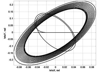
As demonstrated in Fig. 4 in case of horizontal movement of cargo suspended on hook, swing occurs.
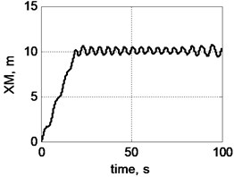
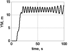
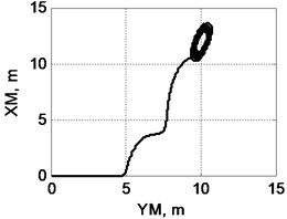
Fig. 5 demonstrates change in location of centre of cargo gravity in movement cycle.
Fig. 5Trajectory of cargo movement given operation of lifting mechanism and taking into account swinging: a) on XM coordinate; b) on YM coordinate; c) view of trajectory from above; d) view of trajectory in space: 1 – actual trajectory taking into account cargo swinging, 2 – trajectory set by movement of crane mechanisms
a)
b)
c)
d)
Fig. 5 demonstrates that swinging can materially distort trajectory of movement of cargo, which in turn can have severe consequences. Amplitude of swinging changes in course of movement of freight and depends, e.g. on scope and nature of horizontal acceleration at cargo suspension point, length of rope and other factors.
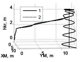
Fig. 6 displays nature of cargo swinging at the end of movement cycle, when engines of horizontal movement are switched off, and the winch of rope pulley brings down the cargo.
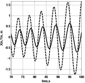
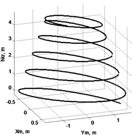
Fig. 6Nature of swinging of cargo, when winch of rope pulley operates on lowering only: a) components Xm (solid line) and Ym (dotted line), b) view of trajectory in space
a)
b)
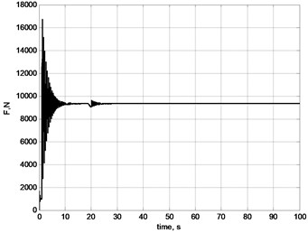
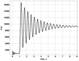
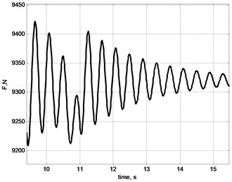
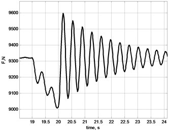
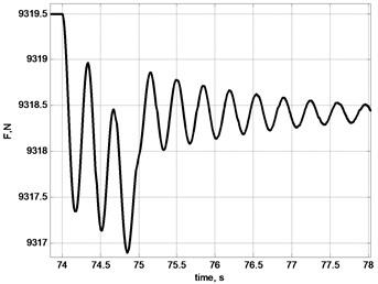
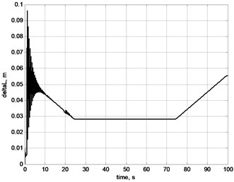
Fig. 7Oscillations of stretching effort on rope: a) general picture; b) by selection of ease of rope; c) by acceleration of gear of X axis; d) by breaking of gears in X and Y axes; e) by acceleration of lifting mechanism; f) linear stretch of rope δL
a)
b)
c)
d)
e)
f)
Notably the amplitude of swinging in case of lowering cargo (Fig. 6) increases. In the meantime however one must stabilise position of cargo before placing the same on the foundation. In order to stabilise the position one must weight for a certain time or take special means to tackle swinging. Amplitude of swinging can be reduced by making use of special laws [17] of smooth acceleration and breaking of horizontal movement as well as by applying other laws on optimum movement, e.g. by using soft logic [18] and return correlation on deviation of cargo rope from vertical position.
Fig. 7 demonstrates results of modelling of longitudinal load of rope in the cycle of movement of cargo. Different events, e.g. sudden selection of ease, turning on and off controllers of horizontal movement, swinging of cargo; all cause change in longitudinal force, which affects the rope and frequencies of oscillations [19, 20].
Fig. 8 demonstrates changes in frequency of proper oscillations of cargo suspended on an elastic rope as operational length of rope changes. This can be explained by the fact that longitudinal stiffness of rope (for stretching) decreases as the length increases. The model has demonstrated increase in frequency at 1.38 times while the length of rope was reduced by 1.9 times.
Fig. 8Dependence of frequency of cargo oscillations when suspended on a rope from operational length of the rope
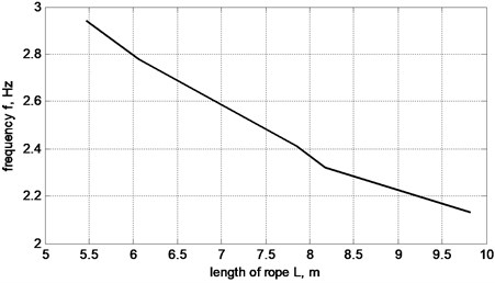
Fig. 9Rope stiffness dependence k from rope elongation δL
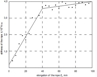
Preparing data for modelling the investigation of rope strain was performed. The results of the investigation are presented in Fig. 9. The increase of rope strain is estimated by rate .
As a result of modelling session trajectories of key coordinates were obtained in cycle of movement of cargo. Analysis of dependences obtained allows for stating that inertia forces in the start and end of transportation make delivery of cargo more difficult given strict requirements on precision positioning. This must be taken into account when designing mechatronic control software.
5. Conclusions
1) In the beginning of the lifting process, additional dynamic loads appear. The value of the dynamic load factor achieves up to 1.7. The duration of the impact – up to 10 s.
2) On cargo swinging, dynamic loads appear in the rope. The value of the dynamic load factor depends on the amplitude of swinging. On appearance of swinging, the frequency of the dynamic loads is not bound with the frequency of swinging, but depends on the stiffness of the rope and mass of the cargo. Later, the frequency of the dynamic loads becomes equal to the frequency of swinging and they act within the whole period of swinging.
3) The dynamic load of the rope in begging of swinging is significantly bigger in comparison with ones during further transportation.
4) On cargo descending, the amplitude of cargo swinging increases: the precision of cargo delivery decrease as well.
5) The amplitude of the swing depends on the nature and horizontal accelerations of the suspension point, load rope length and other factors. The amplitude of the swing can be reduced by smooth acceleration and deceleration of horizontal displacement. The swing can be significantly reduced by reversing the gear of displacement at the end of transportation. The most effect can be get using combination equal acceleration and deceleration.
References
-
Fryba L. Vibration of Solids and Structures under Moving Loads. Groningen, Nordhoff, 1972.
-
Lee H. P. Dynamic response of a beam with intermediate point constraints subject to a moving load. Journal of Sound and Vibration, Vol. 171, 1976, p. 369-395.
-
Esmailzadeh E., Ghorshi M. Vibration analysis of beams traversed by uniform partially distributed moving masses. Journal of Sound and Vibration, Vol. 184, 1995, p. 9-17.
-
Michaltsos G., Sophoanopoulos D., Kouadis A. N. The effect of a moving mass and other parameters on the dynamic response of a simply supported beam. Journal of Sound and Vibration, Vol. 191, 1996, p. 357-362.
-
Oguamanam D. C. D., Hansen J. S. Dynamic response of an overhead crane system. Journal of Sound and Vibration, Vol. 213, Issue 5, 1998, p. 889-906.
-
Chin C., Nayfeh A. H., Abdel-Rahman E. Nonlinear dynamics on a boom crane. Journal of Vibration and Control, Vol. 7, Issue 2, 2001, p. 199-220.
-
Towarek Z. Dynamic stability of crane standing on soil during the rotation of the boom. International Journal of Mechanical Science, Vol. 40, Issue 6, 1998, p. 557-574.
-
Kiliceaslan S., Balkan T., Ider S. K. Tipping loads of mobile cranes with flexible booms. Journal of Sound and Vibration, Vol. 223, Issue 4, 1999, p. 645-657.
-
Ghigliazza R. M., Holmes P. On the dynamics of cranes, or spherical pendula with moving supports. International Journal of Non-Linear Mechanics, Vol. 37, Issue 6, 2002, p. 1211-1221.
-
Oguamanam D. C. D., Hansen J. S., Heppler G. R. Dynamics of a three-dimensional overhead crane system. Journal of Sound and Vibration, Vol. 242, Issue 3, 2001, p. 411-426.
-
Ju F., Choo Y. S., Cui F. S. Dynamic response of tower crane induced by the pendulum motion of the payload. International Journal of Solids and Structures, Vol. 43, 2006, p. 376-389.
-
Abdel-Rahman E. M., Nayfeh A. H., Masoud Z. N. Dynamics and control of cranes: a review. Journal of Vibration and Control, Vol. 9, 2003, p. 863-908.
-
Ghigliazza R. M., Holmes P. On the dynamics of cranes, or spherical pendula with moving supports. International Journal of Non-Linear Mechanics, Vol. 37, 2002, p. 1211-1221.
-
Spathopoulos M. P., Fragopoulos D. Pendulation control of an offshore crane. International Journal of Control, Vol. 77, Issue 7, 2004, p. 654-670.
-
Jerman B., Podržaj P., Kramar J. An investigation of slewing-crane dynamics during slewing motion development and verification of a mathematical model. International Journal of Mechanical Sciences, Vol. 46, 2004, p. 729-750.
-
Lobov N. A. Dynamic of Hoisting Kranes. Maschinostrojenije, Moscow, 1987, (in Russian).
-
Slivinskas K., Gičan V., Striška V., Poška A. J. Optimization of the transport movement parameters of the transfer manipulator for the quenching bath according to technological process requirements. The 5th International Conference of Mechatronic Systems and Materials, Vilnius, 2009, p. 110.
-
Sung-Kun Cho, Ho-Hoon Lee A fuzzy-logic antiswing controller for three-dimensional overhead cranes. ISA Transactions, Vol. 41, 2002, p. 235-243.
-
Spruogis B., Jakštas A., Turla V., Iljin I., Šešok N. Dynamic reaction forces of an overhead crane on lifting. Transport, Vol. 26, Issue 3, 2011, p. 279-283.
-
Jianqiang Y., Naoyoshi Y., Kaoru H. Anti-swing and positioning control of overhead traveling crane. Information Sciences, Vol. 155, 2003, p. 19-42.
About this article

